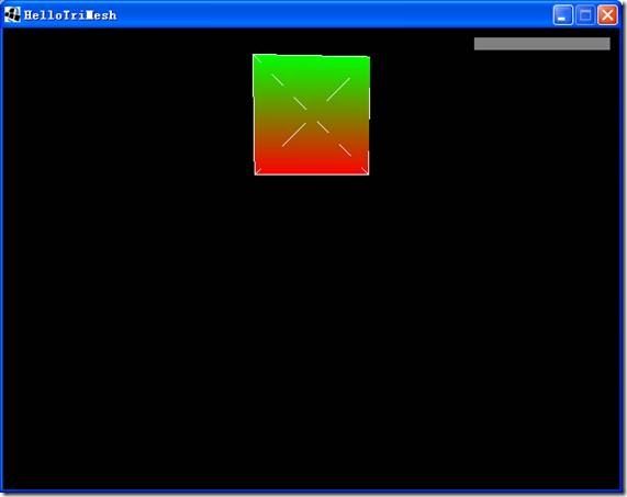
6、示例3:Hello TriMesh
// TriMesh is what most of what is drawn in jME actually is
TriMesh m=new TriMesh("My Mesh");
TriMesh类是jME中最最常用的类。可以看看Box和Sphere的源代码:
public class Box extends AbstractBox
public abstract class AbstractBox extends TriMesh implements Savable
public class Sphere extends TriMesh
可见Box和Sphere都是从TriMesh派生出来的。
注意:不要使用TriMesh的默认构造函数,即new TriMesh(),而要使用new TriMesh(“String name”)构造。因为默认构造函数仅仅作为内部使用。其他的也是一样,比如Node, Box, Sphere, 及其他从 com.jme.scene.Spatial派生出来类。TriMesh也是从Spatial派生出来的:
public class TriMesh extends Geometry implements Serializable
public abstract class Geometry extends Spatial implements Serializable, Savable
// Vertex positions for the mesh
Vector3f[] vertexes={
new Vector3f(0,0,0),
new Vector3f(1,0,0),
new Vector3f(0,1,0),
new Vector3f(1,1,0)
};
这定义了三角形的顶点坐标。要用三角形来构造一个矩形。
// Normal directions for each vertex position
Vector3f[] normals={
new Vector3f(0,0,1),
new Vector3f(0,0,1),
new Vector3f(0,0,1),
new Vector3f(0,0,1)
};
定义了法线(Normal是法线的意思),每个顶点的法线方向。Normals和vertexes是一一对应的:即vertexes[i]的法线是normals[i]。法线是三维图形里面最常见的概念。
每个顶点都有一个颜色:
// Color for each vertex position
ColorRGBA[] colors={
new ColorRGBA(1,0,0,1), //红色
new ColorRGBA(1,0,0,1), //红色
new ColorRGBA(0,1,0,1), //绿色
new ColorRGBA(0,1,0,1) //绿色
};
你会发现前两个顶点的位置:vertexes[0]=(0,0,0) 和 vertexes[1]=(1,0,0) 是矩形的底边,后两个:vertexes[2]=(0,1,0) 和 vertexes[3]=(1,1,0) 是矩形的顶边。看看开头的预览图,矩形从下到上由红色平滑过渡到绿色了。
下面定义纹理坐标(Texture Coordinates):
// Texture Coordinates for each position
Vector2f[] texCoords={
new Vector2f(0,0),
new Vector2f(1,0),
new Vector2f(0,1),
new Vector2f(1,1)
};
随着对3D图形的深入我们会对texture coordinates逐渐清晰起来。Vector2f和Vector3f基本一样,Vector2f是二维向量,由两个float值构造。
最后需要为My Mesh指定索引:
// The indexes of Vertex/Normal/Color/TexCoord sets. Every 3 makes a triangle.
int[] indexes={
0,1,2,1,2,3
};
TriMesh 就是Triangle mesh.(三角网格),是三角形的集合。索引数组的长度必须是3的倍数,因为三角形总是有三个顶点。上面的数组长度为6,说明有两个三角形组成。前三个为{0,1,2},意思是m对象的第一个三角形通过连线vertexes [0] → vertexes [1] → vertexes [2]画成的。Vertex [0] 的法线是normals [0], 颜色是colors [0], texture coordinate 是texCoords [0]。第二个三角形是vertexes [1] → vertexes [2] → vertexes [3]。注意下面的定义式非法的:
int[] indexes={
0,1,2,1,2,4
};
因为没有vertexes[4]。
然后我们把它组合起来:
// Feed the information to the TriMesh
m.reconstruct(BufferUtils.createFloatBuffer(vertexes), BufferUtils.createFloatBuffer(normals),
BufferUtils.createFloatBuffer(colors), TexCoords.makeNew(texCoords), BufferUtils.createIntBuffer(indexes));
这个例子中实际并没有使用到texCoords,在使用图片的时候它才有效果。下面这样写跟他是等价的:
m.reconstruct(BufferUtils.createFloatBuffer(vertexes), BufferUtils.createFloatBuffer(normals),
BufferUtils.createFloatBuffer(colors), null, BufferUtils.createIntBuffer(indexes));
甚至这样都行:
m.reconstruct(BufferUtils.createFloatBuffer(vertexes), null,
null, null, BufferUtils.createIntBuffer(indexes));
这样就是个灰色的TriMesh。
最后,为它附着一个边界:
// Create a bounds
m.setModelBound(new BoundingBox());
m.updateModelBound();
// Attach the mesh to my scene graph
rootNode.attachChild(m);
// Let us see the per vertex colors
lightState.setEnabled(false);
加上最后一行代码lightState.setEnabled(false)使我们能看到彩虹效果的方盒。
按“B”看看边界线:
我们去掉最后一行代码,看看效果:
看到了吗,是两个三角形。
下面是本例的场景图:
| rootNode |
| “My Mesh” |

