Multicast1
为什么要使用多播呢?
1、多播有组的概念,也就是一组需要改数据的人
2、送数据到多个接收点
3、减少CPU和带宽的占用
4、不知道接收地址的时候
5、数据需要的实时性和同时性
6、随着接收点增多,带宽不会随着增长,很稳定
缺点:
1、多播是基于UDP的
2、尽力传输
3、无拥塞避免机制
4、无序
5、有时会造成重复包
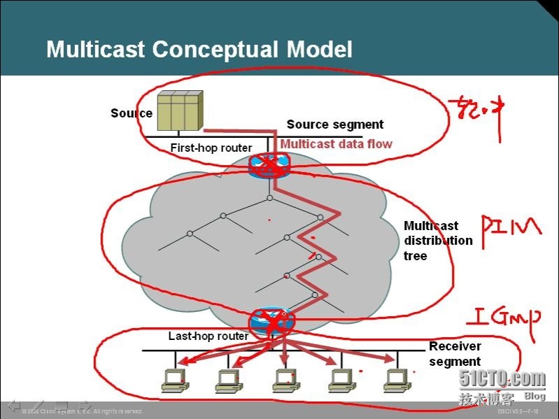
多播的模型:
1、first-hop
2、last-hop

主机到路由器之间是IGMP
路由器和路由器之间有 域内多播PIM 域外是MBGP/MSDP
多播地址范围:224.0.0.0-239.255.255.255 有28bit的groupID
多播地址不能配置在接口上,不能当做源地址,只能当做目的地址
1、保留地址 224.0.0.0/24
224.0.0.1 所有主机和路由器
224.0.0.2 所有的路由器
224.0.0.5 OSPF
224.0.0.6 OSPF
224.0.0.9 RIP V2
224.0.0.10 EIGRP
224.0.0.13 PIM
2、全局地址2224.0.1.0-238.255.255.255
指定源的多播:232.0.0.0 to 232.255.255.255
GLOP地址:233.0.0.0/8
你申请一个AS号就送一段GLOP地址
AS65123:将65123化成16进程数:OXFE63
0XFE=254
0X63=99
233.254.99.0/24,这就是GLOP地址
3、私有地址239.0.0.0/8
IGMP:Internet Group Management Protocol
V1:有两种报文,一个查询,一个report包
路由器发查询包(60秒发一次,224.0.0.1),主机回复report包
ver+type+unused+校验和+group address
report报文,目的IP为:组播IP G:组播IP
让路由器和其他组员知道,
好处:
1、让路由器和本组组员知道
2、抑制其他组员的report报文
3、主动告知新组员的加入
IGMPv1的leaving 消息
IGMP v2:
有四种报文:
1、新增报文 指定组查询
2、离组报文
查询者的概念:
当有两台发送查询报文的路由器的话,所以需要选举查询者
是通过查询包选出来,比IP地址最小的获选
IGMP v1 可以通过PIM 选举DR来选举查询者
备份查询者判断查询者在120秒内没响应,替换查询者
IGMP v2报文格式
type+ 最大响应时间+校验和+group address
show ip igmp inteface e0
离组消息:
离组主机发出离组报文
目标地址:224.0.0.2
组地址:组播IP
路由器发送指定组的查询,若无其他组员回复,在几秒内删除路由器上的组播组
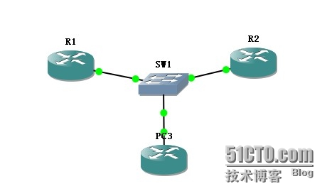
现在来一个小实验随便验证下

一、预配
R1:
interface f0/0
ip address 123.1.1.1 255.255.255.0
no shut
R2:
interface f0/0
ip address 123.1.1.2 255.255.255.0
no shut
PC3:
interface f0/0
ip address 123.1.1.3 255.255.255.0
no shut
二、运行多播协议PIM
R1:
ip multicast-routing
interface f0/0
ip pim sparse-mode
R2:
ip multicast-routing
interface f0/0
ip pim sparse-mode
PC3:
interface f0/0
ip igmp join-group 224.1.1.1
因为有两个路由器,那么谁是查询者呢?
在R2上show ip igmp interface f0/0
R2(config-if)#do show ip igmp interface f0/0
FastEthernet0/0 is up, line protocol is up
Internet address is 123.1.1.2/24
IGMP is enabled on interface
Current IGMP host version is 2
Current IGMP router version is 2
IGMP query interval is 60 seconds
IGMP querier timeout is 120 seconds
IGMP max query response time is 10 seconds
Last member query count is 2
Last member query response interval is 1000 ms
Inbound IGMP access group is not set
IGMP activity: 2 joins, 0 leaves
Multicast routing is enabled on interface
Multicast TTL threshold is 0
Multicast designated router (DR) is 123.1.1.2 (this system)
IGMP querying router is 123.1.1.1
Multicast groups joined by this system (number of users):
224.0.1.40(1)
R2#show ip igmp groups
IGMP Connected Group Membership
Group Address Interface Uptime Expires Last Reporter Group Accounted
224.1.1.1 FastEthernet0/0 00:10:55 00:02:15 123.1.1.3
224.0.1.40 FastEthernet0/0 00:10:56 00:02:08 123.1.1.1
R1#show ip igmp groups
IGMP Connected Group Membership
Group Address Interface Uptime Expires Last Reporter Group Accounted
224.1.1.1 FastEthernet0/0 00:12:08 00:02:13 123.1.1.3
224.0.1.40 FastEthernet0/0 00:12:09 00:02:13 123.1.1.2
通过show ip igmp groups可以查看组员信息,这里224.1.1.1的组员就是123.1.1.3
而红色部分,组播地址是224.0.1.40的report路由器是不同的
所以应该是彼此发送用来选举DR的
设计让主机发送离组信息
interface f0/0
no ip dimp join-group 224.1.1.1
并在设备上开启debug ip igmp
可以查看到如下信息:
Mar 1 00:32:24.607: IGMP(0): Received Leave from 123.1.1.3 (FastEthernet0/0) for 224.1.1.1
*Mar 1 00:32:24.607: IGMP(0): Received Group record for group 224.1.1.1, mode 3 from 123.1.1.3 for 0 sources
*Mar 1 00:32:24.611: IGMP(0): Lower expiration timer to 2000 msec for 224.1.1.1 on FastEthernet0/0
*Mar 1 00:32:24.611: IGMP(0): Send v2 Query on FastEthernet0/0 for group 224.1.1.1
主机离组后的过程就是这样,路由器接收到此包后,降低抑制时间为2秒并发送指定组的查询报文
在2秒内没有收到report,删除本地设备上的该组播地址的信息
R1#show ip igmp groups
IGMP Connected Group Membership
Group Address Interface Uptime Expires Last Reporter Group Accounted
224.0.1.40 FastEthernet0/0 00:25:10 00:02:16 123.1.1.2
R2#show ip igmp groups
IGMP Connected Group Membership
Group Address Interface Uptime Expires Last Reporter Group Accounted
224.0.1.40 FastEthernet0/0 00:25:47 00:02:16 123.1.1.2
二层组播地址:IP地址对应的组播二层地址
IP Snooping 只要在交换机上做就可以了
截获report多播包,拆包到三层,形成表项

演示ip igmp snooping
R1:
interface f0/0
ip address 13.1.1.1 255.255.255.0
no shut
ip pim sparse-mode
ip multicast-routing
Sw1:
ip igmp snooping vlan 1
R3:
interface f0/0
ip address 13.1.1.3 255.255.255.0
no shut
ip igmp join-group 224.1.1.1
在Sw1上show ip igmp snooping groups
建议用硬件模块去专门处理IGMP snooping报文
CGMP要在交换机和路由器一起做。
是思科私有的,CGMP载荷里有GDA和USA字段,GDA组播目的MAC地址 USA单播源MAC地址
这里的交换机就不需要拆包了,是路由器去拆包了。
交换机上全局下cgmp就可以了,而在路由器上,在接口下ip cgmp就可以了
多播转发:
多播路由关心的是包怎么进来,而单播是关心包怎么出去
RPF反向路径转发,一台路由器只有一个RPF接口
RPF校验,解决重复包问题
查看包的源IP地址在本地路由表中,看入接口和出接口是否是同一个,如果不是校验不合格
校验合格的话,包向需要的接口转发
选RPF接口原则:
1、先比较小的AD值
2、小的metric
3、较大的IP地址
基于组来负载分担,可以用多播静态路由,仅用来选RPF接口,不用于多播包的转发
ip mroute 源IP地址 掩码 RPF接口
show ip mroute static 静态路由AD为0
树形结构:
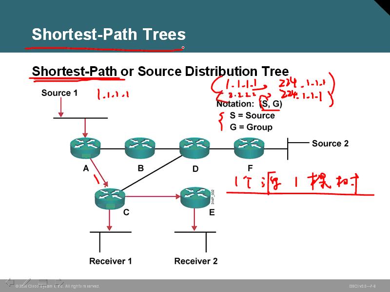
1、源树 SPT
一个源就是一个树
会产生一个多播表
 好处:源到目的路径最短
坏处:一个树很耗费内存啊 就是应用于dense模式
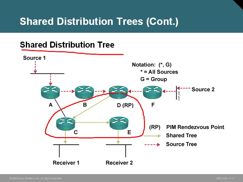
2、共享树 RPT
先找点一个RP结合点,两个源的流量先到一个结合点,然后下方到接收端

这是典型的sparse模式
PIM两种模式:
sparse mode
dense mode
dense模式是应用于接受者很多的情况下,用push
使用SPT树模型,初始泛洪,不管有没有接受者,都声称源树
下面没有接受者的,会发送pruning包,就没有多播流量发过来了
FLOOD和PRUNE每3分钟一次
PIM的工作过程:
如果你运行的IGMPV1 DR就是查询者
1、建立邻居
2、发hello包 组播地址224.0.0.13 每30秒一次,holdtime3.5倍
PIM直接封装在IP包中,协议字段号103
DR:高优先级和高IP地址,选举规则就是如此。
show ip pim neighbor
模式:
S 表示状态可以刷新
B 表示双向PIM
N 表示有低端设备没有标示DR优先级

这是dense mode的演示实验
1、预配
R1:
interface s1/0
ip address 12.1.1.1 255.255.255.0
no shut
interface s1/1
ip address 13.1.1.1 255.255.255.0
no shut
interface f0/0
ip address 16.1.1.1 255.255.255.0
no shut
interface l0
ip address 1.1.1.1 255.255.255.0
no shut
R2:
interface s1/0
ip address 12.1.1.2 255.255.255.0
no shut
interface s1/1
ip address 24.1.1.2 255.255.255.0
no shut
interface lo0
ip address 2.2.2.2 255.255.255.0
no shut
R3:
interface s1/1
ip address 13.1.1.3 255.255.255.0
no shut
interface s1/0
ip address 35.1.1.3 255.255.255.0
no shut
interface lo0
ip address 3.3.3.3 255.255.255.0
no shut
R4:
interface s1/1
ip address 24.1.1.4 255.255.255.0
no shut
interface lo0
ip address 4.4.4.4 255.255.255.0
no shut
R5:
interface s1/0
ip address 35.1.1.5 255.255.255.0
no shut
interface lo0
ip address 5.5.5.5 255.255.255.0
no shut
R6:
interface f0/0
ip address 16.1.1.6 255.255.255.0
no shut
interface lo0
ip address 6.6.6.6 255.255.255.0
no shut
no ip routing
ip default-gateway 35.1.1.3
2、在中间路由器上配置IGP,实现路由可达
R1:
router ospf 110
router-id 1.1.1.1
network 12.1.1.0 0.0.0.255 area 0
network 13.1.1.0 0.0.0.255 area 0
network 16.1.1.0 0.0.0.255 area 0
R2:
router ospf 110
router-id 2.2.2.2
network 12.1.1.0 0.0.0.255 area 0
R3:
router ospf 110
router-id 3.3.3.3
network 13.1.1.0 0.0.0.255 area 0
R6:
router ospf 110
router-id 6.6.6.6
network 16.1.1.0 0.0.0.255 area 0
3、配置PIM协议,启用dense mode
R2:
ip multicast-routing
interface s1/0
ip pim dense-mode
interface s1/1
ip pim dense-mode
R1:
ip multicast-routing
interface s1/0
ip pim dense-mode
interface s1/1
ip pim dense-mode
interface f0/0
ip pim dense-mode
R3:
ip multicast-routing
interface s1/0
ip pim dense-mode
interface s1/1
ip pim dense-mode
R6:
ip multicast-routing
interface f0/0
ip pim dense-mode
R5:
interface s1/0
ip igmp join-group 224.1.1.1
至此,关于dense mode 的配置结束
以下是几个验证命令:
1、show ip pim neighbor 用来查看PIM建立的邻居表
PIM Neighbor Table
Mode: B - Bidir Capable, DR - Designated Router, N - Default DR Priority,
S - State Refresh Capable
Neighbor Interface Uptime/Expires Ver DR
Address Prio/Mode
12.1.1.2 Serial1/0 00:31:01/00:01:43 v2 1 / S
13.1.1.3 Serial1/1 00:30:12/00:01:36 v2 1 / S
16.1.1.6 FastEthernet0/0 00:00:25/00:01:19 v2 1 / DR S
2、show ip pim interface 查看有运行PIM的接口
Address Interface Ver/ Nbr Query DR DR
Mode Count Intvl Prior
12.1.1.1 Serial1/0 v2/D 1 30 1 0.0.0.0
13.1.1.1 Serial1/1 v2/D 1 30 1 0.0.0.0
16.1.1.1 FastEthernet0/0 v2/D 1 30 1 16.1.1.6
3、show ip mroute 查看多播路由表
IP Multicast Routing Table
Flags: D - Dense, S - Sparse, B - Bidir Group, s - SSM Group, C - Connected,
L - Local, P - Pruned, R - RP-bit set, F - Register flag,
T - SPT-bit set, J - Join SPT, M - MSDP created entry,
X - Proxy Join Timer Running, A - Candidate for MSDP Advertisement,
U - URD, I - Received Source Specific Host Report,
Z - Multicast Tunnel, z - MDT-data group sender,
Y - Joined MDT-data group, y - Sending to MDT-data group
Outgoing interface flags: H - Hardware switched, A - Assert winner
Timers: Uptime/Expires
Interface state: Interface, Next-Hop or VCD, State/Mode
(*, 224.1.1.1), 00:31:31/stopped, RP 0.0.0.0, flags: D
Incoming interface: Null, RPF nbr 0.0.0.0
Outgoing interface list:
FastEthernet0/0, Forward/Dense, 00:03:23/00:00:00
Serial1/1, Forward/Dense, 00:31:31/00:00:00
Serial1/0, Forward/Dense, 00:31:31/00:00:00
(24.1.1.4, 224.1.1.1), 00:31:31/00:02:51, flags: T
Incoming interface: Serial1/0, RPF nbr 12.1.1.2
Outgoing interface list:
FastEthernet0/0, Prune/Dense, 00:00:22/00:02:37
Serial1/1, Forward/Dense, 00:31:32/00:00:00
(*, 224.0.1.40), 00:34:00/00:02:21, RP 0.0.0.0, flags: DCL
Incoming interface: Null, RPF nbr 0.0.0.0
Outgoing interface list:
FastEthernet0/0, Forward/Dense, 00:03:24/00:00:00
Serial1/1, Forward/Dense, 00:33:11/00:00:00
Serial1/0, Forward/Dense, 00:34:00/00:00:00
红色部分比较主要,(24.1.1.4,224.1.1.1) flags T 这里的T就是SPT置位,说明该条目可以转发
多播流量,源是24.1.1.4 目的多播地址是224.1.1.1
incoming interface:s1/0 就是RP接口,它的邻居接口IP是12.1.1.2
outgoing interface list:就是出去的接口列表
f0/0 prune/dense 说明该接口接收到pruning报文,被修剪了,不能用于转发多播流量
s1/1 forward/dense 可以用于转发 00:31:32/00:00:00说明随时可以发送,因为没有收到
pruning报文,所以时间不需要被重置,00代表可以随时发
dense mode 是push流量
想断掉ping程序,Ctrl+shift+6
sparse mode:是使用pull流量
pull包是由接受者发送的,发给RP的,包是这样的
(*,G)join包,这样shared tree就形成了
源首先向RP发送单播register报文
(S,G)register PIM的载荷是多播信息,外层封装的是单播报文
它发送这个报文,问RP有没有接收者(是否有该组的组员)
是的话,就拆包,将里面的多播包发送给接收者
RP这时候会发校验信息(S,G)join包,形成完整的SPT
由于整个SPT是由RP形成的,可能并不是最优的,可以自动切换
它有个缺省值,默认是0kbps,超过就会切换
RP的作用就是告诉源,接收者在哪里,然后计算最短路径
RP的指定:
1、静态
2、auto-RP 思科私有
3、BSR
1、静态RP的指定
命令:全局模式下,ip pim rp-address ip地址
该IP地址最好选择环回口,该接口稳定
在该拓扑中,将R1作为RP,而该环回口IP需要路由可达,必须先宣告进IGP
R1:
router ospf 110
network 1.1.1.0 0.0.0.255 area 0
R2:ip pim rp-address 1.1.1.1
R3: ip pim rp-address 1.1.1.1
R6:ip pim rp-address 1.1.1.1
呵呵,我们好像还忘了件事情,那就是R1路由器本身也是需要知道它自己就是这个“大班长”RP
R1:ip pim rp-address 1.1.1.1
R4源没有发送多播流量的前提下,在RP和接收者之间会形成共享树RPT吗?
因为之前我们Ping过了,为了验证这个结论,我们需要在相关的路由器上clear ip mroute *
之后我们再来查看下RP,也就是R1上有我们想看到的东西不?
(*,G)join是否有没有发送,我们在R5上debug ip igmp
呵呵,我们好像搞错一个问题哦!那就是(*,G)join包不是有R5发的(因为R5用来模拟PC了哦)
是离R5最近的R3来发的哦,为了看到该包,我们不能debup ip igmp
而是debug ip pim,以下就是我看到消息,复制给大家看下
*Mar 1 02:07:57.739: PIM(0): Building Periodic (*,G) Join / (S,G,RP-bit) Prune message for 224.1.1.1
*Mar 1 02:07:57.739: PIM(0): Insert (*,224.1.1.1) join in nbr 13.1.1.1's queue
*Mar 1 02:07:57.743: PIM(0): Building Join/Prune packet for nbr 13.1.1.1
*Mar 1 02:07:57.743: PIM(0): Adding v2 (1.1.1.1/32, 224.1.1.1), WC-bit, RPT-bit, S-bit Join
*Mar 1 02:07:57.747: PIM(0): Send v2 join/prune to 13.1.1.1 (Serial1/1)
R3#show ip mroute
IP Multicast Routing Table
Flags: D - Dense, S - Sparse, B - Bidir Group, s - SSM Group, C - Connected,
L - Local, P - Pruned, R - RP-bit set, F - Register flag,
T - SPT-bit set, J - Join SPT, M - MSDP created entry,
X - Proxy Join Timer Running, A - Candidate for MSDP Advertisement,
U - URD, I - Received Source Specific Host Report,
Z - Multicast Tunnel, z - MDT-data group sender,
Y - Joined MDT-data group, y - Sending to MDT-data group
Outgoing interface flags: H - Hardware switched, A - Assert winner
Timers: Uptime/Expires
Interface state: Interface, Next-Hop or VCD, State/Mode
(*, 224.1.1.1), 00:08:50/00:02:11, RP 1.1.1.1, flags: SC
Incoming interface: Serial1/1, RPF nbr 13.1.1.1
Outgoing interface list:
Serial1/0, Forward/Sparse, 00:08:50/00:02:11
(*, 224.0.1.40), 00:09:20/stopped, RP 1.1.1.1, flags: SPCL
Incoming interface: Serial1/1, RPF nbr 13.1.1.1
Outgoing interface list: Null
这个模拟环境的大前提是我们要在R3上关闭RP的自动切换,而且必须是R3
命令是 ip pim spt-threshold infinity 源树从不切换,这样我们才可以看到共享树
现在我们开启切换,看有有什么不同
上面那条命令no掉就可以了,还有哦,我还忘了一件事,那就是在R4上不ping就可以了啊
不需要前面的大前提了哦!
R1#show ip mroute
IP Multicast Routing Table
Flags: D - Dense, S - Sparse, B - Bidir Group, s - SSM Group, C - Connected,
L - Local, P - Pruned, R - RP-bit set, F - Register flag,
T - SPT-bit set, J - Join SPT, M - MSDP created entry,
X - Proxy Join Timer Running, A - Candidate for MSDP Advertisement,
U - URD, I - Received Source Specific Host Report,
Z - Multicast Tunnel, z - MDT-data group sender,
Y - Joined MDT-data group, y - Sending to MDT-data group
Outgoing interface flags: H - Hardware switched, A - Assert winner
Timers: Uptime/Expires
Interface state: Interface, Next-Hop or VCD, State/Mode
(*, 224.1.1.1), 00:02:43/stopped, RP 1.1.1.1, flags: S
Incoming interface: Null, RPF nbr 0.0.0.0
Outgoing interface list:
Serial1/1, Forward/Sparse, 00:02:43/00:02:43
(24.1.1.4, 224.1.1.1), 00:00:16/00:02:43, flags:
Incoming interface: Serial1/0, RPF nbr 12.1.1.2
Outgoing interface list:
Serial1/1, Forward/Sparse, 00:00:16/00:03:13
(*, 224.0.1.40), 00:03:36/00:02:57, RP 1.1.1.1, flags: SJCL
Incoming interface: Null, RPF nbr 0.0.0.0
Outgoing interface list:
Serial1/1, Forward/Sparse, 00:02:41/00:02:45
FastEthernet0/0, Forward/Sparse, 00:03:28/00:02:57
Serial1/0, Forward/Sparse, 00:03:36/00:02:54
接下来就是讨论自动选择RP了
DR的作用:
1、IGMP v1 DR充当查询者概念
2、Dense mode 无作用
3、sparse mode DR发送join & register报文
auto-RP
candidates for RP,讲路由器配成CRP身份,发announce 组播地址224.0.1.39
建议多个CRP
mapping agents决定谁是RP,然后告诉CRP,谁是RP,谁IP最大谁就是,组播224.0.1.40
建议多个MA
规则:
1、sparse-dense mode
2、CRP要通告进IGP
3、MA要通告进IGP
CRP和MA都是用环回口IP,所以必须保证他们的路由可达性
这里R2做CRP,R1做MA
1、环回口IP可达性配置
R2:
router ospf 110
network 2.2.2.0 0.0.0.255 area 0
R1:
router ospf 110
network 1.1.1.0 0.0.0.255 area 0
2、将接口PIM模式更改
R2:
interface s1/0
ip pim sparse-dense-mode
interface s1/1
ip pim sparse-dense-mode
interface lo0
ip pim sparse-dense-mode
R1:
interface s1/0
ip pim sparse-dense-mode
interface s1/1
ip pim sparse-dense-mode
interfac f0/0
ip pim sparse-dense-mode
interface lo0
ip pim sparse-dense-mode
R3:
interface s1/0
ip pim sparse-dense-mode
interface s1/1
ip pim sparse-dense-mode
R6:
interface f0/0
ip pim sparse-dense-mode
2、配置CRP和MA
R2:
ip pim send-rp-announce lo0 scope 8
R1:
ip pim send-rp-discovery lo0 scope 8
如果在配置以上命令的时候,出现如下信息
Non IP or PIM interface ignored in accepted command.
Must first configure PIM mode on the interface: Loopback0
说明lo0没有配置ip pim sparse-dense-mode
如果想查看的话,show ip pim rp mapping
R1#show ip pim rp mapping
PIM Group-to-RP Mappings
This system is an RP (Auto-RP)
Group(s) 224.0.0.0/4
RP 1.1.1.1 (?), v2v1
Info source: 2.2.2.2 (?), elected via Auto-RP
Uptime: 00:18:01, expires: 00:02:48
Group(s): 224.0.0.0/4, Static
RP: 1.1.1.1 (?)
R2#show ip pim rp mapping
PIM Group-to-RP Mappings
This system is an RP-mapping agent (Loopback0)
Group(s) 224.0.0.0/4
RP 1.1.1.1 (?), v2v1
Info source: 1.1.1.1 (?), elected via Auto-RP
Uptime: 00:18:43, expires: 00:02:20
Group(s): 224.0.0.0/4, Static
RP: 1.1.1.1 (?)
IP v6
无广播 无校验和(在IPv6包头中)
Dual stack
6to4 tunnels
translation
v4和v6的比较
版本,源、目的IP地址是不变的
分片信息,校验和,选项和padding都没有了
总长度、TOS、TTL、协议字段 这些字段名称改变了
flow-label没有定义
扩展头部:next-header 就是协议字段
/23需要注册的
格式:X:X:X:X:X:X:X:X
前面的零可以省略
一串零可以省略为一个零
全是零 ::表示就可以了
IPv6地址类型
1、单播地址
2、多播地址
3、任播,一到最近
单播地址
1、AGUA,公网地址
2000::/3 范围:2000::1 to 3fff:ffff:ffff:ffff:ffff:ffff:ffff:ffff
2001::/16 internat address
2002::/16 6to4 address
2、link-local address
fe80::/10 本地链路地址
作用:
1、不用公网地址的两个的设备互访使用,只要启用IPV6 enable
2、作为路由的下一跳
3、site-local address 用于私有
fec0::/10
4、未指定地址 ::
它有两层含义:1、未指定地址 2、默认路由
5、环回地址:0:0:0:0:0:0:1
6、IPV4 兼容地址
十进制转16进制
192.0,2,100 c000:0264
EUI64 扩展唯一标识符:就是主机位
和MAC地址有关系,将MAC地址一分为而,加入FFFE
找到MAC地址的第七位,如果是0变为1,如果是1变为0
组播地址:FF00::/8
ff02::1 all nodes
ff02::2 all routers
被请求节点多播地址ff02::1:ff+24bit是单播地址的映射
任意播:任意的一个单播地址
任意一个单播地址都可以任意播
以太网的协议字段是0x86dd
将v6的后32位截下,前面加33 33 就组成多播MAC地址
R1:
interface f0/0
ipv6 enable
R1的mac:0010:7b80:032f
转变为link-local address
0010:7bff:fe80:032f
将第7位变一下
0210:7bff:fe80:032f
加上前缀 fe80::210:7bff:fe80:32f
R2:
interface f0/0
ipv6 enable
如果要ping fe80::210:7bff:fe80:32f 还需要选择接口的哦
如果是AGUA就不需要了
配下试试
R1:
interface f0/0
ipv6 address 2001::1/64
no shut
直接Ping就可以了哦!