配置静态LACP模式链路聚合示例
配置静态LACP模式链路聚合示例
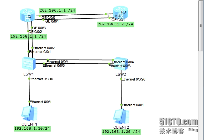
配置思路
采用如下的思路配置静态LACP模式链路聚合:
ü 在华为设备上创建Eth-Trunk,配置Eth-Trunk为静态LACP模式。
ü 将成员接口加入Eth-Trunk。
ü 配置系统优先级确定主动端。
ü 配置活动接口上限阈值。
ü 配置接口优先级确定活动链路
配置步骤
创建编号为1的Eth-Trunk,配置它的工作模式为静态LACP模式
# 配置R2(端口g0/0/0、g0/0/1)
<Huawei>system view
[Huawei]sysname R2
[R2]interface Eth-Trunk 1
[R2-Eth-Trunk1]mode lacp-static
[R2-Eth-Trunk1]ip address 202.106.1.1 24
[R2-Eth-Trunk1]quit
# 将端口GE0/0/0、GE0/0/1加入到Eth-Trunk 1中。
[R2]interface g0/0/1
[R2-GigabitEthernet0/0/1]eth-trunk 1
[R2-GigabitEthernet0/0/1]quit
[R2]interface g0/0/0
[R2-GigabitEthernet0/0/0]eth-trunk 1
[R2-GigabitEthernet0/0/0]quit
# 在R2上配置系统优先级为100,使其成为LACP主动端
[R2]lacp priority 100
# 在R2上配置活动接口上限阈值M为2
[R2]interface Eth-Trunk 1
[R2-Eth-Trunk1]max active-linknumber 2
[R2-Eth-Trunk1]quit
# 配置R3
<Huawei>system view
[Huawei]sysname R3
[R3]interface Eth-Trunk 1
[R3-Eth-Trunk1]mode lacp-static
[R3-Eth-Trunk1]ip address 202.106.1.2 24
[R3-Eth-Trunk1]quit
# 将端口GE0/0/0、GE0/0/1加入到Eth-Trunk 1中。
[R3]interface g0/0/0
[R3-GigabitEthernet0/0/0]eth-trunk 1
[R3-GigabitEthernet0/0/0]quit
[R3]interface g0/0/1
[R3-GigabitEthernet0/0/1]eth-trunk 1
[R3-GigabitEthernet0/0/1]quit
#在R3上指局域网的路径
检查配置结果
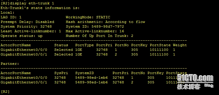
[R2]display eth-trunk 1
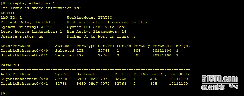
[R3]display eth-trunk 1
验证两路由之间的通信
R2和R3的Eth-Trunk接口能够互相Ping通。
[R2]ping 202.106.1.1
PING 202.106.1.1: 56 data bytes, press CTRL_C to break
Reply from 202.106.1.1: bytes=56 Sequence=1 ttl=255 time=50 ms
Reply from 202.106.1.1: bytes=56 Sequence=2 ttl=255 time=30 ms
Reply from 202.106.1.1: bytes=56 Sequence=3 ttl=255 time=30 ms
Reply from 202.106.1.1: bytes=56 Sequence=4 ttl=255 time=1 ms
Reply from 202.106.1.1: bytes=56 Sequence=5 ttl=255 time=10 ms
--- 202.106.1.1 ping statistics ---
5 packet(s) transmitted
5 packet(s) received
0.00% packet loss
round-trip min/avg/max = 1/24/50 ms
# 配置R2 (端口g0/0/2、g0/0/3)
[R2]interface Eth-Trunk 2
[R2-Eth-Trunk2]mode lacp-static
[R2-Eth-Trunk2]ip address 192.168.1.1 24
[R2-Eth-Trunk2]quit
# 将端口GE0/0/2、GE0/0/3加入到Eth-Trunk 1中。
[R2]interface g0/0/2
[R2-GigabitEthernet0/0/2]eth-trunk 2
[R2-GigabitEthernet0/0/2]quit
[R2]interface g0/0/3
[R2-GigabitEthernet0/0/3]eth-trunk 2
[R2-GigabitEthernet0/0/3]quit
在R2上配置动态NAT
[R2]acl number 2000
[R2-acl-basic-2000]
[R2-acl-basic-2000]rule permit source 192.168.1.0 0.0.0.255
[R2-acl-basic-2000]rule deny
[R2-acl-basic-2000]quit
[R2]nat address-group 1 202.106.1.3 202.106.1.10
[R2]interface Eth-Trunk 1
[R2-Eth-Trunk1]nat outbound 2000 address-group 1 no-pat
[R2-Eth-Trunk1]quit
在R3上配置回程路由
[R3]ip route-static 192.168.1.0 255.255.255.0 202.106.1.1
# 配置LSW1 (端口e0/0/1、e0/0/2)
[Huawei]sysname SW1
[SW1]interface Eth-Trunk 2
[SW1-Eth-Trunk2]mode lacp-static
[SW1-Eth-Trunk2]quit
#将端口e0/0/1、e0/0/2加入到eth-trunk 2
[SW1]interface e0/0/1
[SW1-Ethernet0/0/1]eth-trunk 2
[SW1-Ethernet0/0/1]quit
[SW1]interface e0/0/2
[SW1-Ethernet0/0/2]eth-trunk 2
[SW1-Ethernet0/0/2]quit
# 在LSW1上配置系统优先级为100,使其成为LACP主动端
[SW1]lacp priority 100
# 配置LSW1
[SW1]interface Eth-Trunk 3
[SW1-Eth-Trunk2]mode lacp-static
[SW1-Eth-Trunk2]quit
# 在LSW1上配置活动接口上限阈值M为2
[SW1]interface Eth-Trunk 3
[SW1-Eth-Trunk3]max active-linknumber 2
[SW1-Eth-Trunk3]quit
#将端口e0/0/3、e0/0/4加入到eth-trunk 3
[SW1]interface e0/0/3
[SW1-Ethernet0/0/3]eth-trunk 3
[SW1-Ethernet0/0/3]quit
[SW1]interface e0/0/4
[SW1-Ethernet0/0/4]eth-trunk 3
[SW1-Ethernet0/0/4]quit
# 配置LSW12
<Huawei>system-view
[Huawei]sysname SW2
[SW2]interface Eth-Trunk 3
[SW2-Eth-Trunk3]mode lacp-static
[SW2-Eth-Trunk3]quit
#将端口e0/0/3、e0/0/4加入到eth-trunk 2
[SW2]interface e0/0/3
[SW2-Ethernet0/0/3]eth-trunk 3
[SW2-Ethernet0/0/3]quit
[SW2]interface e0/0/4
[SW2-Ethernet0/0/4]eth-trunk 3
[SW2-Ethernet0/0/4]quit
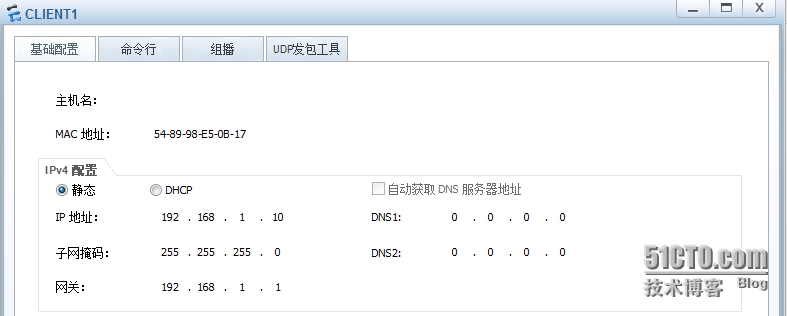
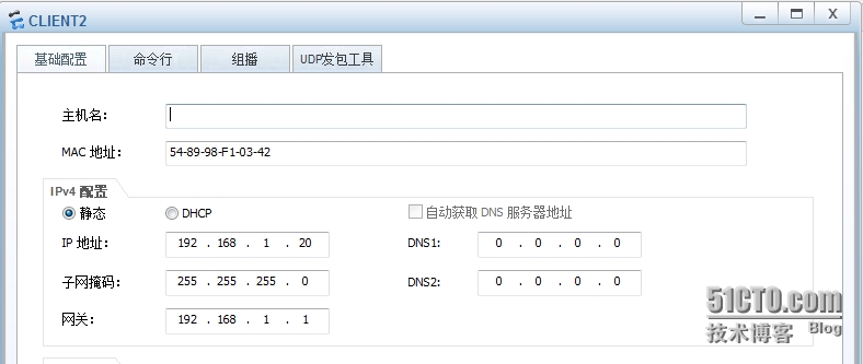
#给PC配IP
验证
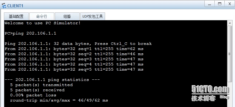
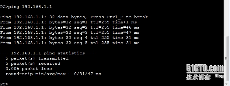
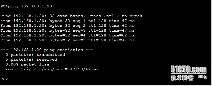
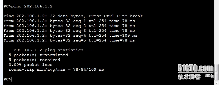
用PC1验证
Ping 网关
PingPC2
ping远端路由
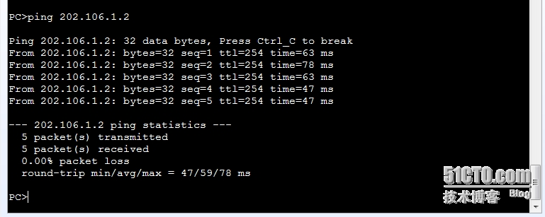
用PC2验证
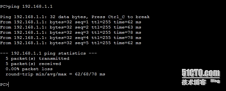
Ping 远端路由
end