mini2440_pwm.c 分析(PWM 驱动)
1、概述
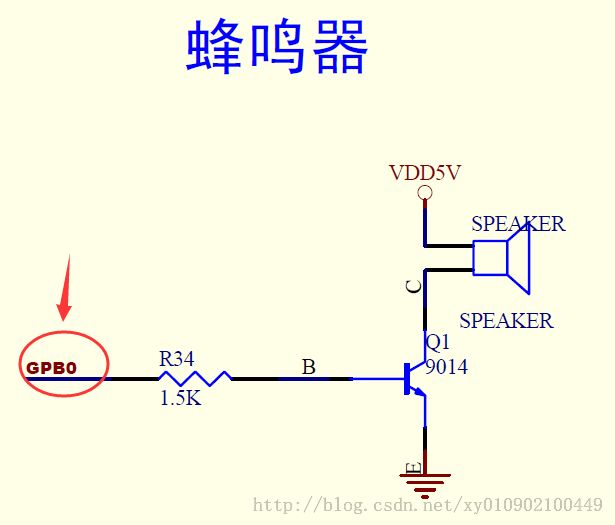
本驱动用定时器0产生PWM脉冲信号,GPB0管脚输出接蜂鸣器。
mini2440共有5个定时器,不过只有Timer 0~4具有PWM功能
2、驱动程序
#include <linux/module.h>
#include <linux/kernel.h>
#include <linux/fs.h>
#include <linux/init.h>
#include <linux/delay.h>
#include <linux/poll.h>
#include <linux/interrupt.h>
#include <linux/gpio.h>
#include <asm/irq.h>
#include <asm/io.h>
#include <asm/uaccess.h>
#include <mach/regs-gpio.h>
#include <mach/hardware.h>
#include <plat/regs-timer.h>
#include <mach/regs-irq.h>
#include <asm/mach/time.h>
#include <linux/clk.h>
#include <linux/cdev.h>
#include <linux/device.h>
#include <linux/miscdevice.h>

#define DEVICE_NAME    "pwm"

#define PWM_IOCTL_SET_FREQ              1    //设置pwm的频率
#define PWM_IOCTL_STOP                  0    //停止pwm

 //定义信号量,此处的信号量是一个互斥信号量,用于PWM设备之多只能被一个进程打开
static struct semaphore lock;


/* freq:  pclk/50/16/65536 ~ pclk/50/16
  * if pclk = 50MHz, freq is 1Hz to 62500Hz
  * human ear : 20Hz~ 20000Hz
  主要是对操作pwm的寄存器进行设置,跟裸机的设置一样,
  但是可以看出,驱动程序中设置寄存器都是采用读、修改、写的方式进行的。
  */

static void PWM_Set_Freq( unsigned long freq )
{
	unsigned long tcon;
    unsigned long tcnt;
    unsigned long tcfg1;
    unsigned long tcfg0;
    struct clk *clk_p;
    unsigned long pclk;

    //set GPB0 as tout0, pwm output
    s3c2410_gpio_cfgpin(S3C2410_GPB(0), S3C2410_GPB0_TOUT0);//设置GPB0为tout0,pwm输出
    tcon  = __raw_readl(S3C2410_TCON);         //读取寄存器TCON到tcon
    tcfg1 = __raw_readl(S3C2410_TCFG1);        //读取寄存器TCFG1到tcfg1
    tcfg0 = __raw_readl(S3C2410_TCFG0);        //读取寄存器TCFG0到tcfg0

    //prescaler = 50
    //清除prescaler 0 [7:0]位
    tcfg0 &= ~S3C2410_TCFG_PRESCALER0_MASK;  // S3C2410_TCFG_PRESCALER0_MASK定时器0和1的预分频值的掩码,TCFG[0~8]
    //设置prescaler 0 [7:0]位
    tcfg0 |= (50 - 1);   // 预分频为50HZ

    //mux = 1/16 详细请看数据手册
    tcfg1 &= ~S3C2410_TCFG1_MUX0_MASK;     //S3C2410_TCFG1_MUX0_MASK定时器0分割值的掩码:TCFG1[0~3]

    tcfg1 |= S3C2410_TCFG1_MUX0_DIV16;    //定时器0进行16分割
    __raw_writel(tcfg1, S3C2410_TCFG1);   //把新配置tcfg1的值写到分割寄存器S3C2410_TCFG1中
    __raw_writel(tcfg0, S3C2410_TCFG0);   //把tcfg0的值写到预分频寄存器S3C2410_TCFG0中

    clk_p = clk_get(NULL, "pclk");       //得到pclk
    pclk = clk_get_rate(clk_p);
    tcnt = (pclk/50/16)/freq;           //得到定时器的输入时钟,进而设置PWM的调制频率

    __raw_writel(tcnt, S3C2410_TCNTB(0));   //PWM脉宽调制的频率等于定时器的输入时钟
    __raw_writel(tcnt/2, S3C2410_TCMPB(0)); //占空比是50% ,自己认为是高电平时间

	//配置定时器
    tcon &= ~0x1f;//清空前4位
    tcon |= 0xb;   //disable deadzone, auto-reload, inv-off, update TCNTB0&TCMPB0, start timer 0
    __raw_writel(tcon, S3C2410_TCON);

    tcon &= ~2;    //clear manual update bit
    __raw_writel(tcon, S3C2410_TCON);   //把tcon写到计数器控制寄存器S3C2410_TCON中
}

static void PWM_Stop(void)
{
	s3c2410_gpio_cfgpin(S3C2410_GPB(0), S3C2410_GPIO_OUTPUT); //设置GPB0为输出
	s3c2410_gpio_setpin(S3C2410_GPB(0), 0); //设置GPB0为低电平,使蜂鸣器停止
}

static int s3c24xx_pwm_open(struct inode *inode, struct file *file)
{
	if (!down_trylock(&lock))//判断是否设备已经打开,已打开返回EBUSY
		return 0;           //是否获得信号量,是down_trylock(&lock)=0,否则非0
	else
		return -EBUSY;
}

static int s3c24xx_pwm_close(struct inode *inode, struct file *file)
{
	PWM_Stop();//停止PWM
	up(&lock);//释放信号量
    return 0;
}

/*这个pwm驱动的基本功能体现在ioctl方法上
可以看出,只提供两个选项,一个是设置频率(调用PWM_Set_Freq函数),
一个是停止。其他的功能都没有,这充分体现驱动程序中 “提供机制而不是提供策略”的思想,
驱动程序中只提供基本的功能实现,其他复杂的功能由应用程序提供。*/

static int s3c24xx_pwm_ioctl(struct inode *inode, struct file *file, unsigned int cmd, unsigned long arg)
{
	//printk("ioctl pwm: %x %lx\n", cmd, arg);
	switch (cmd) {
	case PWM_IOCTL_SET_FREQ:
		if (arg == 0){
			return -EINVAL;
		}
		PWM_Set_Freq(arg);//设置频率
		break;

	case PWM_IOCTL_STOP:
		PWM_Stop();
		break;
	}
	return 0;
}

/*初始化设备的文件操作的结构体*/
static struct file_operations dev_fops = {
	.owner   =  THIS_MODULE,
    .open    =  s3c24xx_pwm_open,
    .release =  s3c24xx_pwm_close,
    .ioctl   =  s3c24xx_pwm_ioctl,
};

static struct miscdevice misc = {
	.minor = MISC_DYNAMIC_MINOR,
	.name  = DEVICE_NAME,
	.fops  = &dev_fops,
};

/*pwm驱动也是作为杂项设备注册的,同样为了防止并发造成的竞态,有个信号量保护。模块的初始化函数
  这个函数就是初始化了一个信号量,然后调用misc_register注册到杂项设备*/
static int __init dev_init(void)
{
	int ret;
	init_MUTEX(&lock);	//初始化一个互斥锁
	ret = misc_register(&misc);
	printk (DEVICE_NAME"\tinitialized\n");
	return ret;
}

static void __exit dev_exit(void)
{
    misc_deregister(&misc);
}

module_init(dev_init);
module_exit(dev_exit);
MODULE_LICENSE("GPL");
MODULE_AUTHOR("FriendlyARM Inc.");
MODULE_DESCRIPTION("S3C2410/S3C2440 PWM Driver");
3、测试程序

