生成 Draw2d 图形
一个实例
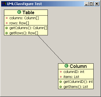
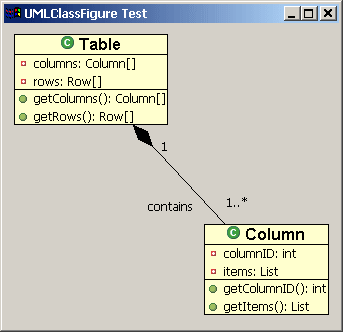
这篇文章的最终目的就是生成如下的一个图形,它是一个简单的UML类图:设计图形
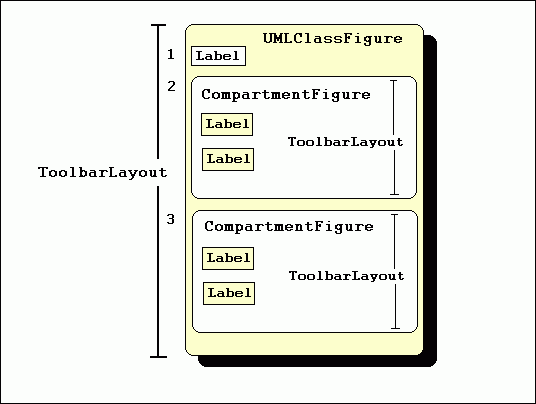
创建 CompartmentFigure 类
public class CompartmentFigure extends Figure {

  public CompartmentFigure() {
    ToolbarLayout layout = new ToolbarLayout();
    layout.setMinorAlignment(ToolbarLayout.ALIGN_TOPLEFT);
    layout.setStretchMinorAxis(false);
    layout.setSpacing(2);
    setLayoutManager(layout);
    setBorder(new CompartmentFigureBorder());
  }

  public class CompartmentFigureBorder extends AbstractBorder {
    public Insets getInsets(IFigure figure) {
      return new Insets(1,0,0,0);
    }
    public void paint(IFigure figure, Graphics graphics, Insets insets) {
      graphics.drawLine(getPaintRectangle(figure, insets).getTopLeft(),
                        tempRect.getTopRight());
    }
  }
}
						创建UMLClassFigure类
						UMLClassFigure类和前面的类在很多地方都相似。它包括3个子图形------
						两个CompartmentFigures分别装属性和方法,一个Draw2d Label显示类的名称。
						它同样使用垂直的ToolbarLayout 布局来放置它的子图形。
						UMLClassFigure使用Draw2d的Lineborder在它边上绘制一个边框。代码如下:
public class UMLClassFigure extends Figure {
  public static Color classColor = new Color(null,255,255,206);
  private CompartmentFigure attributeFigure = new CompartmentFigure();
  private CompartmentFigure methodFigure = new CompartmentFigure();
  public UMLClassFigure(Label name) {
    ToolbarLayout layout = new ToolbarLayout();
    setLayoutManager(layout);
    setBorder(new LineBorder(ColorConstants.black,1));
    setBackgroundColor(classColor);
    setOpaque(true);

    add(name);
    add(attributeFigure);
    add(methodFigure);
  }
  public CompartmentFigure getAttributesCompartment() {
    return attributeFigure;
  }
  public CompartmentFigure getMethodsCompartment() {
    return methodFigure;
  }
}
增加连接线
Draw2d offers a special type of figure, called a connection, for connecting two figures. To create a connection in Draw2d, it is first necessary to establish the two endpoints of the connection. These endpoints are called the source and the target anchors. Endpoints are created using objects that implement the ConnectionAnchor interface. Once these anchors are created, they are set as endpoints via calls to the connection's setSourceAnchor(ConnectionAnchor) and setTargetAnchor(ConnectionAnchor) methods. This is demonstrated below using a ChopboxAnchor. This type of anchor places the connection endpoint on the edge of the figure and causes it to point towards the figure's center.
Draw2d提供一个特殊类型的图形,称作连接,用来连接两个图形。在Draw2d中创建一个连接,第一步要做的是需要两个端点。这些端点称作源锚点和目的锚点。端点使用一个实现ConnectionAnchor接口对象来创建。一旦这些锚点被创建,它们通过调用connection对象的setSourceAnchor和setTargetAnchor方法被设置成端点。下面是使用ChopboxAnchor的实现。这个类型的锚点,能把connection的端点放到图形的边界上。
PolylineConnection c = new PolylineConnection(); ChopboxAnchor sourceAnchor = new ChopboxAnchor(classFigure); ChopboxAnchor targetAnchor = new ChopboxAnchor(classFigure2); c.setSourceAnchor(sourceAnchor); c.setTargetAnchor(targetAnchor); |
The following code demonstrates the addition of a connection:
为连接增加装饰物
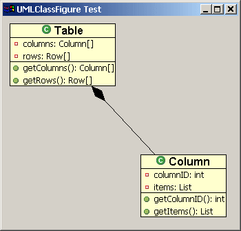
Draw2d提供了端点的修饰,比如箭头。在UML主题中,我们需要创建一个修饰物来表示一个对应关系。这将要使用到PolygonDecoration,它默认的形状是一个被填充了的箭头,但是你可以PointList创建新的修饰模板,然后调用PolygonDecoration的 setTemplate(PointList) 方法。
PolygonDecoration decoration = new PolygonDecoration(); PointList decorationPointList = new PointList(); decorationPointList.addPoint(0,0); decorationPointList.addPoint(-2,2); decorationPointList.addPoint(-4,0); decorationPointList.addPoint(-2,-2); decoration.setTemplate(decorationPointList); c.setSourceDecoration(decoration); |
使用Locators为连接增加Labels:
In addition to decorations, it is possible to add other Draw2d figures to the connection itself. This is done by calling the connection's add(IFigure figure, Object constraint) method where 'figure' is the figure that you wish to add, and 'constraint' is an object that implements the Locator interface. The Locator places the figure on the connection. We will use this technique to add labels to our class diagram. The ConnectionEndpointLocator will be used for these labels. This locator places its figure relative to the connection's source or target endpoint. It allows the user to define the distance that the figure will appear relative to the end point via its setUDistance(int) and setVDistance(int) methods. (uDistance is the distance from the connection's owner to the figure. vDistance is the distance from the figure to the connection itself).
在加入装饰物时,可以为连接增加Draw2d图形。这通过调用连接的 add(IFigure figure, Object constraint) 方法完成,constraint是一个实现了Locator接口的对象。Locator把图形放置在连接上面。我们将使用这个技术来加入labels。我们使用ConnectionEndpointLocator 来放置这些lables。看它的名字就知道,这个locator把图形放置在连接的端点附近。它允许使用者定义和端点之间的距离通过设置它自己的setUDistance(int) 和 setVDistance(int) 方法。(UDistance是连接本身和图形的距离,vDistancs是图形本身到连接的距离)。
ConnectionEndpointLocator targetEndpointLocator =
            new ConnectionEndpointLocator(c, true);
targetEndpointLocator.setVDistance(15);
Label targetMultiplicityLabel = new Label("1..*");
c.add(targetMultiplicityLabel, targetEndpointLocator);
ConnectionEndpointLocator sourceEndpointLocator =
            new ConnectionEndpointLocator(c, false);
sourceEndpointLocator.setVDistance(15);
Label sourceMultiplicityLabel = new Label("1");
c.add(sourceMultiplicityLabel, sourceEndpointLocator);

ConnectionEndpointLocator relationshipLocator =
            new ConnectionEndpointLocator(c,true);
relationshipLocator.setUDistance(30);
relationshipLocator.setVDistance(-20);
Label relationshipLabel = new Label("contains");
c.add(relationshipLabel,relationshipLocator);
|
创建一个测试类
这个类包含了一个main方法,产生一个SWT 的shell,放置一个Draw2 LightweightSystem到这个shell上。这个Lig类提供了LightweightSystem 提供了SWT和Draw2d直接的连接。这个测试类创建一个Draw2d图形作为LightweightSystem 的内容,并且为这个图形增加了两个UMLClassFigures。然后它把这两个类的图形用一个polyline连接 连接起来,加入一个 diamond polygon 的装饰器,并且加入了UML关系标签。
这个类使用如下图片: { ![]()
![]()
![]() }. 下载它们并把它们放置到你java项目的根目录即可:(自己点右键另存为即可)
}. 下载它们并把它们放置到你java项目的根目录即可:(自己点右键另存为即可)
import org.eclipse.draw2d.*;
import org.eclipse.draw2d.geometry.PointList;
import org.eclipse.draw2d.geometry.Rectangle;
import org.eclipse.swt.SWT;
import org.eclipse.swt.graphics.Font;
import org.eclipse.swt.graphics.Image;
import org.eclipse.swt.widgets.Display;
import org.eclipse.swt.widgets.Shell;

/**
 * A test class to display a UMLFigure
 */
public class UMLClassFigureTest {
 public static void main(String args[]){
	Display d = new Display();
	final Shell shell = new Shell(d);
	shell.setSize(400, 400);
	shell.setText("UMLClassFigure Test");
	LightweightSystem lws = new LightweightSystem(shell);
	Figure contents = new Figure();
	XYLayout contentsLayout = new XYLayout();
	contents.setLayoutManager(contentsLayout);

	Font classFont = new Font(null, "Arial", 12, SWT.BOLD);
	Label classLabel1 = new Label("Table", new Image(d,
		UMLClassFigureTest.class.getResourceAsStream("class_obj.gif")));
	classLabel1.setFont(classFont);

	Label classLabel2 = new Label("Column", new Image(d,
	        UMLClassFigureTest.class.getResourceAsStream("class_obj.gif")));
	classLabel2.setFont(classFont);

	final UMLClassFigure classFigure = new UMLClassFigure(classLabel1);
	final UMLClassFigure classFigure2 = new UMLClassFigure(classLabel2);

	Label attribute1 = new Label("columns: Column[]", new Image(d,
		UMLClassFigure.class.getResourceAsStream("field_private_obj.gif")));
	Label attribute2 = new Label("rows: Row[]", new Image(d,
		UMLClassFigure.class.getResourceAsStream("field_private_obj.gif")));
	Label attribute3 = new Label("columnID: int", new Image(d,
		UMLClassFigure.class.getResourceAsStream("field_private_obj.gif")));
	Label attribute4 = new Label("items: List", new Image(d,
		UMLClassFigure.class.getResourceAsStream("field_private_obj.gif")));

	classFigure.getAttributesCompartment().add(attribute1);
	classFigure.getAttributesCompartment().add(attribute2);
	classFigure2.getAttributesCompartment().add(attribute3);
	classFigure2.getAttributesCompartment().add(attribute4);

	Label method1 = new Label("getColumns(): Column[]", new Image(d,
		UMLClassFigure.class.getResourceAsStream("methpub_obj.gif")));
	Label method2 = new Label("getRows(): Row[]", new Image(d,
		UMLClassFigure.class.getResourceAsStream("methpub_obj.gif")));
	Label method3 = new Label("getColumnID(): int", new Image(d,
		UMLClassFigure.class.getResourceAsStream("methpub_obj.gif")));
	Label method4 = new Label("getItems(): List", new Image(d,
		UMLClassFigure.class.getResourceAsStream("methpub_obj.gif")));

	classFigure.getMethodsCompartment().add(method1);
	classFigure.getMethodsCompartment().add(method2);
	classFigure2.getMethodsCompartment().add(method3);
	classFigure2.getMethodsCompartment().add(method4);

	contentsLayout.setConstraint(classFigure, new Rectangle(10,10,-1,-1));
	contentsLayout.setConstraint(classFigure2, new Rectangle(200, 200, -1, -1));

	/* Creating the connection */
	PolylineConnection c = new PolylineConnection();
	ChopboxAnchor sourceAnchor = new ChopboxAnchor(classFigure);
	ChopboxAnchor targetAnchor = new ChopboxAnchor(classFigure2);
	c.setSourceAnchor(sourceAnchor);
	c.setTargetAnchor(targetAnchor);

	/* Creating the decoration */
	PolygonDecoration decoration = new PolygonDecoration();
	PointList decorationPointList = new PointList();
	decorationPointList.addPoint(0,0);
	decorationPointList.addPoint(-2,2);
	decorationPointList.addPoint(-4,0);
	decorationPointList.addPoint(-2,-2);
	decoration.setTemplate(decorationPointList);
	c.setSourceDecoration(decoration);

	/* Adding labels to the connection */
	ConnectionEndpointLocator targetEndpointLocator =
	        new ConnectionEndpointLocator(c, true);
	targetEndpointLocator.setVDistance(15);
	Label targetMultiplicityLabel = new Label("1..*");
	c.add(targetMultiplicityLabel, targetEndpointLocator);

	ConnectionEndpointLocator sourceEndpointLocator =
		new ConnectionEndpointLocator(c, false);
	sourceEndpointLocator.setVDistance(15);
	Label sourceMultiplicityLabel = new Label("1");
	c.add(sourceMultiplicityLabel, sourceEndpointLocator);

	ConnectionEndpointLocator relationshipLocator =
		new ConnectionEndpointLocator(c,true);
	relationshipLocator.setUDistance(10);
	relationshipLocator.setVDistance(-20);
	Label relationshipLabel = new Label("contains");
	c.add(relationshipLabel,relationshipLocator);

	contents.add(classFigure);
	contents.add(classFigure2);
	contents.add(c);

	lws.setContents(contents);
	shell.open();
	while (!shell.isDisposed())
		while (!d.readAndDispatch())
			d.sleep();
 }
} |


