从零开始学习OpenGL ES之一 – 基本概念
我曾写过一些文章介绍iPhone OpenGL ES编程,但大部分针对的是已经至少懂得一些3D编程知识的人。
作为起点,请下载我的OpenGL Xcode项目模板 ,而不要使用Apple提供的模板。你可以解压到下面位置安装此模板:
/Developer/Platforms/iPhoneOS.platform/Developer/Library/Xcode/Project Templates/Application/
已经有大量有关OpenGL的好教程和书籍。但是,却没有多少是关于OpenGL ES,而且没有(至少在我撰写此文时)是专门针对学习iPhone上3D编程的。因为大部分有关学习OpenGL的材料是从所谓“直接模式(direct mode )”开始的,而OpenGL ES并不支持此模式,对于没有3D背景知识的iPhone开发者而言,使用现有的书籍和教程是十分困难的。为满足一些开发者的要求,我决定撰写一个针对3D初学者的博文系列。这是此系列的第一篇文章。
OpenGL 数据类型
首先我们要讨论的是OpenGL的数据类型。因为OpenGL是一个跨平台的API,数据类型的大小会随使用的编程语言以及处理器(64位,32 位,16位)等的不同而不同,所以OpenGL定义了自己的数据类型。当传递数据到OpenGL时,你应该坚持使用这些OpenGL的数据类型,从而保证 传递数据的尺寸和精度正确。不这样做的后果是可能会导致无法预料的结果或由于运行时的数据转换造成效率低下。不论平台或语言实现的OpenGL都采用这种 方式定义数据类型以保证在各平台上数据的尺寸一致,并使平台间OpenGL代码移植更为容易。
下面是OpenGL的各种数据类型:
- GLenum : 用于GL枚举的无符号整型。通常用于通知OpenGL由指针传递的存储于数组中数据的类型(例如,GL_FLOAT用于指示数组由GLfloat组成)。
- GLboolean : 用于单布尔值。OpenGL ES还定义了其自己的“真”和“假”值(GL_TRUE和GL_FALSE)以避免平台和语言的差别。当向OpenGL传递布尔值时,请使用这些值而不是 使用YES或NO(尽管由于它们的定义实际没有区别,即使你不小心使用了YES或NO。但是,使用GL-定义值是一个好的习惯。)
- GLbitfield : 用于将多个布尔值(最多32个)打包到单个使用位操作变量的四字节整型。我们将在第一次使用位域变量时详细介绍,请参阅 wikipedia
- GLbyte : 有符号单字节整型,包含数值从-128 到 127
- GLshort : 有符号双字节整型,包含数值从−32,768 到 32,767
- GLint : 有符号四字节整型,包含数值从−2,147,483,648 到 2,147,483,647
- GLsizei : 有符号四字节整型,用于代表数据的尺寸(字节),类似于C中的size_t
- GLubyte : 无符号单字节整型,包含数值从0 到 255。
- GLushort : 无符号双字节整型,包含数值从0 到 65,535
- GLuint : 无符号四字节整型,包含数值从0 到 4,294,967,295
- GLfloat : 四字节精度IEEE 754-1985 浮点数
- GLclampf : 这也是四字节精度浮点数,但OpenGL使用GLclampf特别表示数值为0.0 到 1.0
- GLvoid : void值用于指示一个函数没有返回值,或没有参数
- GLfixed : 定点数 使用整型数存储实数。由于大部分计算机处理器在处理整型数比处理浮点数快很多,这通常是对3D系统的优化方式。但因为iPhone具有用于浮点运算的矢量处理器,我们将不讨论定点运算或GLfixed数据类型。
- GLclampx : 另一种定点型,用于使用定点运算来表示0.0 到 1.0之间的实数。正如GLfixed ,我们不会讨论或使用它。
OpenGL ES (至少iPhone目前所使用的版本)不支持8字节(64位)数据类型,如long或double。OpenGL 其实具有这些大型数据类型,但考虑到大部分嵌入式设备屏幕尺寸以及可能为它们所写的程序类型而且使用它们有可能对性能造成不利的影响,最后的决定是在 OpenGL ES中排除这些数据类型。
点或顶点
3D图像的最小单位称为 点(point) 或者 顶点vertex 。它们代表三维空间中的一个点并用来建造更复杂的物体。多边形就是由点构成,而物体是由多个多边形组成。尽管通常OpenGL支持多种多边形,但OpenGL ES只支持三边形(即三角形)。
如果你回忆高中学过的几何学,你可能会记得所谓笛卡尔坐标 。 基本概念是在空间中任选一点,称作原点 。 然后你可以通过参照原点并使用三个代表三维的数值指定空间中的任意一点,坐标是由三个想象的通过原点线表示的。从左至右的想象直线叫x-轴。沿着x-轴从 左至右数值变大,向左移动数值变小。原点左方x为负值,右边为正值。另外两轴同理。沿y轴向上,y值增加,向下y值减小。原点上方y为正,原点下方为负。 对于z轴,当物体离开观察者,数值变小,向观察者移动(或超出观察者),数值变大。原点前方z值为正,原点之后为负。下图帮助说明了这一点:
Note: iPhone上另一种绘图框架Core Graphics使用了稍微不同的坐标系统,当向屏幕上方移动时y值减小,而向下移动y值增加。
沿各轴增加或减小的数值是以任意刻度进行的 – 它们不代表任何真实单位,如英尺,英寸或米等。你可以选择任何对你的程序有意义的刻度。如果你想设计的游戏以英尺为单位,你可以那样做。如果你希望单位为 毫米,同样可行。OpenGL不管它对最终用户代表什么,只是将它作为单位处理,保证它们具有相同的距离。
由于任何物体在三维空间中的方位可以由三个数值表示,物体的位置通常在OpenGL中由使用一个三维数组的三个GLfloat变量表示,数组中的第 一项(索引0)为x位置,第二项(索引1)为y位置,第三项(索引2)为z位置。下面是一个创建OpenGL ES顶点的简单例子:
    GLfloat vertex[ 3 ]
;

    vertex[ 0 ]
 = 10.0
;       // x

    vertex[ 1 ]
 = 23.75
;      // y

    vertex[ 2 ]
 = -12.532
;    // z
在OpenGL ES中,通常将场景中所有构成所有或部分物体的提交为顶点数组 。一个顶点数组是包括场景中部分 或所有顶点数据的简单数组。我将在系列的下一篇教程中讨论,有关顶点数组要记住的是它们的大小是基于呈现的顶点数乘以三(三维空间绘图)或二(二维空间绘 图)。所以一个包含六个三维空间中的三角形的顶点数组由54个GLfloat组成,因为每个三角形有三个顶点,而每个顶点有三个坐标,即6 x 3 x 3 = 54。
处理所有这些GLfloat 是很痛苦的事情。幸运的是,有一个容易的方法。我们可以定义一个数据结构了保存多个顶点,像这样:
typedef
 struct
 {
 GLfloat x;
 GLfloat y;
 GLfloat z;
 }
 Vertex3D;
通过这样做,我们的代码可读性更强:
Vertex3D vertex;

vertex.x = 10.0
;

vertex.y = 23.75
;

vertex.z = -12.532
;
现在由于Vertex3D由三个 GLfloat 组成,向Vertex3D传递指针与向数组传递一个包含三个 GLfloat 的 数组的指针完全一样。对于电脑而言毫无分别;两者具有同样的尺寸和同样的字节数以及OpenGL需要的同样的顺序。将数据分组到数据结构只是让程序员感到 更容易,处理起来更方便。如果你下载了文章开头处的Xcode模板,你会发现此数据结构以及我后面将讨论的各种函数都定义在文件OpenGLCommon.h 中。还有一个内联函数用于创建单个顶点:
static
 inline
 Vertex3D  Vertex3DMake (CGFloat inX, CGFloat inY, CGFloat inZ)
 {
 Vertex3D ret;
 ret.x = inX;
 ret.y = inY;
 ret.z = inZ;
 return ret;
 }
如果你回忆起几何学(如果不记得也不要紧)的内容,你会知道空间中两点间的距离是使用下面公式计算的:
我们可以在一个简单的内联函数中实现这个公式来计算三维空间中任何两点间的直线距离:
static
 inline
 GLfloat  Vertex3DCalculateDistanceBetweenVertices (Vertex3D first, Vertex3D second)
 {
 GLfloat deltaX = second.x - first.x ;
 GLfloat deltaY = second.y - first.y ;
 GLfloat deltaZ = second.z - first.z ;
 return   sqrtf (deltaX*deltaX + deltaY*deltaY + deltaZ*deltaZ );
 }
;
三角形
由于OpenGL ES仅支持三角形,因此我们可以通过创建一个数据结构将三个顶点组合成一个三角形物体。
typedef
 struct
 {
 Vertex3D v1;
 Vertex3D v2;
 Vertex3D v3;

 }
 Triangle3D;
一个 Triangle3D实际上与一个九个GLfloat构成的数组是完全一样的,因为我们通过顶点和三角形而不是GLfloat数组来构建物体,所以它能帮助我们更容易地处理我们的代码。
然而关于三角形你需要知道更多的事情。在OpenGL中有一个概念叫卷绕(winding) , 它表示顶点绘制的次序是重要的。不像真实世界中的物体,OpenGL中的多边形通常都不会有两面。它们只有一面,被当做front face(前面), 三角形只有其front face面对观察者时才可见。可以设置OpenGL将多边形作为两面处理,但默认状态下,三角形只有一个可见面。通过知道哪一个面是多边形的前面或可见面,才能使OpenGL只做一半的计算。
尽管有时多边形也可以独立存在,需要绘制其背面,但通常三角形是一个大物体的一部分,其面对物体内部的一面永远也不可见。不被绘制的一面称为backface(背面) ,OpenGL是通过观察顶点的绘制次序来确定front face和backface的。以反时针次序绘制顶点的构成的面是frontface(默认,可以改变)。由于OpenGL可以很容易确定哪个三角形对用户可见,所以它使用了一种称为Backface Culling(隐面消除) 的技术来避免绘制视窗中多边形的不可见面。下一篇文章将讨论视窗,现在你可将其想象成一个虚拟摄像或观察OpenGL世界的虚拟窗口。
上图中,左边青色的三角形是backface,因此将不可见。而右方的三角形是frontface,所以将被绘制。
本系列的下一篇文章将设定一个OpenGL的虚拟世界并使用Vertex3D 和 Triangle3D进行一些基本绘图。再后,我们将讨论 变换, 它使用线性代数在虚拟世界中移动物体。
I've done a number of postings on programming OpenGL ES for the iPhone, but most of the posts I've done have been targeted at people who already know at least a little bit about 3D programming.
If you haven't already done so, grab a copy of my Empty OpenGL Xcode project template. We'll use this template as a starting point rather than Apple's provided one. You can install it by copying the unzipped folder to this location:
/Developer/Platforms/iPhoneOS.platform/Developer/Library/Xcode/Project Templates/Application/
There are a number of good tutorials and books on OpenGL. Unfortunately, there aren't very many on OpenGL ES, and none (at least as I write this) that are specifically designed for learning 3D programming on the iPhone. Because most available material for learning OpenGL starts out teaching using what's called direct mode , which is part of the functionality of OpenGL that's not in OpenGL ES, it can be really hard for an iPhone dev with no 3D background to get up and running using existing books and tutorials. I've had a number of people request it, so I've decided to start a series of blog posts designed for the absolute 3D beginner. This is the first in that series. If you've read and understood my previous OpenGL postings, you will probably find this series to be a little too basic.
OpenGL Datatypes
The first thing we'll talk about are OpenGL's datatypes. Because OpenGL is a cross-platform API, and the size of datatypes can vary depending on the programming language being used as well as the underlying processor (64-bit vs. 32-bit vs 16-bit), OpenGL declares its own custom datatypes. When passing values into OpenGL, you should always use these OpenGL datatypes to make sure that you are passing values of the right size or precision. Failure to do so could cause unexpected results or slowdowns caused by data conversion at runtime. Every implementation of OpenGL, regardless of platform or language, declares the standard OpenGL datatypes in such a way that they will be the same size on every platform, making porting OpenGL code from one platform to another easier.
Here are the OpenGL ES datatypes:
- GLenum : An unsigned integer used for GL-specific enumerations. Most commonly used to tell OpenGL the type of data stored in an array passed by pointer (e.g. GL_FLOAT ) to indicate that the array is made up of GLfloat s.
- GLboolean : Used to hold a single boolean values. OpenGL ES also declares its own true and false values (GL_TRUE and GL_FALSE ) to avoid platform and language differences. When passing booleans into OpenGL, use these rather than YES or NO (though it won't hurt if you accidentally use YES or TRUE since they are actually defined the same. But, it's good form to use the GL-defined values.
- GLbitfield : These are four-byte integers used to pack multiple boolean values (up to 32) into a single variable using bitwise operators. We'll discuss this more the first time we use a bitfield variable, but you can read up on the basic idea over at wikipedia
- GLbyte : A signed, one-byte integer capable of holding a value from -128 to 127
- GLshort : A signed two-byte integer capable of holding a value between −32,768 to 32,767
- GLint : A signed four-byte integer capable of holding a value between −2,147,483,648 and 2,147,483,647
- GLsizei : A signed, four-byte integer used to represent the size (in bytes) of data, similar to size_t in C.
- GLubyte : An unsigned, one-byte integer capable of holding a value between 0 and 255.
- GLushort : An unsigned, two-byte integer capable of holding a value between 0 and 65,535
- GLuint : An unsigned, four-byte integer capable of holding a value between 0 and 4,294,967,295
- GLfloat : A four-byte precision IEEE 754-1985 floating point variable.
- GLclampf : This is also a four-byte precision floating point variable, but when OpenGL uses GLclampf , it is indicating that the value of this particular variable should always be between 0.0 and 1.0.
- GLvoid : A void value used to indicate that a function has no return value, or takes no arguments.
- GLfixed : Fixed point numbers are a way of storing real numbers using integers. This was a common optimization in 3D systems used because most computer processors are much faster at doing math with integers than with floating-point variables. Because the iPhone has vector processors that OpenGL uses to do fast floating-point math, we will not be discussing fixed-point arithmetic or the GLfixed datatype.
- GLclampx : Another fixed-point variable, used to represent real numbers between 0.0 and 1.0 using fixed-point arithmetic. Like GLfixed , we won't be using or discussing this datatype.
OpenGL ES (at least the version used on the iPhone) does not support any 8-byte (64-bit) datatypes such as long or double . OpenGL does have these larger datatypes, but given the screen size of most embedded devices, and the types of applications you are likely to be writing for them, the decision was made to exclude them from OpenGL ES under the assumption that there would be little need for them, and that their use could have a detrimental effect on performance.
The Point or Vertex
The atomic unit in 3D graphics is called the point or vertex . These represent a single spot in three dimensional space and are used to build more complex objects. Polygons are built out of these points, and objects are built out of multiple polygons. Although regular OpenGL supports many types of polygons, OpenGL ES only supports the use of three-sided polygon, (aka triangles).
If you remember back to high-school geometry, you probably remember something called Cartesian Coordinates . The basic idea is that you select an arbitrary point in space and call it the origin . You can then designate any point in space by referencing the origin and using three numbers, one for each of the three dimensions, which are represented by three imaginary lines running through the origin. The imaginary line running from left to right is called the x-axis. Traveling along the x-axis, as you go to the right along the x axis, the value gets higher and as you go to the left, they get lower. Left of the origin are negative x values, and to the right are positive x values. The other two axes work exactly the same way. Going up along the y axis, the value of y increases, and going down, it decreases. Values above the origin have a positive y value, and those below the origin have a negative y value. With z, as objects move away from the viewer, the value gets lower, and as they move toward the viewer (or continue behind the viewer), values get higher. Points that are in front of the origin have a positive z value, and those that are behind the origin have a negative z value. The following illustration might make help those words make a little more sense:
Note: Core Graphics, which is another framework for doing graphics on the iPhone uses a slightly different coordinate system in that the y axis decreases as it goes up from the origin, and increases as it goes down.
The value that increases or decreases along these axes are in an arbitrary scale - they don't represent any real measurement, like feet, inches, or meters. You can select any scale that makes sense for your own programs. If you want to design a game where each unit is a foot, you can do that. if you want to make each unit a micron, you can do that as well. OpenGL doesn't care what they represent to the end user, it just thinks of them as units, and make sure they are all equal distances.
Since any object's location in three-dimensional space can be represented by three values, an object's position is generally represented in OpenGL by the use of three GLfloat variables, usually using an array of three floats, where the first item in the array (index 0) is the x position, the second (index 1) is the y position, and the third (index 2) is the z position. Here's a very simple example of creating a vertex for use in OpenGL ES:
GLfloat vertex
;
vertex
= 10.0
; // x
vertex
= 23.75
; // y
vertex
= -12.532
; // z
In OpenGL ES, you generally submit all the vertices that make up some or all of the objects in your scene as a vertex array . A vertex array is simply an array of values (usually GLfloat s) that contains the vertex data for some or all of the objects in the world. We'll see how that process works in the next post in this series, but the thing to remember about vertex arrays is that their size is based on the number of vertices being submitted multiplied by either three (for drawing in three-dimensional space) or two (for drawing in two-dimensional space). So, a vertex array that holds six triangles in three-dimensional space would consist of an array of 54 GLfloat s, because each triangle has three vertices, and each vertex has three coordinates and 6 x 3 x 3 = 54.
Dealing with all these GLfloat s can be a pain, however, because you're constantly having to multiply things in your head and try to think of these arrays in terms of the vertices and polygons that they represent. Fortunately, there's an easier way. We can define a data structure to hold a single vertex, like this:
typedef
struct
Vertex3D;
By doing this, our code becomes much more readable:
Vertex3D vertex;

vertex.x = 10.0
;

vertex.y = 23.75
;

vertex.z = -12.532
;
Now, because our Vertex3D struct is comprised of three GLfloat s, passing a pointer to a Vertex3D is exactly the same as passing a pointer to an array of three GLfloat s. There's no difference to the computer; both have the same size and the same number of bytes in the same order as OpenGL expects them. Grouping the data into these data structures just makes it easier for us as the programmer to visualize and deal with the data. If you download my Xcode template from the beginning of this article, this data structure and the supporting functions I'm going to be discussing next have already been defined in the file named OpenGLCommon.h . There is also an inline function for creating single vertices:
static
inline
Vertex3D
If you remember back to geometry (or maybe you don't, which is okay), the distance between two points on a plane is calculated using this formula:
We can implement this formula to calculate the straight-line distance between any two points in three-dimensional space with this simple inline function:
static
inline
GLfloat
;
Triangles
Since OpenGL ES only supports triangles, we can also create a data structure to group three vertices into a single triangle object.
typedef
struct
Triangle3D;
Again, a single Triangle3D is exactly the same as an array of nine GLfloat s, it's just easier for us to deal with it in our code because we can build objects out of vertices and triangles rather than out of arrays of GLfloat s.
There are a few more things you need to know about triangles, however. In OpenGL, there is a concept known as winding , which just means that the order in which the vertices are drawn matters. Unlike objects in the real world, polygons in OpenGL do not generally have two sides to them. They have one side, which is considered the front face , and a triangle can only be seen if its front face if facing the viewer. While it is possible to configure OpenGL to treat polygons as two-sided, by default, triangles have only one visible side. By knowing which is the front or visible side of the polygon, OpenGL is able to do half the amount of calculations per polygon that it would have to do if both sides were visible.
Although there are times when a polygon will stand on its own, and you might very well want the back drawn, usually a triangle is part of a larger object, and one side of the polygon will be facing the inside of the object and will never be seen. The side that isn't drawn is called a backface , and OpenGL determines which is the front face to be drawn and which is the backface by looking at the drawing order of the vertices. The front face is the one that would be drawn by following the vertices in counter-clockwise order (by default, it can be changed). Since OpenGL can determine easily which triangles are visible to the user, it can use a process called Backface Culling to avoid doing work for polygons that aren't facing the front of the viewport and, therefore, can't be seen. We'll discuss the viewport in the next posting, but you can think of it as the virtual camera, or virtual window looking into the OpenGL world.
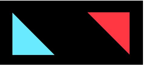
In the illustration above, the cyan triangle on the left is a backface and won't be drawn because the order that the vertices would be drawn in relation to the viewer is clockwise. On the other hand, the triangle on the right is a frontface that will be drawn because the order of the vertices is counter-clockwise in relation to the viewer.
In the next posting in this series, we'll look at setting up the virtual world in OpenGL and do some simple drawing using Vertex3D and Triangle3D . In the post after that, we'll look at transformations which are a way of using linear algebra to move objects around in the virtual world.