I2C协议->裸机程序->adapter驱动程序分析
开发板:mini2440
内核 :linux2.6.32.2
参考 :韦东山毕业班I2C视频教程
1、i2c协议简要分析
i2c中线是一种由 PHILIPS 公司开发的串行总线,用于连接微控制器及其外围设备,它具有以下特点。1、只有两条总线线路:一条串行数据线SDA,一条串行时钟线SCL。
2、每个连接到总线的器件都可以使用软件根据它的唯一的地址来确定。
3、传输数据的设备之间是简单的主从关系。
4、主机可以用作主机发送器或者主机接收器。
5、它是一个真正的多主机总线,两个或多个主机同时发起数据传输时,可以通过冲突检测和仲裁来防止数据被破坏。
6、串行的8位双向传输,位速在标准模式下可达 100kbit/s,在快速模式下可达400kbit/s,在高速模式下可待3.4Mbit/s。
7、片上的滤波器可以增加抗干扰能力,保证数据的完整性。
8、连接到同一总线上的IC数量只受到总线的最大电容400Pf的限制。
如上图所示,启动一个传输时,主机先发送一个S信号,然后发送8位数据。这8位数据的前7位为从机地址,第八位表示传输的方向(0表示写,1表示读),如果有数据则继续发送,最后发出P信号停止。
信号类型:
注意:正常数据传输时,SDA 在 SCL 为低电平时改变,在 SCL 为高电平时保持稳定。开始信号 S 信号:
SCL 为高电平时,SDA由高电平向低电平跳变,开始传送数据。
结束信号 P 信号:
SCL 为高电平时,SDA由低电平向高电平跳变,结束传送数据。
响应信号 ACK:
接收器在接收到8位数据后,在第9个时钟周期,拉低 SDA 电平
注意:在第9个时钟周期,发送器保持SDA为高,如果有ACK,那么第9个时钟周期SDA为低电平,如果没有为高电平,发送器根据电平高低分辨是否有ACK信号。
如果使能了IIC中断,发送完8bit数据后,主机自动进入中断处理函数,此时SCL被发送器拉低,让接收器被迫等待。恢复传输只需要清除中断挂起。
2、 s3c2440 读写流程
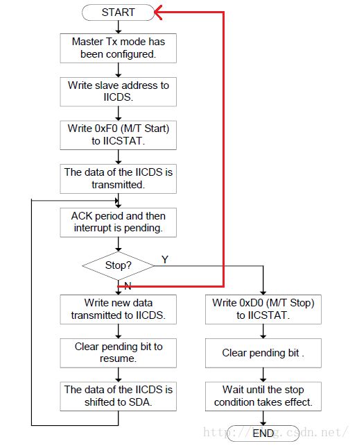
1、设置传输模式 IICSTAT[7-6],我们做实验与AT24C08通信时,2440作为主机,因此只用到主机发模式和主机收模式。2、写入从机地址到 IICDS[7-1],此时IICDS[7-1]位表示从机地址,第0位不关心。如 AT24C08 为 0xA0(最低位写0了,发送到数据线上的7位地址的后边以为才表示收发,这里虽然写0但并不是根据这里的0来真正发送的)。
3、写 0xF0(写) 或 0xB0(读)到 IICSTAT 寄存器, 高两位表示 传输模式前边设置过了,设置IICSTT[5-4] 为 11,使能传输,发送S信号。
4、IIC控制器自动将第2步中设置的 IICDS[7-1] 再根据 传输模式 补充 IICDS[0]位,发送出去。
5、进入第9个时钟周期,此时,从机决定是否发出ACK信号,主机进入中断,判断是否收到ACK信号,以及是否继续传输。
继续发送:
1、将数据写入 IICDS
2、清除中断挂起,SCL时钟恢复,IICDS的数据被自动发送到 SDA 线上,回到第5步。
停止发送:
1、写 0xD0(写) 和 0x90(读) 到 IICATAT ,IICATAT[7-6]还是表示的传输模式,IICATAT[5-4] == 0 1,发送停止信号
2、清除中断挂起,SCL时钟恢复,发出停止信号
3、延时,等待停止信号发出
3、 AT24C08 读写分析
1、写过程
写过程与2440芯片的里的写流程相一致,按照流程写就OK2、读过程
读过程是由2440芯片里的一个写流程加一个读流程组合而成,其中写流程结束没有发出P信号,而是直接发出了S信号开始读流程,也就是我为什么加了一道红线的原因。附上一份简单的裸机程序,仅供参考:基于MINI2440
#include <stdio.h>
#include "s3c2440.h"

void Delay(int time);

#define WRDATA      (1)
#define RDDATA      (2)

typedef struct tI2C {
    unsigned char *pData;   /* 数据缓冲区 */
    volatile int DataCount; /* 等待传输的数据长度 */
    volatile int Status;    /* 状态 */
    volatile int Mode;      /* 模式:读/写 */
    volatile int Pt;        /* pData中待传输数据的位置 */
}tS3C24xx_I2C, *ptS3C24xx_I2C;

static tS3C24xx_I2C g_tS3C24xx_I2C;

/*
 * I2C初始化
 */
void i2c_init(void)
{
    GPEUP  |= 0xc000;       // 禁止内部上拉
/*
 *	AT24C08 两根线 I2CSCL I2CSDA 与 2440芯片相连
 *  配置2440 GPECON GPE15 GPE14引脚为I2C功能
 */
    GPECON |= 0xa0000000;   // 选择引脚功能:GPE15:IICSDA, GPE14:IICSCL
/* 开INT_IIC中断 */
    //INTMSK &= ~(BIT_IIC);

    /* bit[7] = 1, 使能ACK
     * bit[6] = 0, IICCLK = PCLK/16
     * bit[5] = 1, 使能中断
     * bit[3:0] = 0xf, Tx clock = IICCLK/16
     * PCLK = 50MHz, IICCLK = 3.125MHz, Tx Clock = 0.195MHz
     */
    IICCON = (1<<7) | (0<<6) | (1<<5) | (0xf);  // 0xaf

    //IICADD  = 0x10;     // S3C24xx slave address = [7:1]
    IICSTAT = 0x10;     // I2C串行输出使能(Rx/Tx)
}

void I_Write(unsigned int slvaddr, unsigned char addr, unsigned char data)
{
    unsigned int ack;
	// 写从地址
	IICSTAT |= 0x1<<6;//主机写模式
    IICSTAT |= 0x1<<7;
    IICDS = slvaddr;//0xa0;  //write slave address to IICDS
    IICCON&=~0x10; //clear pending bit
    IICSTAT = 0xf0;  //(M/T start)
    while((IICCON & 1<<4) == 0);//udelay(10);//ack period and then interrupt is pending
    // 写寄存器地址
    IICDS = addr;
    IICCON&=~0x10; //clear pending bit
    while((IICCON & 1<<4) == 0);//udelay(10);//ack period and then interrupt is pending
	// 写数据
    IICDS = data;
    IICCON&=~0x10; //clear pending bit
    while((IICCON & 1<<4) == 0);//udelay(10);//ack period and then interrupt is pending
	// 发出停止信号
    IICSTAT = 0xD0; //write (M/T stop to IICSTAT)
    IICCON&=~0x10; //clear pending bit

    while((IICSTAT & 1<<5) == 1);
}
unsigned char I_Read(unsigned int slvaddr, unsigned char addr)
{
    unsigned char data  = 1;
    int ack;
	// 写从地址
	IICSTAT |= 0x1<<6;//主机写模式
    IICSTAT |= 0x1<<7;
	slvaddr = 0xA0;
    IICDS = slvaddr;//0xa0;  //write slave address to IICDS
    IICCON&=~0x10; //clear pending bit
    IICSTAT = 0xf0;  //(M/T start)
    while((IICCON & 1<<4) == 0);//udelay(10);//ack period and then interrupt is pending

    // 写寄存器地址
    IICDS = addr;
    IICCON&=~0x10; //clear pending bit
    while((IICCON & 1<<4) == 0);//udelay(10);//ack period and then interrupt is pending

    // 写从地址(读模式)
    slvaddr = 0xA1;
    IICSTAT &= ~(0x1<<6);//主机接受模式
    IICSTAT |= 0x1<<7;
    IICDS = slvaddr;
    IICCON&=~0x10; //clear pending bit
    IICSTAT = 0xb0;  //(M/R Start)
    while((IICCON & 1<<4) == 0);//udelay(10);//uart_SendByte('o');//ack period and then interrupt is pending::

	// 读数据
    data = IICDS;
    //IICCON&=~0x10; //clear pending bit
	IICCON = 0x2f;	//清挂起状态,并设置无应答
    while((IICCON & 1<<4) == 0);//udelay(10);//ack period and then interrupt is pending
    data = IICDS;

	//IICCON&=~0x10; //clear pending bit
	IICCON = 0x2f;	//清挂起状态,并设置无应答
    while((IICCON & 1<<4) == 0);//udelay(10);//ack period and then interrupt is pending


    IICSTAT = 0x90;
	IICCON = 0xaf;
    //IICCON &= ~0x10; //clear pending bit

    while((IICSTAT & 1<<5) == 1);

    return data;

}
4、adapter驱动程序
这里,我们主要分析驱动里的发送核心算法,至于注册中断,IO内存映射,设置寄存器不在讨论。
static int xxx_i2c_xfer(struct i2c_adapter *adpap, struct i2c_msg *msg,int num)
这个算法函数的作用就是将上层封装好的一些i2c_msg 进行解析,将数据写入寄存器,发送出去。在设备驱动层,我们使用了类似i2c_smbus_write_byte 等函数,类似的函数有很多,它们的作用就是封装i2c_msg 结构(比如读和写的 msg 肯定不一样,读一个字节和读多个字节也不一样),然后调用 i2c_smbus_xfer_emulated->i2c_transfer,最终调用到我们的xxx_i2c_xfer函数进行传输。通过分析i2c_smbus_xfer_emulated函数,我们可以了解i2c_msg是如何封装的。下面,我们简单分析一下,知道最上层想干什么,我们才能知道实现哪些底层的功能不是。
struct i2c_msg {
	__u16 addr;		//从机地址
	__u16 flags;
	__u16 len;		// buf 里 有多少个字节
	__u8 *buf;		// 本 msg 含有的数据,可能是1个字节,可有可能是多个字节
};
此函数,省略了很多内容,举例分析而已~,细节请看源码
static s32 i2c_smbus_xfer_emulated(struct i2c_adapter * adapter, u16 addr,
                                   unsigned short flags,
                                   char read_write, u8 command, int size,
                                   union i2c_smbus_data * data)
{
	unsigned char msgbuf0[I2C_SMBUS_BLOCK_MAX+3];
	unsigned char msgbuf1[I2C_SMBUS_BLOCK_MAX+2];
	int num = read_write == I2C_SMBUS_READ?2:1;	// 写操作两个Msg 读操作一个msg 这和我们前面分析AT24c08是一致的
	struct i2c_msg msg[2] = { { addr, flags, 1, msgbuf0 },
	                          { addr, flags | I2C_M_RD, 0, msgbuf1 }
	                        };
	msgbuf0[0] = command;	// 从机地址右移1位得到的,比如AT24C08  为 0x50
	switch(size) {
	case I2C_SMBUS_BYTE_DATA:	// 单字节读写
		if (read_write == I2C_SMBUS_READ)
			msg[1].len = 1;
			/*
			 * 读:
			 *	msgbuf0[0] = command
			 *  msg[1].len = 1	,数据会读到 msgbuf0[1] 里
			 */
		else {
			msg[0].len = 2;
			msgbuf0[1] = data->byte;
			/*
			 * 写:
			 *	msgbuf0[0] = command
			 *	msgbuf0[1] = data->byte
			 */
		}
		break;
	}
	status = i2c_transfer(adapter, msg, num);
}
上面代码跟我们分析AT24C08的时候如出一辙,对于一个写操作,我们只需要一个2440的写流程对应于这里的一个Msg,然而对于读操作,我们需要2440的两个流程,对应于这里的两个Msg。那么,我们底层控制器驱动需要做的工作就是,取出所有的Msg,将每一个Msg里buf里的数据发送出去,如果有下一个Msg, 那么再将下一个Msg里的buf发送完毕,最后发出P停止信号。还有一点,每发送一个Msg都要先发出S开始信号。
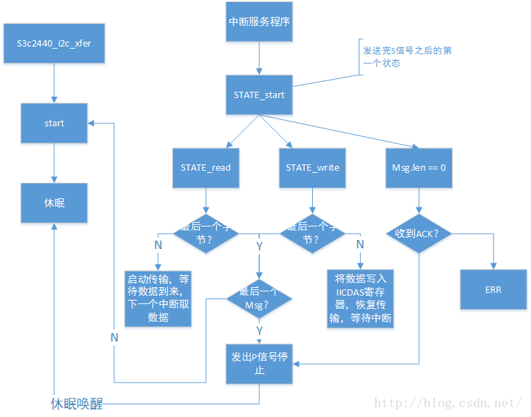
在看adapter程序之前,我们先来简单思考一下,发出S开始信号之后,可能有以下3中情况:
1、当前msg.len == 0 ,如果有ACK直接发出stop信号。这种情况出现在,控制器枚举设备的时候,因为它只发送S信号以及设备地址,不发送数据。
2、根据msg->flags 为 I2C_M_RD 等信息判断读写,msg->flags 最低位为1表示读,最低位为0表示写。
#define I2C_M_TEN0x0010 /* this is a ten bit chip address */
#define I2C_M_RD0x0001 /* read data, from slave to master */
#define I2C_M_NOSTART0x4000 /* if I2C_FUNC_PROTOCOL_MANGLING */
#define I2C_M_REV_DIR_ADDR0x2000 /* if I2C_FUNC_PROTOCOL_MANGLING */
#define I2C_M_IGNORE_NAK0x1000 /* if I2C_FUNC_PROTOCOL_MANGLING */
#define I2C_M_NO_RD_ACK0x0800 /* if I2C_FUNC_PROTOCOL_MANGLING */
#define I2C_M_RECV_LEN0x0400 /* length will be first received byte */
2.1 如果是读
恢复 IIC 传输,开始读就行了,在下一个中断里将寄存器数据取出,如果是最后一个要读取的数据,不能发送ACK(禁用ACK)。
2.2 如果是写
将数据写入 IICDS 寄存器,恢复 IIC 传输。
附上韦东山老师的程序:
看程序之前,看一个大致的流程图,对于理解程序有帮助
#include <linux/kernel.h>
#include <linux/module.h>

#include <linux/i2c.h>
#include <linux/init.h>
#include <linux/time.h>
#include <linux/interrupt.h>
#include <linux/delay.h>
#include <linux/errno.h>
#include <linux/err.h>
#include <linux/platform_device.h>
#include <linux/pm_runtime.h>
#include <linux/clk.h>
#include <linux/cpufreq.h>
#include <linux/slab.h>
#include <linux/io.h>
#include <linux/of_i2c.h>
#include <linux/of_gpio.h>
#include <plat/gpio-cfg.h>
#include <mach/regs-gpio.h>

#include <asm/irq.h>

#include <plat/regs-iic.h>
#include <plat/iic.h>

//#define PRINTK printk
#define PRINTK(...)

enum s3c24xx_i2c_state {
	STATE_IDLE,
	STATE_START,
	STATE_READ,
	STATE_WRITE,
	STATE_STOP
};

struct s3c2440_i2c_regs {
	unsigned int iiccon;
	unsigned int iicstat;
	unsigned int iicadd;
	unsigned int iicds;
	unsigned int iiclc;
};

struct s3c2440_i2c_xfer_data {
	struct i2c_msg *msgs;
	int msn_num;
	int cur_msg;
	int cur_ptr;
	int state;
	int err;
	wait_queue_head_t wait;
};

static struct s3c2440_i2c_xfer_data s3c2440_i2c_xfer_data;


static struct s3c2440_i2c_regs *s3c2440_i2c_regs;


static void s3c2440_i2c_start(void)
{
	s3c2440_i2c_xfer_data.state = STATE_START;

	if (s3c2440_i2c_xfer_data.msgs->flags & I2C_M_RD) /* 读 */
	{
		s3c2440_i2c_regs->iicds		 = s3c2440_i2c_xfer_data.msgs->addr << 1;
		s3c2440_i2c_regs->iicstat 	 = 0xb0;	// 主机接收,启动
	}
	else /* 写 */
	{
		s3c2440_i2c_regs->iicds		 = s3c2440_i2c_xfer_data.msgs->addr << 1;
		s3c2440_i2c_regs->iicstat    = 0xf0; 		// 主机发送,启动
	}
}

static void s3c2440_i2c_stop(int err)
{
	s3c2440_i2c_xfer_data.state = STATE_STOP;
	s3c2440_i2c_xfer_data.err   = err;

	PRINTK("STATE_STOP, err = %d\n", err);


	if (s3c2440_i2c_xfer_data.msgs->flags & I2C_M_RD) /* 读 */
	{
		// 下面两行恢复I2C操作,发出P信号
		s3c2440_i2c_regs->iicstat = 0x90;
		s3c2440_i2c_regs->iiccon  = 0xaf;
		ndelay(50);  // 等待一段时间以便P信号已经发出
	}
	else /* 写 */
	{
		// 下面两行用来恢复I2C操作,发出P信号
		s3c2440_i2c_regs->iicstat = 0xd0;
		s3c2440_i2c_regs->iiccon  = 0xaf;
		ndelay(50);  // 等待一段时间以便P信号已经发出
	}

	/* 唤醒 */
	wake_up(&s3c2440_i2c_xfer_data.wait);

}

static int s3c2440_i2c_xfer(struct i2c_adapter *adap,
			struct i2c_msg *msgs, int num)
{
	unsigned long timeout;

	/* 把num个msg的I2C数据发送出去/读进来 */
	s3c2440_i2c_xfer_data.msgs    = msgs;
	s3c2440_i2c_xfer_data.msn_num = num;
	s3c2440_i2c_xfer_data.cur_msg = 0;
	s3c2440_i2c_xfer_data.cur_ptr = 0;
	s3c2440_i2c_xfer_data.err     = -ENODEV;

	s3c2440_i2c_start();

	/* 休眠 */
	timeout = wait_event_timeout(s3c2440_i2c_xfer_data.wait, (s3c2440_i2c_xfer_data.state == STATE_STOP), HZ * 5);
	if (0 == timeout)
	{
		printk("s3c2440_i2c_xfer time out\n");
		return -ETIMEDOUT;
	}
	else
	{
		return s3c2440_i2c_xfer_data.err;
	}
}

static u32 s3c2440_i2c_func(struct i2c_adapter *adap)
{
	return I2C_FUNC_I2C | I2C_FUNC_SMBUS_EMUL | I2C_FUNC_PROTOCOL_MANGLING;
}


static const struct i2c_algorithm s3c2440_i2c_algo = {
//	.smbus_xfer     = ,
	.master_xfer	= s3c2440_i2c_xfer,
	.functionality	= s3c2440_i2c_func,
};

/* 1. 分配/设置i2c_adapter
 */
static struct i2c_adapter s3c2440_i2c_adapter = {
 .name			 = "s3c2440_100ask",
 .algo			 = &s3c2440_i2c_algo,
 .owner 		 = THIS_MODULE,
};

static int isLastMsg(void)
{
	return (s3c2440_i2c_xfer_data.cur_msg == s3c2440_i2c_xfer_data.msn_num - 1);
}

static int isEndData(void)
{
	return (s3c2440_i2c_xfer_data.cur_ptr >= s3c2440_i2c_xfer_data.msgs->len);
}

static int isLastData(void)
{
	return (s3c2440_i2c_xfer_data.cur_ptr == s3c2440_i2c_xfer_data.msgs->len - 1);
}

static irqreturn_t s3c2440_i2c_xfer_irq(int irq, void *dev_id)
{
	unsigned int iicSt;
    iicSt  = s3c2440_i2c_regs->iicstat;

	if(iicSt & 0x8){ printk("Bus arbitration failed\n\r"); }

	switch (s3c2440_i2c_xfer_data.state)
	{
		case STATE_START : /* 发出S和设备地址后,产生中断 */
		{
			PRINTK("Start\n");
			/* 如果没有ACK, 返回错误 */
			if (iicSt & S3C2410_IICSTAT_LASTBIT)
			{
				s3c2440_i2c_stop(-ENODEV);
				break;
			}

			if (isLastMsg() && isEndData())
			{
				s3c2440_i2c_stop(0);
				break;
			}

			/* 进入下一个状态 */
			if (s3c2440_i2c_xfer_data.msgs->flags & I2C_M_RD) /* 读 */
			{
				s3c2440_i2c_xfer_data.state = STATE_READ;
				goto next_read;
			}
			else
			{
				s3c2440_i2c_xfer_data.state = STATE_WRITE;
			}
		}

		case STATE_WRITE:
		{
			PRINTK("STATE_WRITE\n");
			/* 如果没有ACK, 返回错误 */
			if (iicSt & S3C2410_IICSTAT_LASTBIT)
			{
				s3c2440_i2c_stop(-ENODEV);
				break;
			}

			if (!isEndData())  /* 如果当前msg还有数据要发送 */
			{
				s3c2440_i2c_regs->iicds = s3c2440_i2c_xfer_data.msgs->buf[s3c2440_i2c_xfer_data.cur_ptr];
				s3c2440_i2c_xfer_data.cur_ptr++;

				// 将数据写入IICDS后,需要一段时间才能出现在SDA线上
				ndelay(50);

				s3c2440_i2c_regs->iiccon = 0xaf;		// 恢复I2C传输
				break;
			}
			else if (!isLastMsg())
			{
				/* 开始处理下一个消息 */
				s3c2440_i2c_xfer_data.msgs++;
				s3c2440_i2c_xfer_data.cur_msg++;
				s3c2440_i2c_xfer_data.cur_ptr = 0;
				s3c2440_i2c_xfer_data.state = STATE_START;
				/* 发出START信号和发出设备地址 */
				s3c2440_i2c_start();
				break;
			}
			else
			{
				/* 是最后一个消息的最后一个数据 */
				s3c2440_i2c_stop(0);
				break;
			}

			break;
		}

		case STATE_READ:
		{
			PRINTK("STATE_READ\n");
			/* 读出数据 */
			s3c2440_i2c_xfer_data.msgs->buf[s3c2440_i2c_xfer_data.cur_ptr] = s3c2440_i2c_regs->iicds;
			s3c2440_i2c_xfer_data.cur_ptr++;
next_read:
			if (!isEndData()) /* 如果数据没读写, 继续发起读操作 */
			{
				if (isLastData())  /* 如果即将读的数据是最后一个, 不发ack */
				{
					s3c2440_i2c_regs->iiccon = 0x2f;   // 恢复I2C传输,接收到下一数据时无ACK
				}
				else
				{
					s3c2440_i2c_regs->iiccon = 0xaf;   // 恢复I2C传输,接收到下一数据时发出ACK
				}
				break;
			}
			else if (!isLastMsg())
			{
				/* 开始处理下一个消息 */
				s3c2440_i2c_xfer_data.msgs++;
				s3c2440_i2c_xfer_data.cur_msg++;
				s3c2440_i2c_xfer_data.cur_ptr = 0;
				s3c2440_i2c_xfer_data.state = STATE_START;
				/* 发出START信号和发出设备地址 */
				s3c2440_i2c_start();
				break;
			}
			else
			{
				/* 是最后一个消息的最后一个数据 */
				s3c2440_i2c_stop(0);
				break;
			}
			break;
		}

		default: break;
	}

	/* 清中断 */
	s3c2440_i2c_regs->iiccon &= ~(S3C2410_IICCON_IRQPEND);

	return IRQ_HANDLED;
}


/*
 * I2C初始化
 */
static void s3c2440_i2c_init(void)
{
	struct clk *clk;

	clk = clk_get(NULL, "i2c");
	clk_enable(clk);

    // 选择引脚功能:GPE15:IICSDA, GPE14:IICSCL
    s3c_gpio_cfgpin(S3C2410_GPE(14), S3C2410_GPE14_IICSCL);
	s3c_gpio_cfgpin(S3C2410_GPE(15), S3C2410_GPE15_IICSDA);

    /* bit[7] = 1, 使能ACK
     * bit[6] = 0, IICCLK = PCLK/16
     * bit[5] = 1, 使能中断
     * bit[3:0] = 0xf, Tx clock = IICCLK/16
     * PCLK = 50MHz, IICCLK = 3.125MHz, Tx Clock = 0.195MHz
     */
    s3c2440_i2c_regs->iiccon = (1<<7) | (0<<6) | (1<<5) | (0xf);  // 0xaf

    s3c2440_i2c_regs->iicadd  = 0x10;     // S3C24xx slave address = [7:1]
    s3c2440_i2c_regs->iicstat = 0x10;     // I2C串行输出使能(Rx/Tx)
}

static int i2c_bus_s3c2440_init(void)
{
	/* 2. 硬件相关的设置 */
	s3c2440_i2c_regs = ioremap(0x54000000, sizeof(struct s3c2440_i2c_regs));

	s3c2440_i2c_init();

	request_irq(IRQ_IIC, s3c2440_i2c_xfer_irq, 0, "s3c2440-i2c", NULL);

	init_waitqueue_head(&s3c2440_i2c_xfer_data.wait);

	/* 3. 注册i2c_adapter */
	i2c_add_adapter(&s3c2440_i2c_adapter);

	return 0;
}

static void i2c_bus_s3c2440_exit(void)
{
	i2c_del_adapter(&s3c2440_i2c_adapter);
	free_irq(IRQ_IIC, NULL);
	iounmap(s3c2440_i2c_regs);
}

module_init(i2c_bus_s3c2440_init);
module_exit(i2c_bus_s3c2440_exit);
MODULE_LICENSE("GPL");


