Python3+OpenCV学习笔记(二):图像几何变换及补边、裁剪
缩放变换
缩放变换即改变图片大小,在cv2里面我们使用函数cv2.resize(fileobj, None,(fx, fy), interpolation = format)函数。“fileobj”为图片对象;“(fx, fy)”参数类型为tuple, 可以指定大小如“(640, 480)”,也可以“fx=640,fy=480”;“interpolation”为插补项,可以选择cv2.INTER_AREA(使用象素关系重采样)、cv2.INTER_LINEAR(双线性插值)、cv2.INTER_CUBIC(立方插值)等变换方法,cv2.INTER_AREA适合缩小使用,cv2.INTER_LINEAR、cv2.INTER_CUBIC(慢)适合放大使用。我们运行下面的示例,将图片放大1.5倍,看看三种方式的具体效果:
import cv2

img1 = cv2.imread('Rachel.jpg')
img2 = cv2.imread('Rachel.jpg')
img3 = cv2.imread('Rachel.jpg')

res1 = cv2.resize(img1, None, fx=1.5, fy=1.5, interpolation=cv2.INTER_AREA)
res2 = cv2.resize(img2, None, fx=1.5, fy=1.5, interpolation=cv2.INTER_LINEAR)
res3 = cv2.resize(img3, None, fx=1.5, fy=1.5, interpolation=cv2.INTER_CUBIC)

cv2.imshow('res1', res1)
cv2.imshow('res2', res2)
cv2.imshow('res3', res3)

while True:
	if (cv2.waitKey() & 0xFF) == ord('q'):
		break
	else:
		pass
cv2.destroyAllWindows()
在res1、res2、res3三个窗口中分别利用三种变换方法进行放大。可以使用鼠标滚轮进一步放大,查看更细致的区别,这里我选择了Rachel的左眼进行放大:
根据黄色矩形框内的瞳孔亮点,我们可以明显看出三种变换方法的区别。当然,也可以将图像每个像素点的值打印出来进行查看。
平移变换
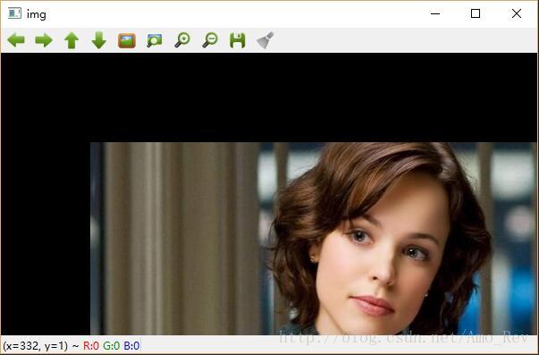
进行平移变换需要用到cv2.warpAffine(obj,matrix,(cols,rows))“matrix”为坐标变换矩阵,其变换原理如下:
Mat为一个2×3的矩阵[ [a00,a01,mox ],[a10,a11,moy ] ],像素点原始坐标为(cols,rows),下面利用Mat矩阵计算像素点变换后的坐标(newclos,newrow),其中newclos = a00*clos+a01*rows+mox,newrow = a10*cols+a11*rows+moy。
import numpy
import cv2

img = cv2.imread('Rachel.jpg')
# 获取坐标
rows, cols, channal = img.shape
# 获取变换矩阵
MAT = numpy.float32([[1, 0, 100], [0, 1, 100]])
# 平移变换
mov = cv2.warpAffine(img, MAT, (cols, rows))

cv2.imshow('img', mov)

while True:
	if (cv2.waitKey() & 0xFF) == ord('q'):
		break
	else:
		pass
cv2.destroyAllWindows()旋转变换
进行旋转变换需要用到cv2.getRotationMatrix2D(center,angle,scale)“center”确定旋转中心,“angle”确定旋转角度,“scale”可以确定图像缩放比例。
示例如下:
import cv2

img = cv2.imread('Rachel.jpg')
# 生成旋转矩阵
RotateMatrix = cv2.getRotationMatrix2D(center=(img.shape[1]/2, img.shape[0]/2), angle=90, scale=1)
RotImg = cv2.warpAffine(img, RotateMatrix, (img.shape[0]*2, img.shape[1]))
cv2.imshow('img', RotImg)仿射变换
仿射变换是一种二维坐标到二维坐标直接的线性变换,并保持二维图形的“平直性”,转换前平行的线,在转换后依然平行。对于仿射变换,我们只需要知道变换前的三个点与其对应的变换后的点,通过cv2.getAffineTransform(dst,src)函数来得到仿射变换矩阵。
示例如下:
import numpy as np
import cv2
from matplotlib import pyplot as plt

img = cv2.imread('Rachel.jpg', 1)
rows, cols, channal = img.shape

MAT1 = np.float32([[50, 50], [200, 50], [50, 200]])
MAT2 = np.float32([[10, 100], [200, 50], [100, 250]])
MAT3 = np.float32([[100, 100], [200, 50], [100, 250]])
MAT4 = np.float32([[10, 100], [100, 50], [100, 250]])
MAT5 = np.float32([[10, 100], [200, 50], [100, 150]])
# 生成4个仿射变换矩阵
M1 = cv2.getAffineTransform(MAT1, MAT2)
M2 = cv2.getAffineTransform(MAT1, MAT3)
M3 = cv2.getAffineTransform(MAT1, MAT4)
M4 = cv2.getAffineTransform(MAT1, MAT5)

dst1 = cv2.warpAffine(img, M1, (cols, rows))
dst2 = cv2.warpAffine(img, M2, (cols, rows))
dst3 = cv2.warpAffine(img, M3, (cols, rows))
dst4 = cv2.warpAffine(img, M4, (cols, rows))

plt.subplot(231), plt.imshow(img), plt.title('Input')
plt.subplot(232), plt.imshow(dst1), plt.title('Output1')
plt.subplot(233), plt.imshow(dst2), plt.title('Output2')
plt.subplot(234), plt.imshow(dst3), plt.title('Output3')
plt.subplot(235), plt.imshow(dst3), plt.title('Output3')
plt.show()
M1~M4为四个不同的仿射变换矩阵,再用cv2.warpAffine()进行仿射变换,得到如下图所示的几张图片:
注:颜色不对是由于之前提到过的RGB和BGR颜色通道差异造成的。
投影变换
投影变换,我们则需要知道四个点,通过cv2.getPerspectiveTransform()求得变换矩阵.之后使用cv2.warpPerspective()获得矫正后的图片。
示例如下:
import numpy as np
import cv2
from matplotlib import pyplot as plt

img = cv2.imread('newspaper.jpg', 1)
rows, cols, ch = img.shape
# pts1为图像上四个点
pts1 = np.float32([[26, 174], [285, 39], [280, 282], [391, 140]])
pts2 = np.float32([[0, 0], [300, 0], [0, 300], [300, 300]])

M = cv2.getPerspectiveTransform(pts1, pts2)

dst = cv2.warpPerspective(img, M, (300, 300))

plt.subplot(121), plt.imshow(img), plt.title('Input')
plt.subplot(122), plt.imshow(dst), plt.title('Output')
plt.show()进行图像操作是我们还会涉及到图像补边和裁剪多余部分的问题,话不多说,看示例:
import cv2
from matplotlib import pyplot as plt

img = cv2.imread('Rachel.jpg')
# 颜色空间转换BGR to RGB
img = cv2.cvtColor(img, cv2.COLOR_BGR2RGB)
# 获取图像尺寸并输出
cols, rows, channal = img.shape
coord = (cols, rows)
print(coord)
print(img.size)
# 将图片进行缩放变换为600*300的图片作为标准
img_standard = cv2.resize(img, (600, 300), interpolation=cv2.INTER_LINEAR)
# 在600*300的图片上下左右分别贴上宽度为50的红色区域
img_patch = cv2.copyMakeBorder(img_standard, 50, 50, 50, 50, cv2.BORDER_CONSTANT, value=(255, 0, 0))
# 裁剪一块区域,起始坐标(xi, yi)=(200, 20),终止坐标(xn, yn) = (480, 250)
img_cropped = img[20:250, 200:480]

plt.subplot(221), plt.imshow(img), plt.title('Original')
plt.subplot(222), plt.imshow(img_standard), plt.title('Standard')
plt.subplot(223), plt.imshow(img_patch), plt.title('Patch')
plt.subplot(224), plt.imshow(img_cropped), plt.title('Cropped')
plt.show()
看看效果:
参考链接:
OpenCV3.3-Doc
【opencv+python】图像处理之二、几何变换(仿射与投影)的原理


