2018蓝桥杯嵌入式备赛笔记
第七届省赛 “ 模拟液位检测“
相关文件(包括考场文件)使用 https://www.jianshu.com/p/c70ca3a02087教程上传到github上
之后写的差不多了整理一下再地址
前人的参考资料收集:http://blog.csdn.net/weixin_38412729/article/details/78631932
一、屏幕
首先例程里已经提供了屏幕使用方法
很容易就能配置
二、adc
题目中要求使用ADCAD使用方法:
该板子

R37 接在PB0 上
根据手册
PB0 连接了adc 的通道8
这是硬件连接
STM32的adc是12位的

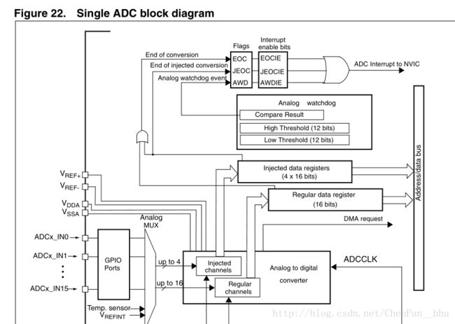
支持最多四个注入通道和16个规则通道(概念与引脚的多个输入通道不同)
主要区别在于转换顺序不同,逻辑较为复杂,使用的寄存器,中断标志也不同
在此只需要单通道即可完成工作
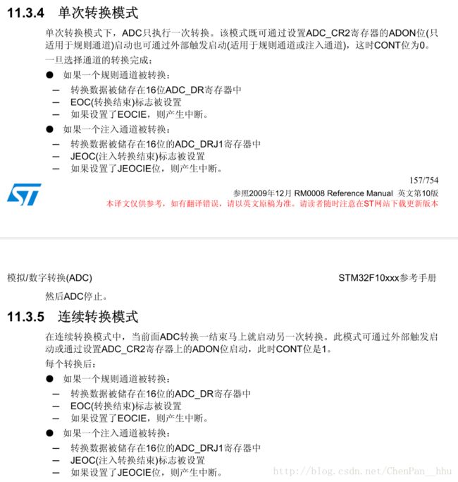
stm32 的转换模式有单次 连续等
ADC的时钟源是APB2,通过adcpre分频
adc的时钟不能超过14M,否则可能不准确,72M/6or8
extsel设为111 软件触发转换
转换时间 = 采样时间(smpr1/2设置)+12.5个周期
程序写法:
GPIO_Init();
APB2PeriphClockCmd();
② 复位ADC1,同时设置ADC1分频因子。(不需要)
RCC_ADCCLKConfig(RCC_PCLK2_Div6);
ADC_DeInit(ADC1);
③ 初始化ADC1参数,设置ADC1的工作模式以及规则序列的相关信息。
void ADC_Init(ADC_TypeDef*ADCx,ADC_InitTypeDef*ADC_InitStruct);
④ 使能ADC并校准。
ADC_Cmd(ADC1, ENABLE);
⑤配置规则通道参数:
ADC_RegularChannelConfig(ADC_TypeDef* ADCx,uint8_t ADC_Channel,uint8_t Rank, uint8_t ADC_SampleTime);
以上放到初始化函数中去
以下放到adc值读取函数中去
⑥开启软件转换:ADC_SoftwareStartConvCmd(ADC1);
⑦等待转换完成,读取ADC值。
ADC_GetConversionValue(ADC1);
具体 代码void adc_init()
{
GPIO_InitTypeDef GPIO_InitStructure;
ADC_InitTypeDef ADC_InitStructure;
/*①开启PB口时钟和ADC1时钟*/
GPIO_InitStructure.GPIO_Pin = GPIO_Pin_0;
GPIO_InitStructure.GPIO_Mode = GPIO_Mode_AIN;
GPIO_Init(GPIOB, &GPIO_InitStructure);
RCC_APB2PeriphClockCmd(RCC_APB2Periph_GPIOB | RCC_APB2Periph_ADC1, ENABLE);
/*②初始化ADC1参数,设置ADC1的工作模式以及规则序列的相关信息。*/
/* ADC1 configuration ------------------------------------------------------*/
ADC_InitStructure.ADC_Mode = ADC_Mode_Independent;//软件触发
ADC_InitStructure.ADC_ScanConvMode = DISABLE;//扫描的不要
ADC_InitStructure.ADC_ContinuousConvMode = DISABLE;//连续的不要
ADC_InitStructure.ADC_ExternalTrigConv = ADC_ExternalTrigConv_None;//外部触发的不要
ADC_InitStructure.ADC_DataAlign = ADC_DataAlign_Right;//不需要修改,默认为右
ADC_InitStructure.ADC_NbrOfChannel = 1;//一共就一个通道
ADC_Init(ADC1, &ADC_InitStructure);//初始化吧
/*配置规则通道参数:*/
/* ADC1 regular channels configuration */
ADC_RegularChannelConfig(ADC1, ADC_Channel_8, 1, ADC_SampleTime_28Cycles5);//adc1通道8 一个通道 其他按需/*使能ADC并校准。*//* Enable ADC1 */ ADC_Cmd(ADC1, ENABLE); /*校准按需*/ /* Enable ADC1 reset calibration register */ ADC_ResetCalibration(ADC1); /* Check the end of ADC1 reset calibration register */ while(ADC_GetResetCalibrationStatus(ADC1)); /* Start ADC1 calibration */ ADC_StartCalibration(ADC1); /* Check the end of ADC1 calibration */ while(ADC_GetCalibrationStatus(ADC1));}float ADC_getvalue(){
float ADC_VALUE
;
ADC_SoftwareStartConvCmd(ADC1,ENABLE);
while(ADC_GetFlagStatus(ADC1, ADC_FLAG_EOC) != SET);
ADC_VALUE = ADC_GetConversionValue(ADC1)*3.30/0xfff;//这三个函数从库里不好抄,需要从.h里识别出来
return ADC_VALUE;
}
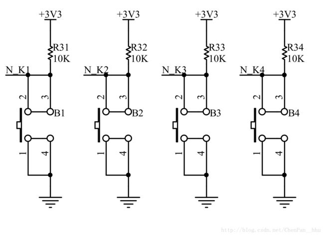
三、独立按键
个人习惯中断扫描,全局变量,手动清零
u8 key_value = 0;
void key_init(){
GPIO_InitTypeDef GPIO_InitStructure;
   RCC_APB2PeriphClockCmd(RCC_APB2Periph_GPIOA, ENABLE);
   RCC_APB2PeriphClockCmd(RCC_APB2Periph_GPIOB, ENABLE);


   GPIO_InitStructure.GPIO_Pin = GPIO_Pin_0|GPIO_Pin_8;
   GPIO_InitStructure.GPIO_Mode = GPIO_Mode_IPU;
//   GPIO_InitStructure.GPIO_Speed = GPIO_Speed_10MHz;
   GPIO_Init(GPIOA, &GPIO_InitStructure);
   GPIO_InitStructure.GPIO_Pin = GPIO_Pin_1|GPIO_Pin_2;
   GPIO_InitStructure.GPIO_Mode = GPIO_Mode_IPU;
//    GPIO_InitStructure.GPIO_Speed = GPIO_Speed_10MHz;
   GPIO_Init(GPIOB, &GPIO_InitStructure);
}
u8 key_read(){
	 if(GPIO_ReadInputDataBit(GPIOA,GPIO_Pin_0) == 0) return 1;
	 if(GPIO_ReadInputDataBit(GPIOA,GPIO_Pin_8) == 0) return 2;
	 if(GPIO_ReadInputDataBit(GPIOB,GPIO_Pin_1) == 0) return 3;
	 if(GPIO_ReadInputDataBit(GPIOB,GPIO_Pin_2) == 0) return 4;
	 return 0;
}
void key_scan(){//扫描周期10ms 中断内调用函数
	 static enum{
	 ready,check,pressed,release
	 }key_status = ready;
	 static u8 key_press_num;
	 u8 key_temp = key_read();
	 switch(key_status){
	 case ready:
	 	if(key_temp) key_status = check;
		break;
	case check:
		if(key_temp)  key_press_num++;
		else  key_press_num = 0;
		if(key_press_num == 2) key_status = pressed;
		break;
	case pressed:
		key_press_num = 0;
		key_value = key_temp;
		key_status = release;
		break;
	case release:
		if(!key_temp)	key_status = ready;
	}


}
四、定时器
SysTick_Config(SystemCoreClock/1000);//这是初始化,只有这一句,配置特方便,默认是1ms
/**这个函数在stm32f10x_it.c
  * @brief  This function handles SysTick Handler.
  * @param  None
  * @retval None
  */
void SysTick_Handler(void)
{
	if(TimingDelay) TimingDelay--;
	TimingCount++;
}
	while(1)
	{
		if(TimingCount % 100 == 58){

		}
		if(TimingCount % 10 == 0){

		}
	}


