Image inpainting 图像修复,基于梯度(一阶导数)和拉普拉斯算子(二阶导数)
Image inpainting
Bertalmio
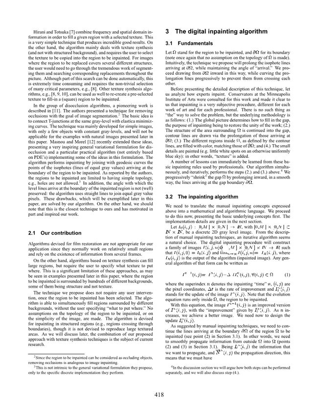
原文主要思想:沿待修复区域边缘从外向内修复,修复边缘和亮度,边缘垂直于一阶导,亮度变化速率用二阶导,代码半实现...因为虽然写出来但没有跑出效果。
每轮迭代15次再非线性各向异性散射2次,虽然我也不大懂,我搞出来的就像膨胀,是因为每次迭代我修改了边缘,但是如果边缘规整就不会膨胀。
一共两个文件:inpaint.m思想是用bfs找到以此被迭代的像素顺序,然后逐个执行迭代方程;anisodiff.m是非线性散射,参数是本人瞎填的别见怪。
inpaint.m
img = imread('img.png');
mask = imread('mask.png');

I = img .* uint8(mask == 0);

%初始化原图
nit = 1;
I = anisodiff(I, nit, 20, 0.1, 1);
I1 = I;

%用队列实现广度优先搜索,向内逐层迭代
%先分层
vis = zeros(size(mask));
q = zeros(50000, 2);
tail = 0;
for i = 1:200
    for j = 1:200
        if (mask(i,j) == 0)
            tail = tail+1;
            q(tail,:) = [i j];
            vis(i,j) = 1;
        end
    end
end
neighbour = [1 0; -1 0; 0 1; 0 -1];
head = 1;
while(head <= tail)
    for i = 1:4
        x = q(head,1);
        y = q(head,2);
        nx = x + neighbour(i,1);
        ny = y + neighbour(i,2);
        if (nx >= 1 && ny >= 1 && nx <=200 && ny <= 200 && vis(nx,ny) == 0)
            tail = tail+1;
            q(tail,:) = [nx ny];
            vis(nx,ny) = vis(x,y) + 1;
        end
    end
    head = head + 1;
end
%对每一层逐层执行inpainting
edgeValue = 2;
s = 1;
e = 1;
for i = 1:tail
    if ( vis(q(i,1), q(i,2)) == edgeValue)
        s = i;
        e = tail;
        for i = s:tail
            if (vis(q(i,1), q(i,2)) ~= edgeValue)
                e = i-1;
                break;
            end
        end
        edgeValue = edgeValue + 1;
        i = i-1;

        %inpainting主体
        A = 15;
        B = 2;
        detat = 0.1;
        for it = 1:A
            In = zeros(size(I));
            for j = s:e
                x = q(j,1);
                y = q(j,2);

                L = zeros(4);
                for d = 1:4
                    %(7)
                    nx = x+neighbour(d,1);
                    ny = y+neighbour(d,2);
                    Ixx = I(nx+1,ny) - 2*I(nx,ny) + I(nx-1,ny);
                    Iyy = I(nx,ny+1) - 2*I(nx,ny) + I(nx,ny-1);
                    L(d) = Ixx + Iyy;
                end

                %(6)
                sL = [L(1) - L(2), L(3) - L(4)];

                %(8)
                Ix = I(x+1,y) - I(x,y);
                Iy = I(x,y+1) - I(x,y);
                if (Ix == 0 && Iy == 0)
                    Norm = [0 , 0];
                else
                    Norm = [-Iy, -Ix] ./ ((Ix.^2 + Iy.^2).^0.5);
                end

                %(9)
                beta = dot(sL, Norm);

                %(10)
                if (beta >= 0)
                    Ixbm = min(0, I(x,y) - I(x-1,y));
                    IxfM = max(0, I(x+1,y) - I(x,y));
                    Iybm = min(0, I(x,y) - I(x,y-1));
                    IyfM = max(0, I(x,y+1) - I(x,y));
                    gI = (Ixbm.^2 + IxfM.^2 + Iybm.^2 + IyfM.^2).^0.5;
                else
                    IxbM = max(0, I(x,y) - I(x-1,y));
                    Ixfm = min(0, I(x+1,y) - I(x,y));
                    IybM = max(0, I(x,y) - I(x,y-1));
                    Iyfm = min(0, I(x,y+1) - I(x,y));
                    gI = (IxbM.^2 + Ixfm.^2 + IybM.^2 + Iyfm.^2).^0.5;
                end
                %(5)
                It = beta * gI;
                %(4)
                In(x,y) = I(x,y) + detat * It;
            end
            I = I + In;
        end
        %I = anisodiff(I, B, 15, 0.15, 1);
    end
end


%figure;imshow(I/255);
%figure;imagesc(I1);
%figure;imagesc(img);
%figure;imshow(img);
anisodiff.m
% ANISODIFF - Anisotropic diffusion.
%
% Usage:
%  diff = anisodiff(im, niter, kappa, lambda, option)
%
% Arguments:
%         im     - input image
%         niter  - number of iterations.
%         kappa  - conduction coefficient 20-100 ?
%         lambda - max value of .25 for stability
%         option - 1 Perona Malik diffusion equation No 1
%                  2 Perona Malik diffusion equation No 2
%
% Returns:
%         diff   - diffused image.
%
% kappa controls conduction as a function of gradient.  If kappa is low
% small intensity gradients are able to block conduction and hence diffusion
% across step edges.  A large value reduces the influence of intensity
% gradients on conduction.
%
% lambda controls speed of diffusion (you usually want it at a maximum of
% 0.25)
%
% Diffusion equation 1 favours high contrast edges over low contrast ones.
% Diffusion equation 2 favours wide regions over smaller ones.

% Reference:
% P. Perona and J. Malik.
% Scale-space and edge detection using ansotropic diffusion.
% IEEE Transactions on Pattern Analysis and Machine Intelligence,
% 12(7):629-639, July 1990.
%
% Peter Kovesi
% School of Computer Science & Software Engineering
% The University of Western Australia
% pk @ csse uwa edu au
% http://www.csse.uwa.edu.au
%
% June 2000  original version.
% March 2002 corrected diffusion eqn No 2.

function diff = anisodiff(im, niter, kappa, lambda, option)

if ndims(im)==3
  error('Anisodiff only operates on 2D grey-scale images');
end

im = double(im);
[rows,cols] = size(im);
diff = im;

for i = 1:niter
%  fprintf('\rIteration %d',i);

  % Construct diffl which is the same as diff but
  % has an extra padding of zeros around it.
  diffl = zeros(rows+2, cols+2);
  diffl(2:rows+1, 2:cols+1) = diff;

  % North, South, East and West differences
  deltaN = diffl(1:rows,2:cols+1)   - diff;
  deltaS = diffl(3:rows+2,2:cols+1) - diff;
  deltaE = diffl(2:rows+1,3:cols+2) - diff;
  deltaW = diffl(2:rows+1,1:cols)   - diff;

  % Conduction

  if option == 1
    cN = exp(-(deltaN/kappa).^2);
    cS = exp(-(deltaS/kappa).^2);
    cE = exp(-(deltaE/kappa).^2);
    cW = exp(-(deltaW/kappa).^2);
  elseif option == 2
    cN = 1./(1 + (deltaN/kappa).^2);
    cS = 1./(1 + (deltaS/kappa).^2);
    cE = 1./(1 + (deltaE/kappa).^2);
    cW = 1./(1 + (deltaW/kappa).^2);
  end

  diff = diff + lambda*(cN.*deltaN + cS.*deltaS + cE.*deltaE + cW.*deltaW);

%  Uncomment the following to see a progression of images
%  subplot(ceil(sqrt(niter)),ceil(sqrt(niter)), i)
%  imagesc(diff), colormap(gray), axis image

end
%fprintf('\n');
我只学习实现的这部分,抄写并翻译了第三章,一共有14页纸。
原文第三章:


