DA14580 启动过程分析
IC Booting
官方原话:
The DA1458x operates in two modes, namely the ‘Normal Mode’ and the ‘Development/Calibration Mode’ hereafter addressed as ‘DevMode’. The decision which mode the chip enters after power-up, is taken by the boot code residing in the ROM. A complete flow chart of the booting code is illustrated in the datasheet of the DA1458x.
DevMode will be entered when the OTP header contains a value zero at the first two addresses, when read by the CPU. This implies that the OTP is not programmed and the DA1458x should switch to the DevMode, so that users get access to download code from external devices into the internal SRAM (SysRAM). However, when the OTP contains specific values (magic numbers) in these locations the DA1458x will enter Normal Mode and proceed with mirroring of the OTP contents into the SysRAM in the booting sequence, as described in the datasheet.
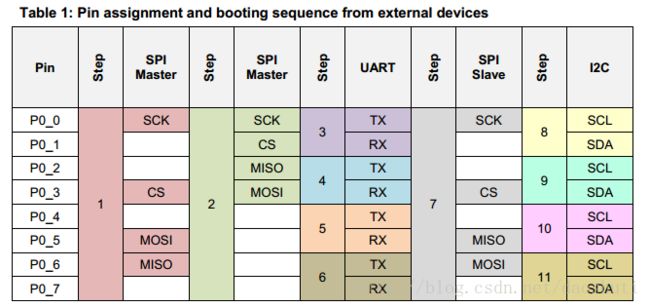
To allow for maximum flexibility, a predefined number of pins are examined and utilised at boot time to communicate with external devices using the three serial interfaces available on chip: UART, SPI and I2C. SPI and I2C can be masters on the DA1458x side expecting to communicate with an external slave device and SPI can also be slave expecting to communicate with an external master.
渣翻译:
DA1458x工作在两种模式下,即“Normal Mode”和“Development/Calibration Mode”,以下称为“DevMode”。上电之后芯片进入模式的决定由驻留在ROM中的引导代码取得。 DA1458x的数据表中给出了引导代码的完整流程图。
当OTP头在CPU的前两个地址中包含零值时,意味着OTP没有被编程,DA1458x将会切换到DevMode,以便用户可以访问从外部设备下载代码到内部SRAM(SysRAM)。但是,当OTP在这些位置包含特定值(magic numbers幻数)时,DA1458x将进入正常模式,并按照数据手册中的说明,在引导顺序中将OTP内容镜像到SysRAM中。
为了实现最大的灵活性,在引导时检查并使用预定义数量的引脚,以使用芯片上提供的三个串行接口(UART,SPI和I2C)与外部设备进行通信。 SPI和I2C可以作为DA1458x端的主设备,期望与外部从设备进行通信,SPI也可以作为从设备与外部主设备进行通信。
在启动过程中,端口P0用于检查是否存在外部设备。 下面的表1给出了引脚分配以及引导代码激活接口的顺序。
将OTP的代码装载到RAM
OTP 即 One Time Programmable (memory) 只能烧录一次。
如果对成本要求严格,可以将最终出货版本的代码烧录在OTP,这样就不用外挂Flash,可以有效降低成本。将OTP的代码装载到RAM后,启动流程也就到此为止了。
流程图如下:
如果需要进行OTA升级操作,则需要外挂Flash。这时需要将OTP内烧录为secondary_bootloader,进行二次引导,启动Flash中的代码。
从secondary_bootloader到Flash中的用户代码
secondary_bootloader的代码在\utilities\secondary_bootloader路径下,开发者可以根据自己的产品需求而定制自己的secondary_bootloader。
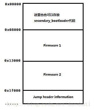
官方默认的secondary_bootloader是从Flash 0x1f000地址读取跳转的头信息。根据头信息,选择执行到Firmware1 的代码还是 Firmware2 的代码。
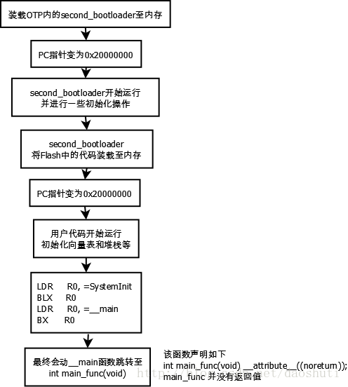
从secondary_bootloader到用户代码的启动流程如下:
关于arch_main函数的分析如下
我们先来看下main_func函数代码
int main_func(void)
{
    sleep_mode_t sleep_mode;

    //global initialise
    system_init();

    /*
     ************************************************************************************
     * Platform initialization
     ************************************************************************************
     */
    while(1)
    {
        do {
            // schedule all pending events
            schedule_while_ble_on();
        }
        while (app_asynch_proc() != GOTO_SLEEP);    //grant control to the application, try to go to power down
                                                              //if the application returns GOTO_SLEEP
              //((STREAMDATA_QUEUE)&& stream_queue_more_data())); //grant control to the streamer, try to go to power down
                                                                //if the application returns GOTO_SLEEP

        //wait for interrupt and go to sleep if this is allowed
        if (((!BLE_APP_PRESENT) && (check_gtl_state())) || (BLE_APP_PRESENT))
        {
          ...//省略
        }
    }
}
system_init();函数完成了系统的初始化操作。
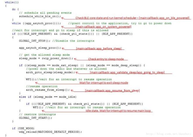
主循环由两部分组成。 第一部分在CPU处于活动状态时执行,只要内核或应用程序希望CPU保持活动状态。 在主循环的第二部分,程序试图进入掉电模式。 它将尝试关闭BLE硬件,然后关闭其余外设,并在等待来自某个外部引脚或BLE编程事件的中断(WFI)的同时将CPU置于低功耗状态。
系统初始化
system_init();函数完成了系统的初始化操作。
具体代码如下
/**
 ****************************************************************************************
 * @brief  Global System Init
 * @return void
 ****************************************************************************************
 */
void system_init(void)
{
    sys_startup_flag = true;
    /*
     ************************************************************************************
     * Platform initialization
     ************************************************************************************
     */
    //initialise the Watchdog unit
    wdg_init(0);

    //confirm XTAL 16 MHz calibration
    xtal16_calibration_check ();

    //set the system clocks
    set_system_clocks();

    //Initiliaze the GPIOs
    GPIO_init();

    // Initialize NVDS module
    nvds_init((uint8_t *)NVDS_FLASH_ADDRESS, NVDS_FLASH_SIZE);

    // Check and read BD address
    nvds_read_bdaddr();

    //Peripherals initilization
    periph_init();

    // Initialize random process
    srand(1);

    //Trim the radio from the otp
    iq_trim_from_otp();

    /*
     ************************************************************************************
     * BLE initialization
     ************************************************************************************
     */
    init_pwr_and_clk_ble();

    // Initialize BLE stack
    rwip_clear_interrupts ();

    // Initialize rw
    rwip_init(error);

    //Patch llm task
    patch_llm_task();

    //Patch gtl task
    if (BLE_GTL_PATCH)
        patch_gtl_task();

#if !defined( __DA14581__)
    //Patch llc task
    patch_llc_task();
#endif

#if !defined(__DA14581__)
    patch_atts_task();
#endif

#if (BLE_HOST_PRESENT)
    patch_gapc_task();
#endif

    //Enable the BLE core
    SetBits32(BLE_RWBTLECNTL_REG, RWBLE_EN, 1);

    // Initialise random number generator seed using random bits acquired from TRNG
    if (USE_TRNG)
        init_rand_seed_from_trng();

    //send a message to the host if an error occured
    if (BLE_HCIC_ITF)
        hcic_reset_message();

    rcx20_calibrate ();

    arch_disable_sleep();
    /*
     ************************************************************************************
     * Application initializations
     ************************************************************************************
     */
    // Initialise APP

#if (BLE_APP_PRESENT)
        app_init();         // Initialize APP
#endif

     if (user_app_main_loop_callbacks.app_on_init !=NULL)
          user_app_main_loop_callbacks.app_on_init();

    //Initialise lld_sleep
    lld_sleep_init_func();

    /*
     ************************************************************************************
     * XTAL16M trimming settings
     ************************************************************************************
     */
    //set trim and bias of xtal16
    xtal16__trim_init();

     // Enable the TX_EN/RX_EN interrupts, depending on the RF mode of operation (PLL-LUT and MGC_KMODALPHA combinations)
    enable_rf_diag_irq(RF_DIAG_IRQ_MODE_RXTX);

    /*
     ************************************************************************************
     * Watchdog
     ************************************************************************************
     */
    if(USE_WDOG)
    {
        wdg_reload(WATCHDOG_DEFAULT_PERIOD);
        wdg_resume ();
    }

#ifndef __DA14581__
# if (BLE_CONNECTION_MAX_USER > 4)
    cs_table[0] = cs_table[0];
# endif

#else //DA14581

# if (BLE_CONNECTION_MAX_USER > 1)
    cs_table[0] = cs_table[0];
# endif
#endif //__DA14581__

}
Main Loop
在SDK版本5.0.2(或更高版本)中,Main Loop被重写了。我们不应该随便主Main Loop,应将它认为是SDK的一部分。不过我们可以通过Main Loop 来理解应用程序的流程。

主循环由两部分组成。 第一部分在CPU处于活动状态时执行,只要内核或应用程序希望CPU保持活动状态。 在主循环的第二部分,程序试图进入掉电模式。 它将尝试关闭BLE硬件,然后关闭其余外设,并在等待来自某个外部引脚或BLE编程事件的中断(WFI)的同时将CPU置于低功耗状态。
Main Loop 的活动部分
通过rwip_schedule()函数让内核来进行调度控制。(注:rwip_schedule()在schedule_while_ble_on()函数中被调用。因为内核要运行的话,BLE硬件需处于活动状态。)
在schedule_while_ble_on()内,应用程序也通过user_app_main_loop_callbacks.app_on_ble_powered函数指针授予控制权。
根据app_on_ble_powered的返回值,应用程序可以强制主循环保持在schedule_while_ble_on()内,因为BLE保持活动状态。
如果应用程序和内核都允许scheduler_while_ble_on()返回,则将通过app_asynch_proc()函数和user_app_main_loop_callbacks.app_on_system_powered函数指针,再次获得控制权限,决定是否开始进入休眠。
app_on_system_powered的返回值与while循环类似。如果应用程序决定不做其他事情,软件将尝试进入休眠状态。


