1.路由器R1、R2在0区域,路由器R2、R3、R4在234区域,路由器R4、R5在45区域。
2.45区域没有与骨干区域直接相连,因此在不引入外部路由的情况下,需要在路由R2、R4上配置虚链路。
第一步,实验基本配置如下:R1
system-view
sysname R1
user-interface console 0
idle-timeout 1000
quit
interface GigabitEthernet0/0/2
ip address 192.168.1.254 255.255.255.0
interface GigabitEthernet0/0/1
ip address 192.168.17.1 255.255.255.0
interface GigabitEthernet0/0/0
ip address 192.168.12.1 255.255.255.0
quit
R2
system-view
sysname R2
interface GigabitEthernet0/0/1
ip address 192.168.12.2 255.255.255.0
interface GigabitEthernet0/0/0
ip address 192.168.23.2 255.255.255.0
quit
R3
system-view
sysname R3
interface GigabitEthernet0/0/1
ip address 192.168.23.3 255.255.255.0
interface GigabitEthernet0/0/0
ip address 192.168.34.3 255.255.255.0
quit
R4
system-view
sysname R4
interface GigabitEthernet0/0/1
ip address 192.168.34.4 255.255.255.0
interface GigabitEthernet0/0/0
ip address 192.168.45.4 255.255.255.0
quit
R5
system-view
sysname R5
interface GigabitEthernet0/0/1
ip address 192.168.45.5 255.255.255.0
interface GigabitEthernet0/0/2
ip address 192.168.5.254 255.255.255.0
interface GigabitEthernet0/0/0
ip address 100.1.1.5 255.255.255.0
quit
第二步,配置OSPF;配置命令如下:
R1
ospf 1 router-id 1.1.1.1
area 0
network 192.168.12.0 0.0.0.255
network 192.168.1.0 0.0.0.255
R2
ospf 1 router-id 2.2.2.2
area 0
network 192.168.12.0 0.0.0.255
area 234
network 192.168.23.0 0.0.0.255
R3
ospf 1 router-id 3.3.3.3
area 234
network 192.168.23.0 0.0.0.255
network 192.168.34.0 0.0.0.255
R4
ospf 1 router-id 4.4.4.4
area 234
network 192.168.34.0 0.0.0.255
area 45
network 192.168.45.0 0.0.0.255
R5
ospf 1 router-id 5.5.5.5
area 45
network 192.168.45.0 0.0.0.255
network 192.168.5.0 0.0.0.255
quit
查看R1的路由表,如下:[R1]display ip routing-table protocol ospf
Route Flags: R - relay, D - download to fib
Public routing table : OSPF
Destinations : 2 Routes : 2
OSPF routing table status :
Destinations : 2 Routes : 2
Destination/Mask Proto Pre Cost Flags NextHop Interface
192.168.23.0/24 OSPF 10 2 D 192.168.12.2 GigabitEthernet
0/0/0
192.168.34.0/24 OSPF 10 3 D 192.168.12.2 GigabitEthernet
0/0/0
 分析:由于45区域没有与骨干0区域直接相连,因此R1上面没有45区域的路由信息。

第三步,配置虚链路,即vlink-peer。
分别在R2、R4上配置vlink-peer:
R2
ospf 1
area 234
vlink-peer 4.4.4.4
R4
ospf 1
area 234
vlink-peer 2.2.2.2
验证:
    查看R1的路由表,如下:
[R1]display ip routing-table protocol ospf
Route Flags: R - relay, D - download to fib
Public routing table : OSPF
Destinations : 4 Routes : 4
OSPF routing table status :
Destinations : 4 Routes : 4
Destination/Mask Proto Pre Cost Flags NextHop Interface
192.168.5.0/24 OSPF 10 5 D 192.168.12.2 GigabitEthernet0/0/0
192.168.23.0/24 OSPF 10 2 D 192.168.12.2 GigabitEthernet
0/0/0
192.168.34.0/24 OSPF 10 3 D 192.168.12.2 GigabitEthernet
0/0/0
192.168.45.0/24 OSPF 10 4 D 192.168.12.2 GigabitEthernet
0/0/0
OSPF routing table status :
Destinations : 0 Routes : 0
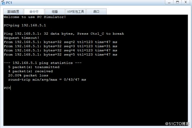
测试PC1、PC2的网络联通性:
总结
        查看R4的路由信息:
[R4]display ospf brief
 OSPF Process 1 with Router ID 4.4.4.4
     OSPF Protocol Information
RouterID: 4.4.4.4 Border Router: AREA
Multi-×××-Instance is not enabled
Global DS-TE Mode: Non-Standard IETF Mode
Graceful-restart capability: disabled
Helper support capability : not configured
Applications Supported: MPLS Traffic-Engineering
Spf-schedule-interval: max 10000ms, start 500ms, hold 1000ms
Default ASE parameters: Metric: 1 Tag: 1 Type: 2
Route Preference: 10
ASE Route Preference: 150
SPF Computation Count: 14
RFC 1583 Compatible
Retransmission limitation is disabled
Area Count: 3 Nssa Area Count: 0
ExChange/Loading Neighbors: 0
Process total up interface count: 3
Process valid up interface count: 2
 分析得出:
      R4路由状态以变为区域ABR,即虚链路使得R4直接与骨干区域相连。