上篇学了PorterDuffXfermode,本篇记录学习Shader
学习资料:
- Android群英传
- 爱哥写的非常非常好的系列:自定义控件其实很简单
本人很菜,哪里有错误,感谢指出
1.Shader 着色器
着色器就是用来上色的,可以用来实现一系列的渐变、渲染效果,有5个子类
-
BitmapShader位图Shader -
LinerGradient线性Shader -
RadialGradient光束Shader -
SweepGradient梯度Shader -
ComposeShader混合Shader
BitmapShader是唯一个可以用来给一个图片着色,其他四个就是渐变、渲染效果
2.BitmapShader 位图着色器
Shader used to draw a bitmap as a texture. The bitmap can be repeated or mirrored by setting the tiling mode.
将一个Bitmap作为纹理进行绘制,通过设置模式可以进行翻转或者镜像操作
只有一个构造方法
BitmapShader(@NonNull Bitmap bitmap, TileMode tileX, TileMode tileY)
构造方法中除了一个Bitmap外,还需要两个TileMode枚举类型的参数,一个代表在x轴的模式,一个在y轴的模式
2.1 TileMode 瓷砖模式
TileMode是Shader中的一个枚举,有三个值
-
CLAMP拉伸,图片的最后的一个像素,不断重复 -
REPEAT重复,横向、纵向不断重复 -
MIRROR镜像,横向不断翻转重复,纵向不断翻转重复
这里最常使用的就是CLAMP拉伸模式,虽然它会拉伸最后一个像素,但是只要将图像设置为一定的大小,就可以避免这种拉伸
利用CLMP得到一个圆形图片

private void init() {
    mPaint = new Paint(Paint.ANTI_ALIAS_FLAG);
    final Bitmap mBitmap = BitmapFactory.decodeResource(getResources(), R.drawable.test);
    final BitmapShader shader = new BitmapShader(mBitmap, Shader.TileMode.CLAMP, Shader.TileMode.CLAMP);
    mPaint.setShader(shader);
}

/**
 * 利用 clmp得到圆形图片
 */
@Override
protected void onDraw(Canvas canvas) {
    super.onDraw(canvas);
    float x = getWidth() / 2;
    float y = getHeight() / 2;
    float radius = Math.min(getWidth(), getHeight()) / 2;
    canvas.drawCircle(x, y, radius,mPaint);
}
布局文件中,大小设置的为200dp,这个时候可以正常显示,但设置为300dp时

这时图片的下面部分已经出现了问题,明显是最后一个元素被拉伸过多,使用这种方式得到圆形图片,拉伸后的图片要大于控件的大小,这样最后一个元素既然被拉伸变形,也看不到
2.2 BitmapShader下三种模式的效果
- REPEAT 重复
简单修改代码,将CLAMP变为REPEAT,图片资源变为R.mipmap.ic_launcher,画的图形由圆形变为矩形,布局中的宽度改为match_parent
 private void init() {
    mPaint = new Paint(Paint.ANTI_ALIAS_FLAG);
    final Bitmap mBitmap = BitmapFactory.decodeResource(getResources(), R.mipmap.ic_launcher);
    final BitmapShader shader = new BitmapShader(mBitmap, Shader.TileMode.REPEAT, Shader.TileMode.REPEAT);
    mPaint.setShader(shader);
}

@Override
protected void onDraw(Canvas canvas) {
    super.onDraw(canvas);

    canvas.drawRect(0,0,getWidth(),getHeight(),mPaint);
}

在整个View中,就会重复出现资源图片
- MIRROR 镜像

上下对称,出现镜像
上面的情况两个TileMode都是同一个值
- x轴CLAMP , y轴 MIRROR
final BitmapShader shader = new BitmapShader(mBitmap,Shader.TileMode.CLAMP, Shader.TileMode.MIRROR);

y轴是镜像,x轴最后的像素拉伸
- x轴 MIRROR, y轴 CLMP
final BitmapShader shader = new BitmapShader(mBitmap, Shader.TileMode.MIRROR,Shader.TileMode.CLAMP);
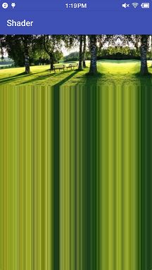
x轴镜像, y轴拉伸
BitmapShader总是先应用Y轴上的模式后,再应用X轴上的模式
x轴 MIRROR, y轴 CLMP,这种情况下,y轴先进行最后一个像素的拉伸后,再进行x轴的镜像,就出现了上面图片的效果
3. LinearGradient 线性渐变
构造方法,有两个
LinearGradient(float x0, float y0, float x1, float y1, int color0, int color1,TileMode tile)

LinearGradient(float x0, float y0, float x1, float y1, int colors[], float positions[],TileMode tile)
可以画出线性渐变
3.1第一种构造方法简单使用:
LinearGradient shader = new LinearGradient(0, 0, 600, 600, Color.RED, Color.YELLOW, Shader.TileMode.REPEAT);
mPaint.setShader(shader);
-
x0绘制x轴起始点 -
y0绘制y轴起始点 -
x1绘制x轴结束点 -
y1绘制y轴结束点 -
color0起始颜色 -
color1结束颜色 -
tile瓷砖模式
效果很容易理解,在控件中从0,0左上角点到600,600右下角两种颜色渐变
TileMode的效果和BitmapShader效果是一样的
但此时Shader.TileMode.REPEAT貌似没啥作用,这是由于控件的大小为600 * 600,渐变的结束点也是600 * 600,将渐变的结束点变成一半300 * 300
代码简单改动
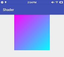
final LinearGradient shader = new LinearGradient(0, 0, 300, 300, Color.MAGENTA, Color.CYAN, Shader.TileMode.REPEAT);

这时,就出现了一个重复的渐变效果
3.2第二种构造方法
两个构造方法的区别在于,第4参数,是一个int[],第5个参数为一个float[],使用这个构造方法可以设置多种颜色的渐变
final int [] colors =  new int [] {Color.MAGENTA,Color.CYAN,Color.RED};
final float [] positions = new float[]{0f,0.50f,1f};
final LinearGradient shader = new LinearGradient(0, 0, 600, 600,colors ,positions ,Shader.TileMode.REPEAT);
-
colors颜色int值数组 -
postions数组中的值有效范围是0f~1f,渐变结束所在区域的比例,1f的结束位置,与x1,y1有关
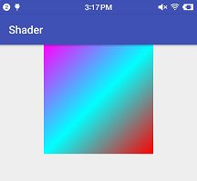
三种颜色,在起始点(0,0),二分之一点(300,300),结束点(600,600)的渐变效果
3.3 图片倒影效果
思路:
- 绘制原图,考虑绘制坐标,图片缩放
- 绘制倒影,利用
Matrix - 绘制渐变层,利用
PortDuffXfermode和LinearGradient

代码:
public class ReflectView extends View {
    private Paint mPaint;
    private Bitmap dstBitmap, srcBitmap;
    private PorterDuffXfermode xfermode;
    private int x, y;

    public ReflectView(Context context, AttributeSet attrs) {
        super(context, attrs);
        init();
    }

    private void init() {
        //原图Bitmap
        dstBitmap = decodeBitmapFormRes(getResources(), R.drawable.wa,540, 960);
        //垂直翻转
        Matrix matrix = new Matrix();
        matrix.setScale(1f, -1f);
        //倒影Bitmap
        srcBitmap = Bitmap.createBitmap(dstBitmap, 0, 0, dstBitmap.getWidth(), dstBitmap.getHeight(), matrix, true);
        //初始化画笔
        mPaint = new Paint(Paint.ANTI_ALIAS_FLAG);
        xfermode = new PorterDuffXfermode(PorterDuff.Mode.DST_IN);
         //屏幕宽度
        int screenW = getResources().getDisplayMetrics().widthPixels;
        //起始点
        x = screenW / 2 - dstBitmap.getWidth() / 2;
        y = 0;
        //设置渐变矩形
        mPaint.setShader(new LinearGradient(x, dstBitmap.getHeight(), x, dstBitmap.getHeight() + dstBitmap.getHeight() / 2, 0xDD000000, Color.TRANSPARENT, Shader.TileMode.CLAMP));
    }

    @Override
    protected void onDraw(Canvas canvas) {
        super.onDraw(canvas);
        //绘制背景
        canvas.drawColor(Color.BLACK);
        //绘制原图
        canvas.drawBitmap(dstBitmap, x, y, null);
        //绘制倒影图片
        canvas.drawBitmap(srcBitmap, x, dstBitmap.getHeight(), null);
        mPaint.setXfermode(xfermode);
        //绘制渐变层
        canvas.drawRect(x, dstBitmap.getHeight(), x + dstBitmap.getWidth(), dstBitmap.getHeight() * 2, mPaint);
        mPaint.setXfermode(null);
    }

    /**
     * 测量
     */
    @Override
    protected void onMeasure(int widthMeasureSpec, int heightMeasureSpec) {
        super.onMeasure(widthMeasureSpec, heightMeasureSpec);
        int wSpecMode = MeasureSpec.getMode(widthMeasureSpec);
        int wSpecSize = MeasureSpec.getSize(widthMeasureSpec);
        int hSpecMode = MeasureSpec.getMode(heightMeasureSpec);
        int hSpecSize = MeasureSpec.getSize(heightMeasureSpec);

        if (wSpecMode == MeasureSpec.AT_MOST && hSpecMode == MeasureSpec.AT_MOST) {
            setMeasuredDimension(300, 300);
        } else if (wSpecMode == MeasureSpec.AT_MOST) {
            setMeasuredDimension(300, hSpecSize);
        } else if (hSpecMode == MeasureSpec.AT_MOST) {
            setMeasuredDimension(wSpecSize, 300);
        }
    }

    /**
     * 图片的缩放
     */
    private Bitmap decodeBitmapFormRes(Resources resources, int resId, int targetWidth, int targetHeight) {
        final BitmapFactory.Options options = new BitmapFactory.Options();
        options.inPreferredConfig = Bitmap.Config.RGB_565;
        options.inJustDecodeBounds = false;
        BitmapFactory.decodeResource(resources, resId, options);
        int inSample = calculateInSample(options, targetWidth, targetHeight);
        options.inSampleSize = inSample;
        return BitmapFactory.decodeResource(resources, resId, options);
    }

    private int calculateInSample(BitmapFactory.Options options, int targetWidth, int targetHeight) {
        if (targetWidth <= 0 || targetHeight <= 0) {
            return 1;
        }
        int inSample = 1;
        final int rawWidth = options.outWidth;
        final int rawHeight = options.outHeight;
        if (rawWidth > targetWidth || rawHeight > targetHeight) {
            final int halfWidth = rawWidth / 2;
            final int halfHeight = rawHeight / 2;
            while ((halfWidth / inSample >= targetWidth) && (halfHeight / inSample >= targetHeight)) {
                inSample *= 2;
            }
        }
        return inSample;
    }
}
关于Matrix下下篇可能会学习 : )
4.RadialGradient 光束渐变
同样有两个构造方法
RadialGradient(float centerX, float centerY, float radius,  int centerColor, int edgeColor, @NonNull TileMode tileMode)

RadialGradient(float centerX, float centerY, float radius, @NonNull int colors[], @Nullable float stops[], @NonNull TileMode tileMode)
用法同LinearGradient类似
第一种构造方法简单使用:
final RadialGradient shader = new RadialGradient(300f,300f,300,Color.RED,Color.YELLOW, Shader.TileMode.CLAMP);
-
centerX渐变中心点的X轴坐标 -
centerY渐变中心点的Y轴坐标 -
radius渐变区域的半径
控件大小为600 * 600,(300f,300f)为控件的中心,半径为300
第二种构造方法简单使用:
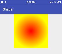
final int[] colors = new int[]{Color.YELLOW,Color.BLUE ,Color.RED};
final float[] positions = new float[]{0f, 0.5f ,1f};
final RadialGradient shader = new RadialGradient(300f,300f,300,colors,positions, Shader.TileMode.CLAMP);

colors中的元素个数要和positions中的元素个数相等
5. SweepGradient 梯度渐变
也有两个构造方法
SweepGradient(float cx, float cy, int color0, int color1)

SweepGradient(float cx, float cy, int colors[], float positions[])
cx,cy是旋转点的x,y轴坐标,渐变过程总是顺时针方向旋转
第一种构造方法简单使用:
final SweepGradient shader = new SweepGradient(300f,300f,Color.RED,Color.YELLOW);
        mPaint.setShader(shader);

控件的大小为600 * 600,300f * 300f就是整个控件的中心,可以试试其他的值
第二种构造方法简单使用:

final int[] colors = new int[]{Color.MAGENTA, Color.CYAN,Color.YELLOW,Color.BLUE ,Color.RED};
final float[] positions = new float[]{0f, 0.25f,0.5f ,0.75f,1f};
final SweepGradient shader = new SweepGradient(300f, 300f, colors, positions);
这里的positons中的值是固定的,o.25f的位置就是画的竖线的位置,其他的值类推
6. ComposeShader 混合渐变
也是有两个构造方法,但和之前的形式不再类似
ComposeShader(Shader shaderA, Shader shaderB, PorterDuff.Mode mode)

ComposeShader(Shader shaderA, Shader shaderB, Xfermode mode)
构造方法中,前两个参数相同,都是需要一个着色器,差别在于第三个参数。第一个构造方法需要一个PorterDuff.Mode,而第二个构造构造方法需要PorterDuffXfermode
前面的三种的渐变,都是一种单一的渐变,ComposeShader可以把前面两种渐变混合进一种渐变效果
简单使用:
private void init() {
    setLayerType(View.LAYER_TYPE_SOFTWARE, null);//关闭硬件加速
    mPaint = new Paint(Paint.ANTI_ALIAS_FLAG);
    final LinearGradient linearGradient = new LinearGradient(0, 0, 600, 600,Color.GREEN ,Color.BLUE ,Shader.TileMode.CLAMP);
    final RadialGradient radialGradient = new RadialGradient(300f,300f,300,Color.RED,Color.YELLOW, Shader.TileMode.CLAMP);

    final ComposeShader shader = new ComposeShader(linearGradient, radialGradient, PorterDuff.Mode.SCREEN);
    mPaint.setShader(shader);
}

在系统5.1.1的坚果手机上,必须要把硬件加速关闭,ComposeShader混合渐变效果才会出现,否则屏幕一片空白,手边暂时没有了别的手机,不知道会不会也是这样
第3个参数,new PorterDuffXfermode(PorterDuff.Mode.SCREEN)和PorterDuff.Mode.SCREEN这两种写法有啥区别,暂时也没看出来
7.最后
Paint的基础知识学习先到这里了。下篇记录学习Canvas中的方法及属性
一直写到现在,脑袋有点混了,休息
突然感觉写的基础知识都没记住,回头再看看
周末愉快,共勉 : )