个人项目分享——odroid + arduino 机器视觉小车制作
这是一个之前在学校参加学院组织的一个利用图像处理来使小车跑起来的一个项目。实现的内容有点类似飞思卡尔的摄像头组,但是区别在于飞思卡尔的为纯单片机的硬件实现,而这里是使用的类似树莓派的一个卡片电脑odroid进行图像处理,然后与arduino进行串口通信,用arduino实现舵机、电机驱动。
话不多说,先上视频:演示视频1 演示视频2 演示视频3
这个是调试过程的视频:调试视频(围着好多女生有点紧张)
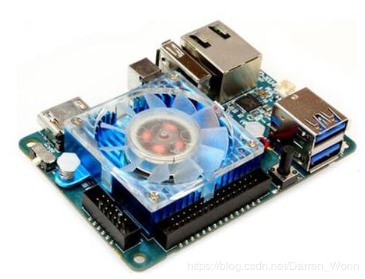
说下本项目用到的硬件:①odroid②arduino③罗技摄像头④带舵机带电调的越野小车


知识:OpenCV Linux指令 arduino代码编程 pwm脉宽调制原理 电调驱动原理 舵机驱动原理 图像处理常用方式 C++
好,开始项目内容
首先是要使用odroid,在odroid中安装好Linux系统(这里使用的是Ubuntu mate16.04)。然后就是配置一系列的环境了(OpenCV gcc编译器 minicom等等)。其中个人感觉OpenCV的环境配置对新手来说是有点难度的,但是配置成功一次后,下次你再配置就觉得很简单了,这里介绍一些环境配置时我看到过觉得有用和问题解决的博客:
OpenCV安装 配置c/c++ Ubuntu18.04下安装OpenCv依赖包libjasper-dev无法安装的问题
配置好odroid的开发环境后,就可以开始搭建硬件了,硬件连接图如下所示:

搭建好车子:

图像处理过程:采集图像、平滑滤波、RGB转换、二值化、降噪算法、路径规划
电机舵机控制方案:舵机PD控制、电机PID控制
下面附下参考代码(仅供参考,不喜勿喷嘻嘻):
arduino比较重要的部分代码(不完整,因为不是自己写的),主要是通过接受odroid发送过来的指令进行舵机的转向调制以及电机的速度设定:
#include
#define POWER 0
#define STEERING 1
//************** MODE AND CONTROL VARS *****************//
char use_control_system = 0;
char mode = 0;

//************** CONTROL SYSTEM VARS ******************//
float speedInput = 0.0;     // meters/s
float kd = 100.0;
float kp = 20.0;
float ki = 0.0;
char useControlSystem = 0;
float prevError = 0;
#define TIRE_CIRCUMFERENCE 0.3 // meters
#define ENCODER_PULSES_PER_TIRE_REV 814 // This if for one revolution of the tire
#define PULSES_PER_METER 2713 // ENCODER_PULSES_PER_TIRE_REV/TIRE_CIRCUMFERENCE


//******************* SERIAL OBJECTS ******************//
String  inString = "";    // string to hold input
String  command = "";
String  valueString = "";
int commandStarted = 0;
float     value = 0;
#define     BAUD_RATE 115200

//******************* SERVO OBJECTS ******************//
Servo steeringServo;
Servo powerServo;
int POWER_PIN = 5; //5;
int STEERING_PIN = 9; //9;
int PULSES = 1500; // Hard Right - 2000. Hard Left - 1000. Middle - 1500.
int PULSEP = 1450; // Fast Forward - 2000. Fast Reverse - 1000. Stopped - 1500.

//******************* ENCODER OBJECTS ******************//
// These *need* to be pins 2 and 3, those are the only pins on nano that allow
// for external interrupts to be mounted.
//这些*需要*为引脚2和3,这些是nano上允许的唯一引脚
//用于挂载外部中断。
#define encoder0PinA 2
#define encoder0PinB 3
#define updateEncoderPeriod 100 // value in ms
volatile signed long encoder0Pos = 0;
float encoderChange = 0;
signed long encoderLast = 0;
unsigned long startTime = 0;
unsigned long endTime = 0;

void setup()
{
  pinMode(STEERING_PIN, OUTPUT);
  pinMode(POWER_PIN, OUTPUT);
  Serial.begin(BAUD_RATE);     // opens serial port, sets baud rate打开串口,设置波特率
  steeringServo.attach(STEERING_PIN);
  steeringServo.writeMicroseconds(PULSES);

  powerServo.attach(POWER_PIN);
  powerServo.writeMicroseconds(PULSEP);
  pinMode(encoder0PinA, INPUT);
  pinMode(encoder0PinB, INPUT);
  attachInterrupt(0, doEncoderA, RISING);

  startTime = millis();
  endTime = startTime+updateEncoderPeriod;

}

int checkForSerial(){
  //Function that checks if serial is available and parses commands
//检查串行是否可用并解析命令的函数
  if (Serial.available() > 0) {
      int inChar = Serial.read();
      if(inChar == '!'){
        commandStarted = 1;
        valueString = "";
        command = "";
      }

      if(commandStarted == 0){
        return 0;
      }
      if (isDigit(inChar) || inChar == '.') {
        valueString += (char)inChar;
      }if(isAlpha(inChar)){
        command += (char)inChar;
      }
      // if you get a newline, the command is complete.
      // update values if logical and send response.
//如果你得到一个换行符,这个命令就完成了。
       / /如果逻辑和发送响应更新值。

      if (inChar == '\n') {
        commandStarted = 0;

        value = valueString.toFloat();


        if(command=="p"){
          if(useControlSystem==0){
            if(value >=1000){
              if(value <= 2000){
                PULSEP = value;
                powerServo.writeMicroseconds(PULSEP);
                Serial.print("Power: ");
                Serial.println(PULSEP);
              }
            }
          }else{
            Serial.println("Cannot set power value directly when using control system.");
          }
        }else if(command=="s"){
          PULSES = value;
          steeringServo.writeMicroseconds(PULSES);
          Serial.print("Steering: ");
          Serial.println(PULSES);

        }else if(command=="enc"){
          readEncoder();
        }
        else if(command=="usecs"){
          if(value==1){
            useControlSystem = 1;
            Serial.println("Using control system");
          }else if(value==0){
            useControlSystem = 0;
            Serial.println("Not using control system");
          }else{
            Serial.println("Value not acceptable for command: usecs");
          }
        }else if(command=="speedf"){
            if(value < 5){
              speedInput = value;
              //speedInput = speedInput/10.0;
              Serial.print("Forward Speed: ");
              Serial.println(value);
            }else{
              Serial.println("Value too high for command: speedf");
            }

        }else if(command=="speedr"){
            if(value < 5){
              speedInput = -value;
              //speedInput = speedInput/10.0;
              Serial.print("Reverse Speed: ");
              Serial.println(value);
            }else{
              Serial.println("Value too high for command: speedr");
            }

        }else{

          Serial.print("Command: (");
          Serial.print(command);
          Serial.println(") not recognized");
        }

        // clear the string for new input:
//清除新输入的字符串:
        valueString = "";
        command = "";
      }
    }
    return 0;
}
}
odroid的串口通信部分配置代码:
nt setupSerial(){

    struct termios toptions;

    /* open serial port */
    fd = open("/dev/ttyUSB0", O_RDWR | O_NOCTTY);
    printf("fd opened as %i\n", fd);

    /* wait for the Arduino to reboot */
    usleep(1500000);


    /* get current serial port settings */
    tcgetattr(fd, &toptions);
    /* set 115200 baud both ways */
    cfsetispeed(&toptions, B115200);
    cfsetospeed(&toptions, B115200);
    /* 8 bits, no parity, no stop bits */
    toptions.c_cflag &= ~PARENB;
    toptions.c_cflag &= ~CSTOPB;
    toptions.c_cflag &= ~CSIZE;
    toptions.c_cflag |= CS8;
    /* Canonical mode */
    toptions.c_lflag |= ICANON;
    /* commit the serial port settings */
    tcsetattr(fd, TCSANOW, &toptions);
    printf("Attempting to communicate with arduino... \n");

    return 0;
}
指令传输部分代码:
void sendCommand(const char* command){
    printf("Sending Command: %s", command);
    /* Send byte to trigger Arduino to send string back */
    //printf("Command size: %d\n", size);


    write(fd, command, strlen(command));
    //Receive string from Arduino
    n = read(fd, buf, 64);
    //insert terminating zero in the string
    buf[n] = 0;

    printf("Command Returned: %s\n", buf);

}
舵机转向指令代码:
void setTurnValue(int value){
	if(value==lastTurnValueSent){
		return;
	}
	lastTurnValueSent = value;
	std::string stringValue = std::to_string(1500+value*16);
	std::string command = "!s" + stringValue + "\n";
	const char * c = command.c_str();
	printf("turn: %d °\n", value);
	sendCommand(c);
}
图像处理的代码(获取图像、颜色空间转换、二值化、危险判断)
void processFrames(){
    // capture loop
    char key = 0;

    while(key != 'q')
    {
        if(pointer==&tempImage1){
            myMutex1.lock();
            image = *pointer;
            mutexToUnlock  = 1;
        }else if(pointer == &tempImage2){
            myMutex2.lock();
            image = *pointer;
            mutexToUnlock  = 2;

        }

        if(!image.empty()){
            //添加图像处理加小车控制代码
			vector channels;//定义矢量channels
			Mat drcimg;
			cvtColor(image,drcimg,CV_RGB2HLS);//cvCvtColor 将输入图像从一个色彩空间转换为另外一个色彩空间
			split(drcimg,channels);//通道分离函数:split(srcImage,channels)

			image=channels.at(2); //channels.at(0) / channels.at(1) / channels.at(2)为对channels的引用
			threshold(image,drcimg,70,255,0);//二值化
			ad=0;
			sum1=sum2=bigest=t=g=f=0;

			//图像栅格化
			for(int i=0;i<20;i++)
				for(int j=0;j<20;j++)
				{
					for(int h=24*i;h>=24*i&&h<24*(i+1);h++)
					{
						uchar* data = drcimg.ptr(h); /*图像第h行的头指针,通过这个指针结合列的位置(就是代码中的w)可以很轻松操作图像改行的每一列。
                                                           需要通过它来指定当前mat中图像的数据类型,这样才能跟外面定义的uchar* data吻合,这样才能正确的访问数据 */
						for(int w=32*j;w>=32*j&&w<32*(j+1);w++)
						{
							ad+=data[w];
						}
					}
					b[i][j]=ad;
					ad=0;
				}
			//找出一列的危险距离
			for (int j=0;j<20;j++)
				for (int i=19;i>=0;i--)
				{
					if(b[i][j]!=0&&i!=0)
					{
						if (b[i-1][j]!=0)
						{
							c[j]=20-i;
							break;
						}
					}
					else
						c[j]=20;
				}
			//计算最优值
				bigest=c[0];
				for (int i=0;i<20;i++)
					if(c[i]>bigest)
						bigest=c[i];
				for (int i=0;i<10;i++)
					sum1+=c[i];
				for (int i=10;i<20;i++)
					sum2+=c[i];
				if(sum1==sum2)
					f=20;
				else if (sum1>sum2)
				{
					for (int i=0;i<10;i++)
					{
						if (c[i]==bigest)
						{
							t++;
							g+=i+1;
						}
					}
					if(t!=0)
						f=(int)g/t;
				}
				else if (sum1