下面的内容均在imx6平台上举例,这一次分析希望将整个GPIO子系统的所有细节整理清晰。
第一篇从gpiolib入手,后面的边分析边写.
开始之前给自己提几个问题
- 驱动开发中的GPIO API 究竟是怎么实现的?
- GPIO的中断又是怎么实现的?
- GPIO号和IRQ的号码怎么映射的?
1.芯片定义
我们在驱动程序中会用到gpio_request(x),这里的x便是gpio的编号,而GPIO通常会分组,在原理图经常会看见GPIO2_5类似的标识,通常我们先会翻阅一下datesheet来了解一下这块芯片的定义是如何。
在imx6芯片中的将GPIO分成了若干组,每组为32个管脚。
我们简单的阅读一下芯片手册:
IMX6的gpio控制结构:
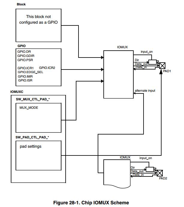
我们的芯片会引出一堆引脚,而在芯片的内部会集成很多control,(我们称这些control为block)其中的引脚可以功能复用,比如说A1 A2脚支持I2C功能也支持GPIO功能,我可以将I2C1_control的管脚连接过来,或者将GPIO1_1的管脚连接上来,这个就是IOMUX的作用:提供PIN不同的功能切换。
所以我们在使用芯片之前会先根据主板的配置先将各个管脚配置为正确的功能的Pin.
寄存器:
- Data register (GPIO_DR)
- GPIO direction register (GPIO_GDIR)
- Pad sample register (GPIO_PSR)
- Interrupt control registers (GPIO_ICR1, GPIO_ICR2)
- Interrupt mask register (GPIO_IMR)
- Interrupt status register (GPIO_ISR)
- GPIO edge select register (GPIO_EDEG_SEL )
简单介绍一下
- DR 当作为输出时控制管脚高低电平
- GDIR 控制管脚作为输入还是输出
- PSR 作为输出时获取管脚的高低电平
- ICR1 ICR2 是配置中断的触发方式 高/低电平触发 上升/下降沿 触发
- IMR 中断屏蔽寄存器
- ISR 中断状态寄存器 哪个管脚触发了中断
- EDEG_SEL 边缘触发模式(上/下沿都触发)
GPIO有7组,每组32个,最后一组14个
2.设备树
我们了解了一下内部的结构,接着就要开始看代码了,在看代码之前看看设备树,才能定位到代码在哪里。
这里只列出一个gpio-controller
 aliases {
                ethernet0 = &fec;
                can0 = &can1;
                can1 = &can2;
                gpio0 = &gpio1;
                gpio1 = &gpio2;
                .....
 }
gpio1: gpio@0209c000 {
                            compatible = "fsl,imx6q-gpio", "fsl,imx35-gpio";
                            reg = <0x0209c000 0x4000>;
                            interrupts = <0 66 IRQ_TYPE_LEVEL_HIGH>,
                                         <0 67 IRQ_TYPE_LEVEL_HIGH>;
                            gpio-controller;
                            #gpio-cells = <2>;
                            interrupt-controller;
                            #interrupt-cells = <2>;
                    };
我们通过compatible的值可以找到对应的驱动代码路径 driver/gpio/gpio-mxc.c
GPIO1控制寄存器的地址是0x0209c000,长度0x4000,使用66和67号中断。
这里疑惑的地方是为什只用了两个中断号,而不是32个?
我们知道一个GPIO控制是通过总线连接到CPU,中断连接到中断控制器(GIC),那么中断线太多就以为着GIC的数量也需要增加,如果GPIO控制器内部进行判断是哪个管脚触发的那么就可以避免GIC的数量。
而我们的芯片内部只有一个GIC.
| IRQ | Source | Interrupt Description |
|---|---|---|
| 32 | IOMUXC | General Purpose Register 1 from IOMUXC. Used to notify cores on exception condition whileboot. |
| 33 | DAP | Debug Access Port interrupt request |
| 98 | GPIO1 | Combined interrupt indication for GPIO1 signals 0 - 15. |
| 99 | GPIO1 | Combined interrupt indication for GPIO1 signals 16 - 31. |
这里中断号的来源是芯片手册,因为GIC的连接是这样的,这里0-31是内部使用,32开始用作外设。
驱动中用编号0直接开始编号。
地址参考寄存器MAP
| Absolute | address | Register name Widt (bits) | Access | Reset value |
|---|---|---|---|---|
| 209_C000 | GPIO data register (GPIO1_DR) | 32 | R/W | 0000_0000h |
| 209_C004 | GPIO direction register (GPIO1_GDIR) | 32 | R/W | 0000_0000h |
| 209_C008 | GPIO pad status register (GPIO1_PSR) | 32 | R | 0000_0000h |
| 209_C00C | GPIO interrupt configuration register1 (GPIO1_ICR1) | 32 | R/W | 0000_0000h |
| 209_C010 | GPIO interrupt configuration register2 (GPIO1_ICR2) | 32 | R/W | 0000_0000h |
| 209_C014 | GPIO interrupt mask register (GPIO1_IMR) | 32 | R/W | 0000_0000h |
| 209_C018 | GPIO interrupt status register (GPIO1_ISR) | 32 | w1c | 0000_0000h |
| 209_C018 | GPIO interrupt status register (GPIO1_ISR) | 32 | w1c | 0000_0000h |
| 209_C01C | GPIO edge select register (GPIO1_EDGE_SEL) | 32 | R/W | 0000_0000h |
| 20A_0000 | GPIO data register (GPIO2_DR) | 32 | R/W | 0000_0000h |
3.代码
从设备树中我们知道了代码的路径位置,我们先看看gpio这个目录的Makefile:
obj-$(CONFIG_GPIO_DEVRES)       += devres.o
obj-$(CONFIG_GPIOLIB)           += gpiolib.o
obj-$(CONFIG_GPIOLIB)           += gpiolib-legacy.o
obj-$(CONFIG_OF_GPIO)           += gpiolib-of.o
obj-$(CONFIG_GPIO_SYSFS)        += gpiolib-sysfs.o
obj-$(CONFIG_GPIO_ACPI)         += gpiolib-acpi.o

# Device drivers. Generally keep list sorted alphabetically
obj-$(CONFIG_GPIO_GENERIC)      += gpio-generic.o

obj-$(CONFIG_GPIO_74X164)       += gpio-74x164.o
.....(省略一些无关紧要的内容)
obj-$(CONFIG_GPIO_MXC)          += gpio-mxc.o
这里分三类:
- gpiolib的代码
- gpio-generic代码
- gpio特定平台的代码
代码的结构:
GPIOLIB 调用 GPIO_GENRIC 调用 GPIO_MXC
接着我们开始分析代码:
代码主要讲了初始化GPIO控制器和GPIO的中断控制器,这里先分析gpio控制器和如何与gpiolib联系
static const struct of_device_id mxc_gpio_dt_ids[] = {
        { .compatible = "fsl,imx1-gpio", .data = &mxc_gpio_devtype[IMX1_GPIO], },
        { .compatible = "fsl,imx21-gpio", .data = &mxc_gpio_devtype[IMX21_GPIO], },
        { .compatible = "fsl,imx31-gpio", .data = &mxc_gpio_devtype[IMX31_GPIO], },
        { .compatible = "fsl,imx35-gpio", .data = &mxc_gpio_devtype[IMX35_GPIO], },
        { /* sentinel */ }
};
enum mxc_gpio_hwtype {
        IMX1_GPIO,      /* runs on i.mx1 */
        IMX21_GPIO,     /* runs on i.mx21 and i.mx27 */
        IMX31_GPIO,     /* runs on i.mx31 */
        IMX35_GPIO,     /* runs on all other i.mx */
};


static struct platform_device_id mxc_gpio_devtype[] = {
        {
                .name = "imx1-gpio",
                .driver_data = IMX1_GPIO,
        }, {
                .name = "imx21-gpio",
                .driver_data = IMX21_GPIO,
        }, {
                .name = "imx31-gpio",
                .driver_data = IMX31_GPIO,
        }, {
                .name = "imx35-gpio",
                .driver_data = IMX35_GPIO,
        }, {
                /* sentinel */
        }
};
这里是为了兼容性考虑,这个分支感觉写的很有水准以后可以借鉴一下。
接着来看看porbe 的流程
static int mxc_gpio_probe(struct platform_device *pdev)
{
    struct device_node *np = pdev->dev.of_node;
    struct mxc_gpio_port *port;
    struct resource *iores;
    int irq_base;
    int err;

    mxc_gpio_get_hw(pdev); //1

    port = devm_kzalloc(&pdev->dev, sizeof(*port), GFP_KERNEL);
    if (!port)
        return -ENOMEM;

    //从设备树中获取寄存器地址,IOREMAP就是将物理地址转化称虚拟地址
    iores = platform_get_resource(pdev, IORESOURCE_MEM, 0);
    port->base = devm_ioremap_resource(&pdev->dev, iores);
    if (IS_ERR(port->base))
        return PTR_ERR(port->base);
    //从设备树中获取中断号,上面也解释了为啥是2个。
    port->irq_high = platform_get_irq(pdev, 1);
    port->irq = platform_get_irq(pdev, 0);
    if (port->irq < 0)
        return port->irq;

    //关中断,清理中断触发状态。
    //中断屏蔽位的作用就是是否要关心这个中断
    //中断状态位的作用就是,当中断发生了,我们需要查一下是谁发生了中断。
    /* disable the interrupt and clear the status */
    writel(0, port->base + GPIO_IMR);
    writel(~0, port->base + GPIO_ISR);

    if (mxc_gpio_hwtype == IMX21_GPIO) {
        /*
         * Setup one handler for all GPIO interrupts. Actually setting
         * the handler is needed only once, but doing it for every port
         * is more robust and easier.
         */
        irq_set_chained_handler(port->irq, mx2_gpio_irq_handler);
    } else {
        /* setup one handler for each entry */
        //2
        //函数修改父中断的流控函数,当发生中断,中断控制器会去调用这个函数
        irq_set_chained_handler(port->irq, mx3_gpio_irq_handler);
        irq_set_handler_data(port->irq, port);
        if (port->irq_high > 0) {
            /* setup handler for GPIO 16 to 31 */
            irq_set_chained_handler(port->irq_high,
                        mx3_gpio_irq_handler);
            irq_set_handler_data(port->irq_high, port);
        }
    }

    //3
    err = bgpio_init(&port->bgc, &pdev->dev, 4,
             port->base + GPIO_PSR,
             port->base + GPIO_DR, NULL,
             port->base + GPIO_GDIR, NULL, 0);
    if (err)
        goto out_bgio;
//设置gpio和软件中断号映射的关系
    port->bgc.gc.to_irq = mxc_gpio_to_irq;
//设置gpio的编号基数
    port->bgc.gc.base = (pdev->id < 0) ? of_alias_get_id(np, "gpio") * 32 :
                         pdev->id * 32;
//将GPIO控制器计入到gpiolib驱动的链表中,也就是之后我们可以gpio_direction去操作io了
    err = gpiochip_add(&port->bgc.gc);
    if (err)
        goto out_bgpio_remove;

    irq_base = irq_alloc_descs(-1, 0, 32, numa_node_id());
    if (irq_base < 0) {
        err = irq_base;
        goto out_gpiochip_remove;
    }
//向中断控制器注册并创建映射关系
    port->domain = irq_domain_add_legacy(np, 32, irq_base, 0,
                         &irq_domain_simple_ops, NULL);
    if (!port->domain) {
        err = -ENODEV;
        goto out_irqdesc_free;
    }
//初始化gpio中断控制器
    /* gpio-mxc can be a generic irq chip */
    mxc_gpio_init_gc(port, irq_base);

    list_add_tail(&port->node, &mxc_gpio_ports);

    return 0;

out_irqdesc_free:
    irq_free_descs(irq_base, 32);
out_gpiochip_remove:
    gpiochip_remove(&port->bgc.gc);
out_bgpio_remove:
    bgpio_remove(&port->bgc);
out_bgio:
    dev_info(&pdev->dev, "%s failed with errno %d\n", __func__, err);
    return err;
}
先看 mxc_gpio_get_hw吧,其实也就是初始化了两个全局变量:
static enum mxc_gpio_hwtype mxc_gpio_hwtype;
static struct mxc_gpio_hwdata *mxc_gpio_hwdata;

static void mxc_gpio_get_hw(struct platform_device *pdev)
{
    const struct of_device_id *of_id =
            of_match_device(mxc_gpio_dt_ids, &pdev->dev);
    enum mxc_gpio_hwtype hwtype;

    if (of_id)
        pdev->id_entry = of_id->data;
    hwtype = pdev->id_entry->driver_data;

    if (mxc_gpio_hwtype) {
        /*
         * The driver works with a reasonable presupposition,
         * that is all gpio ports must be the same type when
         * running on one soc.
         */
        BUG_ON(mxc_gpio_hwtype != hwtype);
        return;
    }

    if (hwtype == IMX35_GPIO)
        mxc_gpio_hwdata = &imx35_gpio_hwdata;
    else if (hwtype == IMX31_GPIO)
        mxc_gpio_hwdata = &imx31_gpio_hwdata;
    else
        mxc_gpio_hwdata = &imx1_imx21_gpio_hwdata;

    mxc_gpio_hwtype = hwtype;
}
看一眼这两个变量是何方神圣:
enum mxc_gpio_hwtype {
        IMX1_GPIO,      /* runs on i.mx1 */
        IMX21_GPIO,     /* runs on i.mx21 and i.mx27 */
        IMX31_GPIO,     /* runs on i.mx31 */
        IMX35_GPIO,     /* runs on all other i.mx */
};

struct mxc_gpio_hwdata {
        unsigned dr_reg;
        unsigned gdir_reg;
        unsigned psr_reg;
        unsigned icr1_reg;
        unsigned icr2_reg;
        unsigned imr_reg;
        unsigned isr_reg;
        int edge_sel_reg;
        unsigned low_level;
        unsigned high_level;
        unsigned rise_edge;
        unsigned fall_edge;
};

static struct mxc_gpio_hwdata imx35_gpio_hwdata = {
        .dr_reg         = 0x00,//写如内容驱动IO
        .gdir_reg       = 0x04,//控制IO的方向 input output
        .psr_reg        = 0x08,//读IO口电平
        .icr1_reg       = 0x0c,//中断1 0-15
        .icr2_reg       = 0x10,//中断2 16-31 控制电平触发方式 00 low 01 hig 10 rise 11 fall
        .imr_reg        = 0x14,//中断屏蔽位
        .isr_reg        = 0x18,//中断状态寄存器,中断是否发生
        .edge_sel_reg   = 0x1c,//覆盖ICR寄存器,选择EDGE方式(上升沿下降沿均触发这个意思把?)
        .low_level      = 0x00,
        .high_level     = 0x01,
        .rise_edge      = 0x02,
        .fall_edge      = 0x03,
};
原来不就是记录一下控制寄存器是 imx35,和对应的寄存器的偏移位置而已。
我们先看port这个变量的结构,这里就是为了初始化这个结构体。
struct mxc_gpio_port {
        struct list_head node;
        void __iomem *base; //gpio寄存器基地址
        int irq;            //gpio中断号0-15用这个
        int irq_high;       //gpio中断号16-31用这个
        struct irq_domain *domain; //irq_domain放到中断里面再介绍吧
        struct bgpio_chip bgc;//这个结构存放了寄存器的信息主要在gpio-genirc中用
        u32 both_edges;//双边沿触发的标识位,主要是为了兼容不带边双沿触发寄存器的芯片
};

struct bgpio_chip {
        struct gpio_chip gc;

        unsigned long (*read_reg)(void __iomem *reg);
        void (*write_reg)(void __iomem *reg, unsigned long data);

        void __iomem *reg_dat;
        void __iomem *reg_set;
        void __iomem *reg_clr;
        void __iomem *reg_dir;

        /* Number of bits (GPIOs):  * 8. */
        int bits;

        /*
         * Some GPIO controllers work with the big-endian bits notation,
         * e.g. in a 8-bits register, GPIO7 is the least significant bit.
         */
        unsigned long (*pin2mask)(struct bgpio_chip *bgc, unsigned int pin);


        /*
         * Used to lock bgpio_chip->data. Also, this is needed to keep
         * shadowed and real data registers writes together.
         */
        spinlock_t lock;

        /* Shadowed data register to clear/set bits safely. */
        unsigned long data;

        /* Shadowed direction registers to clear/set direction safely. */
        unsigned long dir;
};
bgpio_chip 我们可以在代码bgpio_init那里读代码分析它,暂时先不看了。
好!我们接着看probe中注释2代码:
static void mx3_gpio_irq_handler(u32 irq, struct irq_desc *desc)
{
    u32 irq_stat;
    struct mxc_gpio_port *port = irq_get_handler_data(irq);
    struct irq_chip *chip = irq_get_chip(irq);

    chained_irq_enter(chip, desc);

   //读中断状态寄存器确定哪个管脚发生中断,并且如何中断屏蔽位为0,忽略这个中断
    irq_stat = readl(port->base + GPIO_ISR) & readl(port->base + GPIO_IMR);
    //调用中断处理程序
    mxc_gpio_irq_handler(port, irq_stat);

    chained_irq_exit(chip, desc);
}

/* handle 32 interrupts in one status register */
static void mxc_gpio_irq_handler(struct mxc_gpio_port *port, u32 irq_stat)
{
    while (irq_stat != 0) {
        //fls或去最高有效位(从低位往左数最后的有效bit位)
        //这里就是得到哪个管脚触发的中断,一一处理,而且优先级就是按照这个规则来了。
        int irqoffset = fls(irq_stat) - 1;

        //这里的做法是为了让没有双边沿触发的芯片,用轮流高低电平触发的方式解决。
        //imx6芯片忽略就好,也看了半天才看清楚原来是这样。
        if (port->both_edges & (1 << irqoffset))
            mxc_flip_edge(port, irqoffset);
        //irq_find_mapping 这个再说吧,先记一下
        generic_handle_irq(irq_find_mapping(port->domain, irqoffset));

        irq_stat &= ~(1 << irqoffset);
    }
}

static void mxc_flip_edge(struct mxc_gpio_port *port, u32 gpio)
{
    void __iomem *reg = port->base;
    u32 bit, val;
    int edge;

    /*0-15 ICR1 16-31 IRC2*/
    reg += GPIO_ICR1 + ((gpio & 0x10) >> 2); /* lower or upper register */
    bit = gpio & 0xf;
    val = readl(reg);
    edge = (val >> (bit << 1)) & 3;
    val &= ~(0x3 << (bit << 1));
    if (edge == GPIO_INT_HIGH_LEV) {
        edge = GPIO_INT_LOW_LEV;
        pr_debug("mxc: switch GPIO %d to low trigger\n", gpio);
    } else if (edge == GPIO_INT_LOW_LEV) {
        edge = GPIO_INT_HIGH_LEV;
        pr_debug("mxc: switch GPIO %d to high trigger\n", gpio);
    } else {
        pr_err("mxc: invalid configuration for GPIO %d: %x\n",
               gpio, edge);
        return;
    }
    writel(val | (edge << (bit << 1)), reg);
}
//中断处理程序看完了,我们接着看注释3
    err = bgpio_init(&port->bgc, &pdev->dev, 4,
             port->base + GPIO_PSR,
             port->base + GPIO_DR, NULL,
             port->base + GPIO_GDIR, NULL, 0);

    int bgpio_init(struct bgpio_chip *bgc, struct device *dev,
               unsigned long sz, void __iomem *dat, void __iomem *set,
               void __iomem *clr, void __iomem *dirout, void __iomem *dirin,
               unsigned long flags)
{
        int ret;

        if (!is_power_of_2(sz))
                return -EINVAL;

        bgc->bits = sz * 8; //寄存器位数 4*8=32

        spin_lock_init(&bgc->lock);
        bgc->gc.dev = dev;
        bgc->gc.label = dev_name(dev);
        bgc->gc.base = -1;
        bgc->gc.ngpio = bgc->bits; //gpio数量
        bgc->gc.request = bgpio_request;

        //1
        ret = bgpio_setup_io(bgc, dat, set, clr);

        //2
        ret = bgpio_setup_accessors(dev, bgc, flags & BGPIOF_BIG_ENDIAN,
                                    flags & BGPIOF_BIG_ENDIAN_BYTE_ORDER);

        //3
        ret = bgpio_setup_direction(bgc, dirout, dirin);

        bgc->data = bgc->read_reg(bgc->reg_dat);
        if (bgc->gc.set == bgpio_set_set &&
                        !(flags & BGPIOF_UNREADABLE_REG_SET))
                bgc->data = bgc->read_reg(bgc->reg_set);
        if (bgc->reg_dir && !(flags & BGPIOF_UNREADABLE_REG_DIR))
                bgc->dir = bgc->read_reg(bgc->reg_dir);

        return ret;
我们这里主要对gc这个参数进行了初始化,这个结构gpio控制器,最重要的参io的数量,对应的操作函数。
struct gpio_chip {
        const char              *label;
        struct device           *dev;
        struct module           *owner;
        struct list_head        list;

        int                     (*request)(struct gpio_chip *chip, unsigned offset);
        void                    (*free)(struct gpio_chip *chip, unsigned offset);
        int                     (*get_direction)(struct gpio_chip *chip, unsigned offset);
        int                     (*direction_input)(struct gpio_chip *chip, unsigned offset);
        int                     (*direction_output)(struct gpio_chip *chip, unsigned offset, int value);
        int                     (*get)(struct gpio_chip *chip,  unsigned offset);
        void                    (*set)(struct gpio_chip *chip,  unsigned offset, int value);
        void                    (*set_multiple)(struct gpio_chip *chip,
                                                unsigned long *mask,
                                                unsigned long *bits);
        int                     (*set_debounce)(struct gpio_chip *chip,
                                                unsigned offset,
                                                unsigned debounce);

                int                     (*get_direction)(struct gpio_chip *chip,
                                                unsigned offset);
        int                     (*direction_input)(struct gpio_chip *chip,
                                                unsigned offset);
        int                     (*direction_output)(struct gpio_chip *chip,
                                                unsigned offset, int value);
        int                     (*get)(struct gpio_chip *chip,
                                                unsigned offset);
        void                    (*set)(struct gpio_chip *chip,
                                                unsigned offset, int value);
        void                    (*set_multiple)(struct gpio_chip *chip,
                                                unsigned long *mask,
                                                unsigned long *bits);
        int                     (*set_debounce)(struct gpio_chip *chip,
                                                unsigned offset,
                                                unsigned debounce);

        int                     (*to_irq)(struct gpio_chip *chip,
                                                unsigned offset);

        void                    (*dbg_show)(struct seq_file *s,
                                                struct gpio_chip *chip);
        int                     base;
        u16                     ngpio;
        struct gpio_desc        *desc;
        const char              *const *names;
        bool                    can_sleep;
        bool                    irq_not_threaded;
        bool                    exported;

}
接着我们就看看三个setup函数如何去初始化这些接口.
static int bgpio_setup_io(struct bgpio_chip *bgc,
                          void __iomem *dat,
                          void __iomem *set,
                          void __iomem *clr)
{

        bgc->reg_dat = dat;
        if (!bgc->reg_dat)
                return -EINVAL;
        if (set && clr) {
                bgc->reg_set = set;
                bgc->reg_clr = clr;
                bgc->gc.set = bgpio_set_with_clear;
                bgc->gc.set_multiple = bgpio_set_multiple_with_clear;
        } else if (set && !clr) {
                bgc->reg_set = set;
                bgc->gc.set = bgpio_set_set;
                bgc->gc.set_multiple = bgpio_set_multiple_set;
        } else {
                bgc->gc.set = bgpio_set;
                bgc->gc.set_multiple = bgpio_set_multiple;
        }

        bgc->gc.get = bgpio_get;
        return 0;
}
配置了get和set函数,这里我们没有clr寄存器
static int bgpio_setup_accessors(struct device *dev,
                 struct bgpio_chip *bgc,
                 bool bit_be,
                 bool byte_be)
{

    switch (bgc->bits) {
    case 8:
        bgc->read_reg   = bgpio_read8;
        bgc->write_reg  = bgpio_write8;
        break;
    case 16:
        if (byte_be) {
            bgc->read_reg   = bgpio_read16be;
            bgc->write_reg  = bgpio_write16be;
        } else {
            bgc->read_reg   = bgpio_read16;
            bgc->write_reg  = bgpio_write16;
        }
        break;
    case 32:
        if (byte_be) {
            bgc->read_reg   = bgpio_read32be;
            bgc->write_reg  = bgpio_write32be;
        } else {
            bgc->read_reg   = bgpio_read32;
            bgc->write_reg  = bgpio_write32;
        }
        break;
#if BITS_PER_LONG >= 64
    case 64:
        if (byte_be) {
            dev_err(dev,
                "64 bit big endian byte order unsupported\n");
            return -EINVAL;
        } else {
            bgc->read_reg   = bgpio_read64;
            bgc->write_reg  = bgpio_write64;
        }
        break;
#endif /* BITS_PER_LONG >= 64 */
    default:
        dev_err(dev, "unsupported data width %u bits\n", bgc->bits);
        return -EINVAL;
    }

    bgc->pin2mask = bit_be ? bgpio_pin2mask_be : bgpio_pin2mask;

    return 0;
}
这里配置寄存器读写大小端和位数的问题,像bgpio_get等函数都是会调用对应寄存器读,这里很简单的流程就不在追下去了,接着是最后一个setup
static int bgpio_setup_direction(struct bgpio_chip *bgc,
                 void __iomem *dirout,
                 void __iomem *dirin)
{
    if (dirout && dirin) {
        return -EINVAL;
    } else if (dirout) {
        bgc->reg_dir = dirout;
        bgc->gc.direction_output = bgpio_dir_out;
        bgc->gc.direction_input = bgpio_dir_in;
    } else if (dirin) {
        bgc->reg_dir = dirin;
        bgc->gc.direction_output = bgpio_dir_out_inv;
        bgc->gc.direction_input = bgpio_dir_in_inv;
    } else {
        bgc->gc.direction_output = bgpio_simple_dir_out;
        bgc->gc.direction_input = bgpio_simple_dir_in;
    }

    return 0;
}
这里我们只有一个dirout的寄存器,作为输出只用将哪一个寄存器是能即可。
这里init就分析完了,如何或去电平高低,设置io口方向,和输出电平高低的功能都OK了。
最后probe 中一共最关键的函数gpiochip_add 我们再看看如何将GPIO控制器和gpiolib关联。
关于中断我们放到下一张讲解。
接着我们看一下gpiochip_add
int gpiochip_add(struct gpio_chip *chip)
{
        unsigned long   flags;
        int             status = 0;
        unsigned        id;
        int             base = chip->base;
        struct gpio_desc *descs;

        descs = kcalloc(chip->ngpio, sizeof(descs[0]), GFP_KERNEL);
        if (!descs)
                return -ENOMEM;

        spin_lock_irqsave(&gpio_lock, flags);

        if (base < 0) {
                base = gpiochip_find_base(chip->ngpio);
                if (base < 0) {
                        status = base;
                        spin_unlock_irqrestore(&gpio_lock, flags);
                        goto err_free_descs;
                }
                chip->base = base;
 }

        status = gpiochip_add_to_list(chip);
        if (status) {
                spin_unlock_irqrestore(&gpio_lock, flags);
                goto err_free_descs;
        }

        for (id = 0; id < chip->ngpio; id++) {
                struct gpio_desc *desc = &descs[id];

                desc->chip = chip;

                /* REVISIT: most hardware initializes GPIOs as inputs (often
                 * with pullups enabled) so power usage is minimized. Linux
                 * code should set the gpio direction first thing; but until
                 * it does, and in case chip->get_direction is not set, we may
                 * expose the wrong direction in sysfs.
                 */
                desc->flags = !chip->direction_input ? (1 << FLAG_IS_OUT) : 0;
        }

        chip->desc = descs;
         spin_unlock_irqrestore(&gpio_lock, flags);

#ifdef CONFIG_PINCTRL
        INIT_LIST_HEAD(&chip->pin_ranges);
#endif

        of_gpiochip_add(chip);
        acpi_gpiochip_add(chip);

        status = gpiochip_export(chip);
        if (status)
                goto err_remove_chip;

        pr_debug("%s: registered GPIOs %d to %d on device: %s\n", __func__,
                chip->base, chip->base + chip->ngpio - 1,
                chip->label ? : "generic");

        return 0;
这里最关键的就是将控制器加入到链表中,然后初始化了各个desc也就是管脚的信息
gpiochip_add_to_list(chip);
struct gpio_desc *gpio_to_desc(unsigned gpio)
{
        struct gpio_chip *chip;
        unsigned long flags;

        spin_lock_irqsave(&gpio_lock, flags);

        list_for_each_entry(chip, &gpio_chips, list) {
                if (chip->base <= gpio && chip->base + chip->ngpio > gpio) {
                        spin_unlock_irqrestore(&gpio_lock, flags);
                        return &chip->desc[gpio - chip->base];
                }
        }

        spin_unlock_irqrestore(&gpio_lock, flags);

        if (!gpio_is_valid(gpio))
                WARN(1, "invalid GPIO %d\n", gpio);

        return NULL;
}

static bool _gpiod_get_raw_value(const struct gpio_desc *desc)
{
        struct gpio_chip        *chip;
        bool value;
        int offset;

        chip = desc->chip;
        offset = gpio_chip_hwgpio(desc);
        value = chip->get ? chip->get(chip, offset) : false;
        trace_gpio_value(desc_to_gpio(desc), 1, value);
        return value;
}


int gpiod_get_value_cansleep(const struct gpio_desc *desc)
{
        int value;

        might_sleep_if(extra_checks);
        if (!desc)
                return 0;

        value = _gpiod_get_raw_value(desc);
        if (test_bit(FLAG_ACTIVE_LOW, &desc->flags))
                value = !value;

        return value;
}
这里发现gpio库的变化非常大,类似gpio_direction_input的实现都消失了,并不了解为什么?
如果我们在驱动中需要获得某个关键的电平:
int val =gpiod_get_value_cansleep(gpio_to_desc(37));
首先会通过链表查找到控制器,然后调用控制器的get函数或去寄存器的值。
后来发现编译时会自动生成gpiolib库的头文件:
include/asm-generic/gpio.h
static inline int gpio_direction_input(unsigned gpio)
{
        return gpiod_direction_input(gpio_to_desc(gpio));
}
static inline int gpio_direction_output(unsigned gpio, int value)
{
        return gpiod_direction_output_raw(gpio_to_desc(gpio), value);
}
4.小结
开始提了3个问题
1. 驱动开发中的GPIO API 究竟是怎么实现的?
这里我们花了大力气阅读了芯片手册和源码.重点关注了三个问题 gpio-mxc.c gpio-genric.c gpiolib.c
gpio-mxc 重点在维护的结构体mxc_gpio_port。
最重要的两个结构:
- struct bgpio_chip
- struct gpio_chip gc;
struct mxc_gpio_port {
    struct list_head node;
    void __iomem *base;
    int irq;
    int irq_high;
    struct irq_domain *domain;
    struct bgpio_chip bgc;
    u32 both_edges;
};

struct bgpio_chip {
        struct gpio_chip gc;

        unsigned long (*read_reg)(void __iomem *reg);
        void (*write_reg)(void __iomem *reg, unsigned long data);
        void __iomem *reg_dat;
        void __iomem *reg_set;
        void __iomem *reg_clr;
        void __iomem *reg_dir;

        int bits;
        unsigned long (*pin2mask)(struct bgpio_chip *bgc, unsigned int pin);
        spinlock_t lock;
        unsigned long data;
        unsigned long dir;
};
通过bgpio_init() 完成了对struct bgpio_chip的初始化,尤其是和gpiolib交互的重要数据结构struct gpio_chip,至此完成对寄存器操作的抽象.
最后使用gpiolib_add()将我们的GPIO控制器加入到了gpiolib.c的控制器链表中,完成了gpiolib库的封装
2. GPIO的中断又是怎么实现的?
我们分析一部分代码,中断函数的注册和当中断发生后如何区分是哪个IO口发生的中断,中断控制器的实现我们还没分析到,相信后面分析会将这个流程连接起来。
3. GPIO号和IRQ的号码怎么映射的?
中断号和IO后映射问题,关键在函数irq_find_mapping中,我们暂时还没有跳转过代码去研究这一部分。