还是像往常一样,我们先说需求是什么样的。
情景:客户办公室目前仅有一条CTC电信运营商接入,因业务需要,新增联通(CUC)移动(CMCC)专线接入。
需求:在新增俩个接入后,如何把对应的访问不走电信出去,走对应的出口出去。
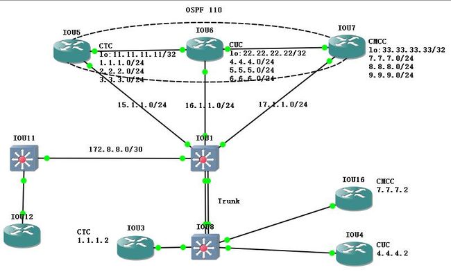
拓扑结构如下:
先说下整个拓扑情况:
电信专线接入:购买了3个C的地址给客户使用
【1.1.1.0/24、2.2.2.0/24、3.3.3.0/24】
联通专线接入:购买3个C
【4.4.4.0/24、5.5.5.0/24、6.6.6.0/24】
移动专线接入:购买3个C
【7.7.7.0/24、8.8.8.0/24、9.9.9.0/24】
中间一些的网络设备接入,均是普通的trunk透传和三层接入。这个不是今天聊的重点。所以不做赘述。
有三台模拟三个不同产商的接入PC。
CTC:1.1.1.2 =IOU3
CUC:4.4.4.2 =IOU4
CMCC:7.7.7.2 =IOU16
三个运营商起了OSPF,将9个C的业务网段全部宣告。即:三个运营商均有各自的业务网段的路由。这种做法在国内经常会有一些非(CTC\CUC\CMCC)的运营商去做的。即:三网融合的概念。我这里为了方便大家直观的感受PBR的功能实现。
核心交换机配置如下:
电信运营商:
interface Ethernet0/1
no switchport
ip address 15.1.1.1 255.255.255.0 #电信link ip
!
interface Ethernet0/2
no switchport
ip address 16.1.1.1 255.255.255.0 #联通link ip
!
interface Ethernet0/3
no switchport
ip address 17.1.1.1 255.255.255.0 #移动link ip
interface Vlan10 #SVI接口,9个C的地址,数据全部做到一起。
ip address 1.1.1.1 255.255.255.0
ip address 2.2.2.1 255.255.255.0 secondary
ip address 3.3.3.1 255.255.255.0 secondary
ip address 4.4.4.1 255.255.255.0 secondary
ip address 5.5.5.1 255.255.255.0 secondary
ip address 7.7.7.1 255.255.255.0 secondary
ip address 6.6.6.1 255.255.255.0 secondary
ip address 8.8.8.1 255.255.255.0 secondary
ip address 9.9.9.1 255.255.255.0 secondary
ip route 0.0.0.0 0.0.0.0 15.1.1.5 #默认路由指向电信
电信侧接口配置:
interface Loopback0
ip address 11.11.11.11 255.255.255.255 【电信环回测试地址】
!
interface Ethernet0/0
ip address 15.1.1.5 255.255.255.0
!
interface Ethernet7/0
ip address 56.1.1.5 255.255.255.0
联通侧接口配置:
interface Loopback0
ip address 22.22.22.22 255.255.255.255 【联通环回测试地址】
!
interface Ethernet0/0
ip address 16.1.1.6 255.255.255.0
!
interface Ethernet7/1
ip address 56.1.1.6 255.255.255.0
!
interface Ethernet7/2
ip address 67.1.1.6 255.255.255.0
!
移动侧接口配置:
interface Loopback0
ip address 33.33.33.33 255.255.255.255 【移动环回测试地址】
!
interface Ethernet0/0
ip address 17.1.1.7 255.255.255.0
!
interface Ethernet7/3
ip address 67.1.1.7 255.255.255.0
!
电信运营商的路由配置:
router ospf 110
router-id 11.11.11.11
redistribute static subnets 【将静态路由发布到ospf进程里面】
network 11.11.11.11 0.0.0.0 area 0
network 15.1.1.5 0.0.0.0 area 0
network 56.1.1.5 0.0.0.0 area 0
ip route 1.1.1.0 255.255.255.0 15.1.1.1
ip route 2.2.2.0 255.255.255.0 15.1.1.1
ip route 3.3.3.0 255.255.255.0 15.1.1.1
联通运营商的路由配置:
router ospf 110
router-id 22.22.22.22
redistribute static subnets 【将静态路由发布到ospf进程里面】
network 22.22.22.22 0.0.0.0 area 0
network 56.1.1.6 0.0.0.0 area 0
network 67.1.1.6 0.0.0.0 area 0
ip route 4.4.4.0 255.255.255.0 16.1.1.1
ip route 5.5.5.0 255.255.255.0 16.1.1.1
ip route 6.6.6.0 255.255.255.0 16.1.1.1
移动运营商的路由配置:
router ospf 110
router-id 33.33.33.33
redistribute static subnets 【将静态路由发布到ospf进程里面】
network 17.1.1.7 0.0.0.0 area 0
network 33.33.33.33 0.0.0.0 area 0
network 67.1.1.7 0.0.0.0 area 0
ip route 7.7.7.0 255.255.255.0 17.1.1.1
ip route 8.8.8.0 255.255.255.0 17.1.1.1
ip route 9.9.9.0 255.255.255.0 17.1.1.1
接入交换机的配置和汇聚交换机的配置这里不做赘述。所有线路均可以通,使用各个线路接入测试下来。
CTC-PC#traceroute 11.11.11.11
Type escape sequence to abort.
Tracing the route to 11.11.11.11
VRF info: (vrf in name/id, vrf out name/id)
1 1.1.1.1 2 msec 1 msec 5 msec
2 15.1.1.5 0 msec 6 msec 1 msec
CUC-PC#traceroute 22.22.22.22
Type escape sequence to abort.
Tracing the route to 22.22.22.22
VRF info: (vrf in name/id, vrf out name/id)
1 1.1.1.1 2 msec 1 msec 1 msec
2 15.1.1.5 1 msec 0 msec 2 msec
3 56.1.1.6 5 msec 1 msec 1 msec
CMCC-PC#traceroute 33.33.33.33
Type escape sequence to abort.
Tracing the route to 33.33.33.33
VRF info: (vrf in name/id, vrf out name/id)
1 1.1.1.1 1 msec 0 msec 3 msec
2 15.1.1.5 2 msec 1 msec 1 msec
3 56.1.1.6 1 msec 1 msec 1 msec
4 67.1.1.7 3 msec 2 msec 1 msec
PS:
大家观察,所有的线路均是通过电信出去,就是那条默认路由在起作用。虽然都正常走到了对应的线路上,这个没问题。【起ospf跑动态路由,不是本章介绍重点】
但是考虑到咱们国内,三大主流等其他网络提供商。以上的传输走向在一定程度上是走“异网传输过程”。大家都明白“互联互通”的说法,无非就是延迟变大嘛,这中间的原因“也不言而喻”
怎么解决,现在是本篇文章的“重点”,PBR(策略路由)
这里仅做一次“抓源ip地址的PBR”-----这个是目前第三方运营商经常使用的一种方式。
好了,直接晒配置:(切记,在核心交换机上做PBR配置)
interface Vlan10
ip address 2.2.2.1 255.255.255.0 secondary
ip address 3.3.3.1 255.255.255.0 secondary
ip address 4.4.4.1 255.255.255.0 secondary
ip address 5.5.5.1 255.255.255.0 secondary
ip address 7.7.7.1 255.255.255.0 secondary
ip address 6.6.6.1 255.255.255.0 secondary
ip address 8.8.8.1 255.255.255.0 secondary
ip address 9.9.9.1 255.255.255.0 secondary
ip address 1.1.1.1 255.255.255.0
ip policy route-map PBR
!
ip access-list extended CMCC
permit ip 7.7.7.0 0.0.0.255 any
ip access-list extended CUC
permit ip 4.4.4.0 0.0.0.255 any
!
route-map PBR permit 10
match ip address CUC
set ip next-hop 16.1.1.6
!
route-map PBR permit 20
match ip address CMCC
set ip next-hop 17.1.1.7
!
PS:为什么没有做CTC的PBR,因为我们的出口默认走的就是电信,所以无需对电信做策略路由的相关配置
接下来再次测试各线路的PC走到各自的运营商的测试地址:
CTC-PC#traceroute 11.11.11.11
Type escape sequence to abort.
Tracing the route to 11.11.11.11
VRF info: (vrf in name/id, vrf out name/id)
1 1.1.1.1 2 msec 5 msec 1 msec
2 15.1.1.5 0 msec 1 msec 0 msec
CUC-PC#traceroute 22.22.22.22
Type escape sequence to abort.
Tracing the route to 22.22.22.22
VRF info: (vrf in name/id, vrf out name/id)
1 1.1.1.1 6 msec 5 msec 6 msec
2 16.1.1.6 6 msec 6 msec 6 msec
CMCC-PC#traceroute 33.33.33.33
Type escape sequence to abort.
Tracing the route to 33.33.33.33
VRF info: (vrf in name/id, vrf out name/id)
1 1.1.1.1 1 msec 1 msec 6 msec
2 17.1.1.7 1 msec 1 msec 1 msec
好了,现在所有线路走对应的接入商,皆大欢喜。核心交换机进行debug ip policy,日志输出如下:
方便各位理解,PBR的策略配置后核心交换机的处理过程。
*Dec 19 14:18:26.590: IP: s=4.4.4.2 (Vlan10), d=22.22.22.22, len 28, policy match
*Dec 19 14:18:26.591: IP: route map PBR, item 10, permit
*Dec 19 14:18:26.591: IP: s=4.4.4.2 (Vlan10), d=22.22.22.22 (Ethernet0/2), len 28, policy routed
*Dec 19 14:18:26.591: IP: Vlan10 to Ethernet0/2 16.1.1.6
*Dec 19 14:18:26.592: IP: s=4.4.4.2 (Vlan10), d=22.22.22.22, len 28, policy match
*Dec 19 14:18:26.592: IP: route map PBR, item 10, permit
*Dec 19 14:18:26.592: IP: s=4.4.4.2 (Vlan10), d=22.22.22.22 (Ethernet0/2), len 28, policy routed
*Dec 19 14:18:26.592: IP: Vlan10 to Ethernet0/2 16.1.1.6
*Dec 19 14:18:26.597: IP: s=4.4.4.2 (Vlan10), d=22.22.22.22, len 28, policy match
*Dec 19 14:18:26.597: IP: route map PBR, item 10, permit
*Dec 19 14:18:26.597: IP: s=4.4.4.2 (Vlan10), d=22.22.22.22 (Ethernet0/2), len 28, policy routed
*Dec 19 14:18:26.597: IP: Vlan10 to Ethernet0/2 16.1.1.6
*Dec 19 14:18:26.598: IP: s=4.4.4.2 (Vlan10), d=22.22.22.22, len 28, FIB policy match
*Dec 19 14:18:26.598: IP: s=4.4.4.2 (Vlan10), d=22.22.22.22, len 28, PBR Counted
*Dec 19 14:18:26.598: IP: s=4.4.4.2 (Vlan10), d=22.22.22.22, g=16.1.1.6, len 28, FIB policy routed
*Dec 19 14:18:26.599: IP: s=4.4.4.2 (Vlan10), d=22.22.22.22, len 28, FIB policy match
*Dec 19 14:18:26.599: IP: s=4.4.4.2 (Vlan10), d=22.22.22.22, len 28, PBR Counted
CR#
*Dec 19 14:18:26.599: IP: s=4.4.4.2 (Vlan10), d=22.22.22.22, g=16.1.1.6, len 28, FIB policy routed
*Dec 19 14:18:26.600: IP: s=4.4.4.2 (Vlan10), d=22.22.22.22, len 28, FIB policy match
*Dec 19 14:18:26.600: IP: s=4.4.4.2 (Vlan10), d=22.22.22.22, len 28, PBR Counted
*Dec 19 14:18:26.600: IP: s=4.4.4.2 (Vlan10), d=22.22.22.22, g=16.1.1.6, len 28, FIB policy routed
欢迎各位,路过大侠指点,,,若有留言,小弟不胜感激
