实验环境:DynamipsGUI 2.8
实验拓扑:

实验目的:通过配置MPLS ×××,来达到192.168.1.0/24和192.168.2.0/24的内网互通
实验步骤:
一、配置IP地址:
R1:
CE1(config)#int f0/0
CE1(config-if)#ip add 192.168.1.1 255.255.255.0
CE1(config-if)#no sh
CE1(config)#int lo0 // 配置环回接口用于测试
CE1(config-if)#ip add 1.1.1 .1 255.255.255.255
CE1(config-if)#no sh
R2:
PE1(config)#int f0/0
PE1(config-if)#ip add192.168.1.2 255.255.255.0
PE1(config-if)#no sh
PE1(config)#int f0/1
PE1(config-if)#ip add 100.1.1.1 255.255.255.252
PE1(config-if)#no sh
PE1(config-if)#int lo0
PE1(config-if)#ip add 2.2.2 .2 255.255.255.255
PE1(config-if)#no shut
R3:
P(config)#int f0/1
P(config-if)#ip add 100.1.1.2 255.255.255.252
P(config-if)#no sh
P(config)#int f0/0
P(config-if)#ip add 100.1.1.5 255.255.255.252
P(config-if)#no sh
P(config)#int lo0
P(config-if)#ip add 3.3.3 .3 255.255.255.255
P(config-if)#no sh
R4
PE2(config)#int f0/0
PE2(config-if)#ip add 100.1.1.6 255.255.255.252
PE2(config-if)#no sh
PE2(config)#int f0/1
PE2(config-if)#ip add 192.168.2.1 255.255.255.0
PE2(config-if)#no sh
PE2(config)#int lo0
PE2(config-if)#ip add 4.4.4 .4 255.255.255.255
R5:
CE2(config)#int s0/1
CE2(config-if)#ip add 192.168.2.2 255.255.255.0
CE2(config-if)#no sh
CE2(config)#int lo0
CE2(config-if)#ip add 5.5.5 .5 255.255.255.255
CE2(config-if)#no sh
配置好以后,可以在特权模式下使用“ show ip interface brief ”来查看路由器的接口信息,这里本人不再演示!!
二、配置动态路由协议OSPF(在PE1、P、PE2上做):
PE1(config)#router ospf 1
PE1(config-router)#net 100.1.1.0 0.0.0 .3 area 0
PE1(config-router)#net 2.2.2 .2 0.0.0.0 area 0
P(config)#router ospf 1
P(config-router)#net 100.1.1.0 0.0.0 .3 area 0
P(config-router)#net 3.3.3 .3 0.0.0.0 area 0
P(config-router)#net 100.1.1.4 0.0.0 .3 area 0
PE2(config)#router ospf 1
PE2(config-router)#net 100.1.1.4 0.0.0 .3 area 0
PE2(config-if)#net 4.4.4 .4 0.0.0.0 area 0
配置好以后,可以在特权模式下使用“ show ip route ”来查看路由器的路由表,本人不再演示!!
三、配置MPLS(PE和P路由器)
R2:
PE1(config)#ip cef //开启快速转发功能
PE1(config)#int f0/1
PE1(config-if)#mpls ip //在int f0/0上启用MPLS
R3:
P(config)#ip cef
P(config)#int f0/0
P(config-if)#mpls ip
P(config)#int f0/1
P(config-if)#mpls ip
R4:
PE2(config)#ip cef
PE2(config)#int f0/0
PE2(config-if)#mpls ip
配置配置好以后,可以在特权模式下使用“ show mpls ldp nei ”来查看(PE和P设备)配置信息,
四、创建×××实例(在PE设备上):
R2:
PE1(config)#ip vrf aa //在PE1上创建×××实例,名为“aa ”
PE1(config-vrf)#rd 100:1
//配置RD: 用于区分不别×××使用相同的IP,在IP包头加了RD以后,IPV4就变成了×××-IPV4,例如:***a和***b都使用网段 10.0.0 .0/8,***a的RD为100:1,***b的RD为200:1,这样就能成为唯一的标识了,RD只有在不同的×××具有相同的IP时才有用,可以在同一×××的不同site配置不一样的RD,在同一台PE下,原理上不同的×××实例有不同的IP可以有相同的RD,但是厂商为了防止客户的IP变动造成与其它客户IP一致,一般都不允许不同的×××实例配置相同的RD,比如思科就会提示” % Cannot set RD, check if it's unique”.
PE1(config-vrf)#route-target both 100:1
//配置RT (通过标识来过滤不同的×××)——route-target [export|import|both]xx:xx,例如route-target both 100:1,表示只发送和接收带有100:1标识的包,不同的×××有不同的RT,同一×××不同site的RT进出标识要相互匹配
PE1(config-vrf)#int f0/0
PE1(config-if)#ip vrf forwarding aa //将接口绑定到×××实例中
% Interface FastEthernet0/0 IP address 192.168.1.2 removed due to enabling VRF aa
//此时系统会提示接口的IP地址(f0/0)会被删除,必需重配IP,这是因为原来的IP是属于全局路由表的,现在这个接口是属于***a实例的路由表,需要重新配置IP地址(192.168.1.2 255.255.255.0)
PE1(config-if)#ip add 192.168.1.2 255.255.255.0
PE1(config-if)#no shut
R4:
PE2(config)#ip vrf bb //在PE2上创建×××实例,名为“bb ”
PE2(config-vrf)#rd 100:1
PE2(config-vrf)#route-target both 100:1
PE2(config-vrf)# int f0/1
PE2(config-if)#ip vrf forwarding bb
% Interface FastEthernet0/1 IP address 192.168.2.1 removed due to enabling VRF bb
PE2(config-if)#ip add 192.168.2.1 255.255.255.0
PE2(config-if)#no shut
五、配置动态路由协议,在CE上配置:
R1:
CE1(config)#router ospf 2
CE1(config-router)#net 192.168.1.0 0.0.0 .255 area 0
CE1(config-router)#net 1.1.1 .1 0.0.0.0 area 0
CE2(config)#router ospf 2
CE2(config-router)#net 192.168.2.0 0.0.0 .255 area 0
CE2(config-router)#net 5.5.5 .5 0.0.0.0 area 0
六、配置PE间的iBGP协议,用来承载大量私有前缀(配置MPBGP协议。PE路由器从CE路由器学习到VRF路由后,需要通过运行MPBGP协议通告给其他PE)
R2:
PE1(config)#router bgp 100
PE1(config-router)#bgp router-id 2.2.2 .2
PE1(config-router)#neighbor 4.4.4 .4 remote-as 100
PE1(config-router)#neighbor 4.4.4 .4 update-source lo0
PE1(config-router)#no synchronization
PE1(config-router)#no auto-summary
可以在特权模式下使用“show ip bgp summary ”来查看配置信息:

R4:
PE2(config)#router bgp 100
PE2(config-router)#bgp router-id 4.4.4 .4
PE2(config-router)#neighbor 2.2.2 .2 remote-as 100
PE2(config-router)#neighbor 2.2.2 .2 update-source lo0
PE2(config-router)#no synchronization
PE2(config-router)#no auto-summary

七、启用address-family ***v4的扩展团体属性:(在PE设备上做):
R2:
PE1(config)#router bgp 100
PE1(config-router)#address-family ***v4
PE1(config-router-af)#neighbor 4.4.4 .4 activate
PE1(config-router-af)#neighbor 4.4.4 .4 send-community extended
R4:
PE2(config)#router bgp 100
PE2(config-router)#address-family ***v4
PE2(config-router-af)#neighbor 2.2.2 .2 activate
PE2(config-router-af)#neighbor 2.2.2 .2 send-community extended
八、启用address-family ipv4 vrf ***a (在PE设备上配置):
R2:
PE1(config)#router bgp 100
PE1(config-router)#address-family ipv4 vrf aa
PE1(config-router-af)# no synchronization
PE1(config-router-af)# no auto-summary
R4:
PE2(config)#router bgp 100
PE2(config-router)#address-family ipv4 vrf bb
PE2(config-router-af)# no synchronization
PE2(config-router-af)# no auto-summary
九、在GBP与OSPF之间做双向重分布
R2:
PE1(config)#router bgp 100
PE1(config-router)#address-family ipv4 vrf aa
PE1(config-router-af)#redistribute ospf 2
PE1(config)#router ospf 2
PE1(config-router)#router ospf 2 vrf aa
PE1(config-router)#net 192.168.1.0 0.0.0 .255 area 0
PE1(config-router)#redistribute bgp 100 subnets
说明:在将BGP重分布到OSPF当中,因为在OSPF路由选择模式下,没有这条“address-family ipv4 vrf aa”命令,所以,输入“router ospf vrf aa”这条命令,在这个模式下宣告直连路由和将BGP重分布到OSPF当中。在PE2上也是一样:
R4:
PE2(config)#router bgp 100
PE2(config-router)#address-family ipv4 vrf bb
PE2(config-router-af)#redistribute ospf 2
PE1(config)#router ospf 2
PE1(config-router)#router ospf 2 vrf bb
PE1(config-router)#net 192.168.2.0 0.0.0 .255 area 0
PE1(config-router)#redistribute bgp 100 subnets
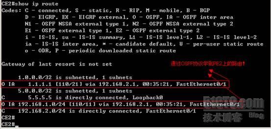
配置好以后,可以在特权模式下使用“ show ip route vrf ***名 ”来查看路由信息:


此时,可以查看CE设备上的路由表:

验证:用CE1(Source address 1.1.1 .1 ) Ping CE2 (Destination 5.5.5.5)

用CE2(Source address 5.5.5 .5 ) Ping CE1 (Destination 1.1.1.1)

在这里看到的只是两个内网能够互通,要想数据包的走向和封装过程,需要用到 “traceroute”,
路由跟踪命令,具体操作过程如下:


说明:具体的操作步骤就不再详细说明,如有不明白,可以查看本人前几篇MPLS配置过程!
实验完成!!!
此实验是在小凡模拟器上完成,需要IOS的网友可以联系本人 Q:821972656
如有看不清楚图片的,可以下载附件查看!!