实训目的
- 掌握Private Vlan的配置方法。
实训背景
在宾馆酒店、学校宿舍、小区宽带接入等场合,如果用普通VLAN技术,需要为每1个用户划分独自的VLAN才能保证隔离,但是VLAN数量有限(4094个)。
PVLAN(Private VLAN,私有VLAN),也称“专用虚拟局域网”,可以解决上述问题。PVLAN采用两层VLAN隔离技术,只有上层VLAN全局可见,下层VLAN相互隔离。可以在有限VLAN数量内(小于4094)实现多端口(大于4094)的隔离。
在物联网时代,PVLAN可用于内部网,在保证各个物联网设备都能接入因特网的同时,还可用来防止各个设备之间的非授权互相通信,也可允许设备分组、组内通讯。
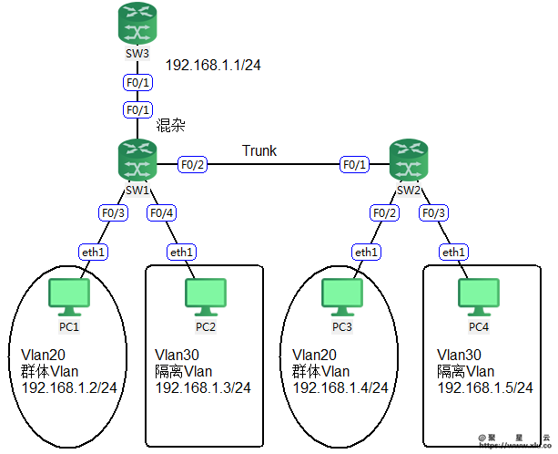
实训拓扑
实训所需设备:
| 设备类型 | 设备型号 | 数量 |
|---|---|---|
| 三层交换机 | S3760 | 3 |
| 主机 | Windows 10 | 4 |
实训步骤
步骤1:基本配置
SW1:
Ruijie>enable
Ruijie#configure terminal
Ruijie(config)#hostname SW1
SW1(config)#
SW2:
Ruijie>enable
Ruijie#configure terminal
Ruijie(config)#hostname SW2
SW2(config)#
SW3:
Ruijie>enable
Ruijie#configure terminal
Ruijie(config)#hostname SW2
SW3(config)#
步骤2:全网基本IP地址配置。
SW3#configure terminal
SW3(config)#interface fastEthernet 0/1
SW3(config-if-FastEthernet 0/1)#no switchport
SW3(config-if-FastEthernet 0/1)#ip address 192.168.1.1 255.255.255.0
SW3(config-if-FastEthernet 0/1)#exit
SW3(config)#
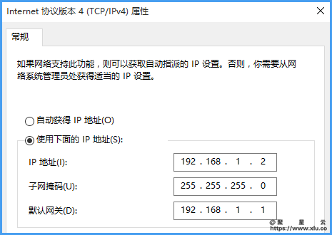
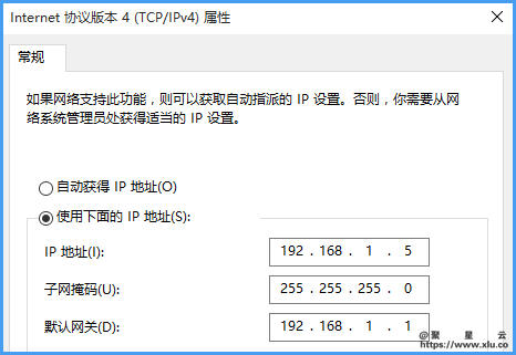
PC1:
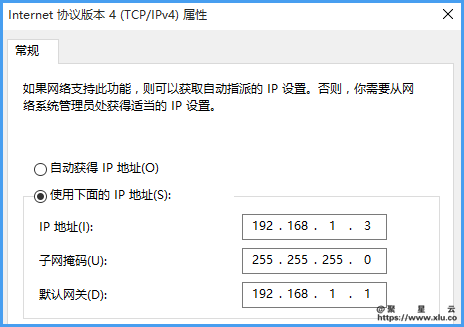
PC2:
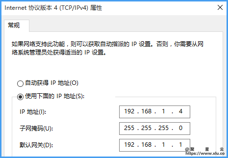
PC3:
PC4:
步骤3:启动持续ping
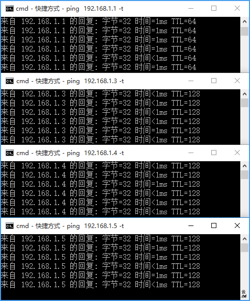
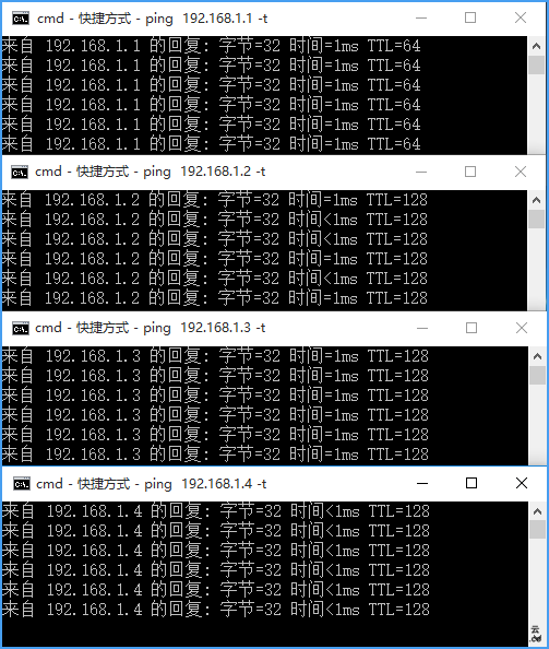
在PC1上启动4个Dos窗口进行持续ping,
ping 192.168.1.1 -t
ping 192.168.1.3 -t
ping 192.168.1.4 -t
ping 192.168.1.5 -t
并且调整Dos窗口高度,合理安排如下,以便后面持续不断的观察。
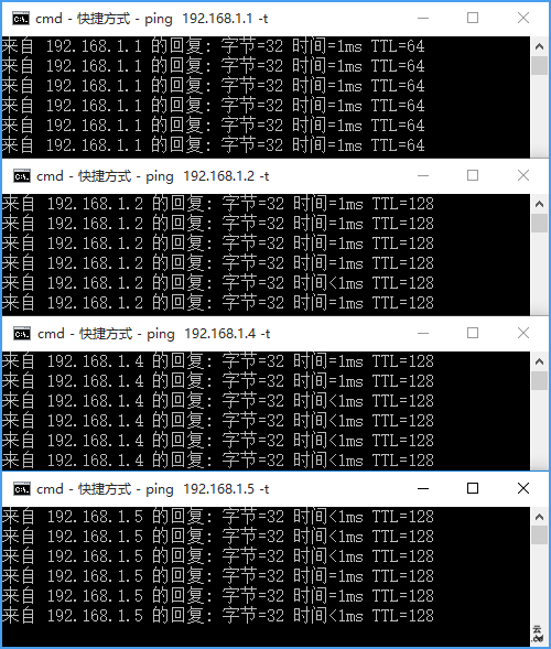
在PC2上启动4个Dos窗口进行持续ping,
ping 192.168.1.1 -t
ping 192.168.1.2 -t
ping 192.168.1.4 -t
ping 192.168.1.5 -t
并且调整Dos窗口高度,合理安排如下,以便后面持续不断的观察。
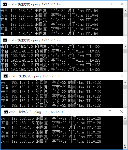
在PC3上启动4个Dos窗口进行持续ping,
ping 192.168.1.1 -t
ping 192.168.1.2 -t
ping 192.168.1.3 -t
ping 192.168.1.5 -t
并且调整Dos窗口高度,合理安排如下,以便后面持续不断的观察。
在PC4上启动4个Dos窗口进行持续ping,
ping 192.168.1.1 -t
ping 192.168.1.2 -t
ping 192.168.1.3 -t
ping 192.168.1.4 -t
并且调整Dos窗口高度,合理安排如下,以便后面持续不断的观察。
如果有双显示器的话,建议1个显示器做实训,另1个显示器显示4台PC,如下:
如果没双显示器,也没关系,只要注意以下表格ping通与否的变化即可(以下用Y表示通,N表示不通)。
| IP | PC1 | PC2 | PC3 | PC4 |
|---|---|---|---|---|
| 192.168.1.1 | Y | Y | Y | Y |
| 192.168.1.2 | Y | Y | Y | |
| 192.168.1.3 | Y | Y | Y | |
| 192.168.1.4 | Y | Y | Y | |
| 192.168.1.5 | Y | Y | Y |
步骤3:创建PVLAN
SW1(config)#vlan 20
SW1(config-vlan)#private-vlan community //创建群体Vlan20
SW1(config-vlan)#exit
SW1(config)#vlan 30
SW1(config-vlan)#private-vlan isolated //创建隔离Vlan30
SW1(config-vlan)#exit
SW1(config)#vlan 10
SW1(config-vlan)#private-vlan primary //创建主Vlan10
SW1(config-vlan)#private-vlan association 20,30 //关联辅Vlan
SW1(config-vlan)#exit
SW1(config)#
SW2(config)#vlan 20
SW2(config-vlan)#private-vlan community
SW2(config-vlan)#exit
SW2(config)#vlan 30
SW2(config-vlan)#private-vlan isolated
SW2(config-vlan)#exit
SW2(config)#vlan 10
SW2(config-vlan)#private-vlan primary
SW2(config-vlan)#private-vlan association 20,30
SW2(config-vlan)#exit
SW2(config)#
步骤4:划分端口
SW1(config)#interface fastEthernet 0/1
SW1(config-if-FastEthernet 0/1)#switchport mode trunk
SW1(config-if-FastEthernet 0/1)#switchport mode private-vlan promiscuous
SW1(config-if-FastEthernet 0/1)#switchport private-vlan mapping 10 add 20,30
SW1(config-if-FastEthernet 0/1)#exit
到这一步,因为SW1的上联口已经加入了PVLAN,而PC1-PC4所联的端口还没加入PVLAN,所以PC1-PC4 ping 192.168.1.1全部丢包。
| IP | PC1 | PC2 | PC3 | PC4 |
|---|---|---|---|---|
| 192.168.1.1 | N | N | N | N |
| 192.168.1.2 | Y | Y | Y | |
| 192.168.1.3 | Y | Y | Y | |
| 192.168.1.4 | Y | Y | Y | |
| 192.168.1.5 | Y | Y | Y |
SW1(config)#interface fastEthernet 0/2
SW1(config-if-FastEthernet 0/2)#switchport mode trunk
SW1(config-if-FastEthernet 0/2)#exit
SW1(config)#interface fastEthernet 0/3
SW1(config-if-FastEthernet 0/3)#switchport mode private-vlan host
SW1(config-if-FastEthernet 0/3)#switchport private-vlan host-association 10 20 //格式为主Vlan 辅Vlan
SW1(config-if-FastEthernet 0/3)#exit
到这一步,因为PC1所联的端口加入了PVLAN的群体Vlan20,所以如下:
| IP | PC1 | PC2 | PC3 | PC4 |
|---|---|---|---|---|
| 192.168.1.1 | Y | N | N | N |
| 192.168.1.2 | N | N | N | |
| 192.168.1.3 | N | Y | Y | |
| 192.168.1.4 | N | Y | Y | |
| 192.168.1.5 | N | Y | Y |
SW1(config)#interface fastEthernet 0/4
SW1(config-if-FastEthernet 0/4)#switchport mode private-vlan host
SW1(config-if-FastEthernet 0/4)#switchport private-vlan host-association 10 30
SW1(config-if-FastEthernet 0/4)#exit
SW1(config)#
到这一步,因为PC2所联的端口加入了PVLAN的隔离Vlan30,所以如下:
| IP | PC1 | PC2 | PC3 | PC4 |
|---|---|---|---|---|
| 192.168.1.1 | Y | Y | N | N |
| 192.168.1.2 | N | N | N | |
| 192.168.1.3 | N | N | N | |
| 192.168.1.4 | N | N | Y | |
| 192.168.1.5 | N | N | Y |
SW2(config)#interface fastEthernet 0/1
SW2(config-if-FastEthernet 0/1)#switchport mode trunk
SW2(config-if-FastEthernet 0/1)#exit
SW2(config)#interface fastEthernet 0/2
SW2(config-if-FastEthernet 0/2)#switchport mode private-vlan host
SW2(config-if-FastEthernet 0/2)#switchport private-vlan host-association 10 20
SW2(config-if-FastEthernet 0/2)#exit
到这一步,因为PC3所联的端口加入了PVLAN的群体Vlan20,所以如下:
| IP | PC1 | PC2 | PC3 | PC4 |
|---|---|---|---|---|
| 192.168.1.1 | Y | Y | Y | N |
| 192.168.1.2 | N | Y | N | |
| 192.168.1.3 | N | N | N | |
| 192.168.1.4 | Y | N | N | |
| 192.168.1.5 | N | N | N |
SW2(config)#interface fastEthernet 0/3
SW2(config-if-FastEthernet 0/3)#switchport mode private-vlan host
SW2(config-if-FastEthernet 0/3)#switchport private-vlan host-association 10 30
SW2(config-if-FastEthernet 0/3)#exit
SW2(config)#
到这一步,因为PC4所联的端口加入了PVLAN的隔离Vlan30,所以如下:
| IP | PC1 | PC2 | PC3 | PC4 |
|---|---|---|---|---|
| 192.168.1.1 | Y | Y | Y | Y |
| 192.168.1.2 | N | Y | N | |
| 192.168.1.3 | N | N | N | |
| 192.168.1.4 | Y | N | N | |
| 192.168.1.5 | N | N | N |
实训知识
按照实训一步一步做下去,我们理解了这样的规则:
- 隔离VLAN中用户只能与混杂模式的上联端口通讯(即用户能上网但不能与同级别的其他用户互访)。
- 同个群体VLAN中用户能互访,也能与混杂模式的上联端口通讯(即用户能上网也能本群体内互访)。可以设置多个群体VLAN,不同群体VLAN间用户不能互访,群体VLAN与隔离VLAN不能互访。
请牢记以下表格,加深理解。
| 主VLAN | (辅)隔离VLAN | (辅)群体VLAN | |
|---|---|---|---|
| 主VLAN | Y | Y | |
| (辅)隔离VLAN | Y | N | N |
| (辅)群体VLAN | Y | N | Y |
具体应用:在ISP实际环境中,将接入层交换机的上联端口设置为混杂模式;需要隔离的用户(例如房号101、房号102)其接入端口划分到隔离VLAN中;需要内部能互相通讯的用户(例如2楼整层)其接入端口划分到群体VLAN20中;另外一个需要内部通讯的用户(例如3楼整层)其接入端口划分到群体VLAN21中。这样就能灵活地满足用户需求。
