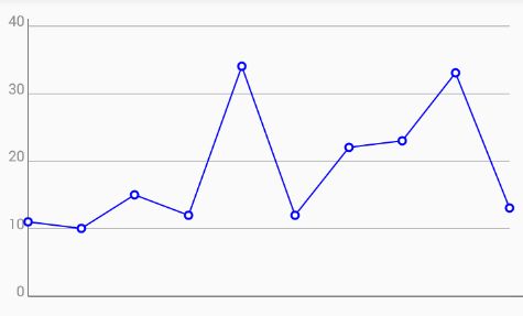
先看图
分析图表
首先我们根据上图我们可以看到如下几个元素
- 边框线
![5FXGL_@$E{Y)R{}L~1V$]7R.png](http://upload-images.jianshu.io/upload_images/6544862-a5cc5c5619226bea.png?imageMogr2/auto-orient/strip%7CimageView2/2/w/1240)
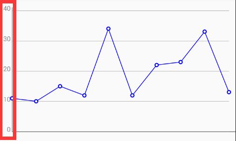
- 边框线数据值
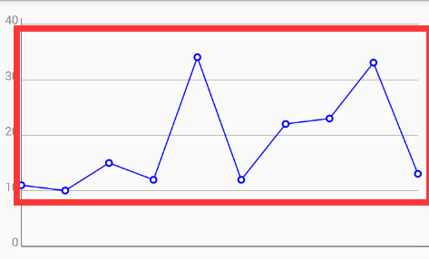
- 边框线内折线
- 折线上的圆
如上分析,我们所需要绘制的就是边框线,框线分段数据值,框内折线,折线上的圆
在画图之前 我们首先得 准备一些 必要参数
/**View宽度*/
private int mViewWidth;
/** View高度*/
private int mViewHeight;
/**边框线画笔*/
private Paint mBorderLinePaint;
/**文本画笔*/
private Paint mTextPaint;
/**要绘制的折线线画笔*/
private Paint mBrokenLinePaint;
/**圆画笔*/
private Paint mCirclePaint;
/**圆的半径*/
private float radius=5;
/**边框的左边距*/
private float mBrokenLineLeft=40;
/**边框的上边距*/
private float mBrokenLineTop=40;
/**边框的下边距*/
private float mBrokenLineBottom=40;
/**边框的右边距*/
private float mBrokenLinerRight=20;
/**需要绘制的宽度*/
private float mNeedDrawWidth;
/**需要绘制的高度*/
private float mNeedDrawHeight;
/**边框文本*/
private int[] valueText =new int[]{40,30,20,10,0};
/**数据值*/
private int[] value=new int[]{11,10,15,12,34,12,22,23,33,13};

/**图表的最大值*/
private int maxVlaue=40;
参数准备好 首先 重写onMeasure 初始化参数
@Override
protected void onMeasure(int widthMeasureSpec, int heightMeasureSpec) {
    super.onMeasure(widthMeasureSpec, heightMeasureSpec);
    mViewHeight = getMeasuredHeight();
    mViewWidth = getMeasuredWidth();
    initNeedDrawWidthAndHeight();
    initPaint();
}


/**初始化绘制折线图的宽高*/
private void initNeedDrawWidthAndHeight(){
    mNeedDrawWidth = mViewWidth-mBrokenLineLeft-mBrokenLinerRight;
    mNeedDrawHeight = mViewHeight-mBrokenLineTop-mBrokenLineBottom;
}

 /**初始化画笔*/
private void initPaint() {

    /**初始化文本画笔*/
    if(mTextPaint==null){
        mTextPaint=new Paint();
    }
    initPaint(mTextPaint);

    /**初始化边框线画笔*/
    if(mBorderLinePaint==null){
        mBorderLinePaint=new Paint();
        mBorderLinePaint.setTextSize(20);
    }
    initPaint(mBorderLinePaint);

    /**初始化折线画笔*/
    if(mBrokenLinePaint==null){
        mBrokenLinePaint=new Paint();
    }
    initPaint(mBrokenLinePaint);

    if(mCirclePaint==null){
        mCirclePaint=new Paint();
    }
    initPaint(mCirclePaint);
}

/**初始化画笔默认属性*/
private void initPaint(Paint paint){
    paint.setAntiAlias(true);
    paint.setStyle(Paint.Style.STROKE);
    paint.setColor(Color.BLACK);
}
这个时候我们的一切参数 都准备好了 首先我们来完成边线框的绘制
![5FXGL_@$E{Y)R{}L~1V$]7R.png](http://upload-images.jianshu.io/upload_images/6544862-a5cc5c5619226bea.png?imageMogr2/auto-orient/strip%7CimageView2/2/w/1240)
 /**绘制边框竖线*/
    canvas.drawLine(mBrokenLineLeft,mBrokenLineTop-10,mBrokenLineLeft,mViewHeight-mBrokenLineBottom,mBorderLinePaint);
    /**绘制边框横线*/
    canvas.drawLine(mBrokenLineLeft,mViewHeight-mBrokenLineBottom,mViewWidth,mViewHeight-mBrokenLineBottom,mBorderLinePaint);
边线框值的绘制
    /**绘制边线框的值*/
    float averageHeight=mNeedDrawHeight/(valueText.length-1);
    mBorderLinePaint.setTextAlign(Paint.Align.RIGHT);
    mBorderLinePaint.setColor(Color.GRAY);
    for (int i = 0; i < valueText.length; i++) {
        float nowadayHeight= averageHeight*i;
        canvas.drawLine(mBrokenLineLeft,nowadayHeight+mBrokenLineTop,mViewWidth-mBrokenLinerRight,nowadayHeight+mBrokenLineTop,mBorderLinePaint);
        canvas.drawText(valueText[i]+"",mBrokenLineLeft-5,nowadayHeight+mBrokenLineTop,mBorderLinePaint);
    }
绘制框内的线
/**根据值绘制折线*/
private void DrawBrokenLine(Canvas canvas) {
    Path mPath=new Path();
    mBrokenLinePaint.setColor(Color.BLUE);
    mBrokenLinePaint.setStrokeWidth(2);
    Point[] points= getPoints(value,mNeedDrawHeight,mNeedDrawWidth,maxVlaue,mBrokenLineLeft,mBrokenLineTop);
    for (int i = 0; i < points.length; i++) {
        Point point=points[i];
        if(i==0){
            mPath.moveTo(point.x,point.y);
        }else {
            mPath.lineTo(point.x,point.y);
        }

    }
    canvas.drawPath(mPath,mBrokenLinePaint);
}


/**根据值计算在该值的 x,y坐标*/
public Point[] getPoints(int[] values, float height, float width, int max , float left,float top) {
    float leftPading = width / (values.length-1);//绘制边距
    Point[] points = new Point[values.length];
    for (int i = 0; i < values.length; i++) {
        float value = values[i];
        //计算每点高度所以对应的值
        double mean = (double) max/height;
        //获取要绘制的高度
        float drawHeight = (float) (value / mean);
        int pointY = (int) (height+top  - drawHeight);
        int pointX = (int) (leftPading * i + left);
        Point point = new Point(pointX, pointY);
        points[i] = point;
    }
    return points;
}
绘制线上的圆
/**绘制线上的圆*/
private void DrawLineCircle(Canvas canvas) {
    Point[] points= getPoints(value,mNeedDrawHeight,mNeedDrawWidth,maxVlaue,mBrokenLineLeft,mBrokenLineTop);
    for (int i = 0; i
那么完整的代码如下
import android.content.Context;
import android.graphics.Canvas;
import android.graphics.Color;
import android.graphics.Paint;
import android.graphics.Path;
import android.graphics.Point;
import android.support.annotation.Nullable;
import android.util.AttributeSet;
import android.view.View;


public class BrokenLineChart extends View {
    private static final String TAG = "BrokenLineChart";
    /**View宽度*/
    private int mViewWidth;
    /** View高度*/
    private int mViewHeight;
    /**边框线画笔*/
    private Paint mBorderLinePaint;
    /**文本画笔*/
    private Paint mTextPaint;
    /**要绘制的折线线画笔*/
    private Paint mBrokenLinePaint;
    /**圆画笔*/
    private Paint mCirclePaint;
    /**圆的半径*/
    private float radius=5;
    /**边框的左边距*/
    private float mBrokenLineLeft=40;
    /**边框的上边距*/
    private float mBrokenLineTop=40;
    /**边框的下边距*/
    private float mBrokenLineBottom=40;
    /**边框的右边距*/
    private float mBrokenLinerRight=20;
    /**需要绘制的宽度*/
    private float mNeedDrawWidth;
    /**需要绘制的高度*/
    private float mNeedDrawHeight;
    /**边框文本*/
    private int[] valueText =new int[]{40,30,20,10,0};
    /**数据值*/
    private int[] value=new int[]{11,10,15,12,34,12,22,23,33,13};

    /**图表的最大值*/
    private int maxVlaue=40;
    public BrokenLineChart(Context context) {
        super(context);
    }

    public BrokenLineChart(Context context, @Nullable AttributeSet attrs) {
        super(context, attrs);
    }

    @Override
    protected void onMeasure(int widthMeasureSpec, int heightMeasureSpec) {
        super.onMeasure(widthMeasureSpec, heightMeasureSpec);
        mViewHeight = getMeasuredHeight();
        mViewWidth = getMeasuredWidth();
        initNeedDrawWidthAndHeight();
        initPaint();
    }

    @Override
    protected void onDraw(Canvas canvas) {
        super.onDraw(canvas);

        /**绘制边框线和边框文本*/
        DrawBorderLineAndText(canvas);

        /**根据数据绘制线*/
        DrawBrokenLine(canvas);
        DrawLineCircle(canvas);


    }
    /**绘制线上的圆*/
    private void DrawLineCircle(Canvas canvas) {
        Point[] points= getPoints(value,mNeedDrawHeight,mNeedDrawWidth,maxVlaue,mBrokenLineLeft,mBrokenLineTop);
for (int i = 0; i 

