Sparc V8指令
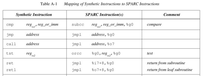
在sparc V8手册中p83(Table A-1 Mapping of Synthetic Instructions to SPARC Instructions)有合成指令synthetic instruction,这些合成指令是作为助记符mnemonic存在的,实际指令并不是这样,合成指令只是更利于记忆。
比如cmp是比较的意思,在sparc中使用subcc实现的,而cmp更好记一些;比如合成指令call的实际指令是jmpl,ret和retl的实际指令也是jmpl等。
为什么LD指令区分signed和unsigned,而ST指令不区分
LD指令有LDSB,LDSU是因为从内存加载到寄存器时,若是负数需要高位符号位扩充1。而ST指令不需要。见下面解释,v8手册p91
The load integer instructions copy a byte, a halfword, or a word from memory into r[rd]. A fetched byte or halfword is right-justified in destination register r[rd]; it is either sign-extended or zero-filled on the left, depending on whether or not the opcode specifies a signed or unsigned operation, respectively.
subcc等同于cmp
SUBcc和目的寄存器(rd=0)一起常用于有符号或无符号整数的比较,因为我们知道,比较指令(如CMP)在任何架构的机器中最终都是进行减法运算,如果结果为0,则表示两数相等。
在v8手册里,subcc是cmp指令的实际指令
Jump and Link Instruction
jmpl address, regrd
除了跳转之外,还会将PC拷贝到regrd。The JMPL instruction copies the PC, which contains the address of the JMPL instruction, into register r[rd].
Call and Link Instruction
对于Sparc来说,call实际执行的jmpl指令(这个地方有点没明白,v8手册中明确说CALL是格式1类指令p43,而且B.24还有CALL指令解释;而Table A-1中还call的实际指令是jmpl?)
call address = jmpl address,%o7,即跳转到address,同时,将PC拷贝到%o7(该寄存器用于存储跳转时的PC指针,作用类似ARM的LR)
call指令,会跳转到PC+4*disp30的地址,是延时指令
语法为call label,执行操作如下:
将label的地址拷贝到nPC(此为猜测,手册没有明确说,但因为是延时指令,估计会这么做,见后面“关于分支转移指令有一个分支延迟时隙”处解释)
将当前的PC拷贝到o7(这就是call and link中link的意思,保存中断执行的地址,共调用函数使用该链接返回,继续执行)
下面为v8手册p123的解释,其中有描述:The CALL instruction also writes the value of PC, which contains the address of the CALL, into r[15] (out register 7).
(ARM跳转有BL指令,Branch Link(Saves (PC+4) in LR and jumps to function),即首先将跳转指令的下一条指令地址保存在LR寄存器中,以便调用函数返回时能找到返回地址,然后执行跳转。)
(对于ARM,有专门的LR寄存器,对于Sparc,用o7作为LR。同时,对于ARM在调用函数中需要将LR和R11均压入堆栈;而对于Sparc,LR为o7,FP为i6,而且有寄存器窗口,因此,Sparc不需要压入堆栈操作)
Format (1):
01 disp30
31 29 0
Suggested Assembly Language Syntax
call label
Description:
The CALL instruction causes an unconditional, delayed, PC-relative control
transfer to address “PC + (4 × disp30)”. Since the word displacement
(disp30) field is 30 bits wide, the target address can be arbitrarily distant.
The PC-relative displacement is formed by appending two low-order zeros
to the instruction’s 30-bit word displacement field.
The CALL instruction also writes the value of PC, which contains the
address of the CALL, into r[15] (out register 7).
call的用法如下:
call; jmpl , %o7 mov 0, %o0
由于是延时指令,因此,最后的mov 0,%o0也会执行(o0通常用于存储返回值,即被调函数将返回值放在i0,这里的延时指令用于将返回值存储的寄存器先清零)
注释里的jmpl指令与call指令效果相同。
ret和retl指令
ret,return from subroutine,从非叶子函数返回
retl,return from leaf subroutine,从叶子函数返回
从上表看ret和retl中的l是leaf叶子的意思,不是link的意思。且两个都是通过jmpl实现的(V8手册中p83(Table A-1 Mapping of Synthetic Instructions to SPARC Instructions))。
对于非叶子函数,之前call的时候,将PC拷贝到了o7中,那么,在非叶子调用函数中,会执行save,寄存器窗口CWP=CWP-1,之前的o7变为了现在的i7,所以,跳转的目的地址是i7+8(之所以是8不是4,是因为,调用跳转是延时指令,PC+4已经执行过了,下一条执行的指令为PC+8)。
对于叶子函数,不会执行save,因此,寄存器窗口不会旋转,因此,o7中仍然为之前存储的PC,所以,跳转的目的地址是o7+8。
下面函数返回时,调用ret,实际执行的jmpl %i7+8, %g0,效果为
拷贝%i7+8到nPC(call和jmpl时会将当前PC指针拷贝到%o7中,在被调函数里为%i7,%i7+8正好为nPC的下一条指令)
将当前PC拷贝到%g0(该操作无效)
由于jmpl是延时指令,因此,后面的restore也会执行,只不过效果是restore %g0,%g0,%g0,即仅是将CWP+1
  function:
    save  %sp, -C, %sp

               ; perform. function, leave return value,
               ; if any, in register %i0 upon exit

    ret        ; jmpl %i7+8, %g0
    restore    ; restore %g0,%g0,%g0
| Figure 5 - Epilogue/prologue in procedures |
SAVE指令和RESTORE指令
SAVE指令会使CWP-1,即获得一个新的寄存器窗口。
RESTORE指令会使CWP+1,即回退到上一个窗口。
同时,
SAVE指令还具有ADD的功能,因此,save %sp, -1024, %sp,还可以为被调函数开辟1024字节的栈帧stack frame。
需要指出的是上面第一个sp在当前窗口CWP,第二个sp在新窗口CWP-1。
RESTORE指令还具有ADD的功能,因此,restore %sp, 1024, %sp,可以恢复为原来的栈帧(需要看实际汇编确认?)。
需要指出的是上面第一个sp在当前窗口CWP,第二个sp在新窗口CWP+1。
下面是v8手册p115关于save和restore的解释:
Furthermore, if and only if an overflow or underflow trap is not generated,
SAVE and RESTORE behave like normal ADD instructions, except that the
source operands r[rs1] and/or r[rs2] are read from the old window (that is,
the window addressed by the original CWP) and the sum is written into r[rd]
of the new window (that is, the window addressed by new_CWP).
对于leaf函数,并不会执行save和restore指令,下图为Peter Magnusson里的图。
  function:
               ; no save instruction needed upon entry

               ; perform function, leave return value,
               ; if any, in register %o0 upon exit

    retl       ; jmpl %o7+8, %g0
    nop        ; the delay slot can be used for something else
| Figure 6 - Epilogue/prologue in leaf procedures |
关于分支转移指令有一个分支延迟时隙
因为sparc使用了PC和nPC的机制,即nPC->PC, nPC+4->nPC。
因此,在执行branch指令时,PC=branch地址,nPC=branch+4(即branch下一条指令的地址)。
执行完branch后,nPC->PC=branch下一条指令的地址, nPC=branch目标地址。
下面是一个解释
2.分支指令延时间隙(Branch delay slot), SPARC用两个程序指针PC和nPC,来保持指令执行的轨迹。PC持有下一条要执行的指令的地址;第二个程序指针,nPC持有PC的下一个值。通常,SPARC在每一条指令执行结束时更新当前程序指针,更新时,用nPC的值代替PC的值,nPC的值则是“其原值+4”。当它执行一个转移指令时,SPARC分配nPC的值给PC,然后更新nPC的值。如果跳转发生,nPC被分配一个用指令声明的目标(地址)值;否则,nPC的值是自增4的。也就是说,跳转指令发生时,一时并没改变PC的值到目标地址,它只能执行原nPC给的下一条指令(这就产生了跳转间隙)。

    3.在跳转指令的延时间隙里不方便放有用的指令的情形时,SPARC提供 了“nop”复合指令。nop的执行,它不改变任何寄存器或内存的值。然而,它的作用是导致处理器执行更多的指令,比如,增加所需执行程序的时间。

    4.用加后缀",a"来声明跳转间隙无效。如果条件分支指令没有发生,则跳转间隙中的指令无效。如 bg ,a top。


这里讲的延时间隙是很牛的东东

在Sparc汇编中经常看到,所以要花点时间:

test.c:

    int temp;

    int x = 0;

    int y = 0x9;

    int z = 0x42;


    temp = y;

    while(temp > 0)

    {

        x = x+z;

        temp = temp-1;

    }

简单地转换,这里用到nop指令放到“分支指令延时间隙(Branch delay slot)”中。

    .data

    x: .word 0

    y: .word 0x9

    z: .word 0x42


    .text

    start: set y, %r1

    ld [%r1],%r2

    set z, %r1

    ld [%r1],%r3

    mov %r0,%r4


    add %r2, 1, %r2

    ba test

    nop !here, Branch delay slot

    top: add %r4, %r3, %r4

    test: subcc %r2, 1, %r2

    bg top

    nop !here, Branch delay slot


    set x,%r1

    st %r4,[%r1] !store x

    end: ta 0

    在上面,分支指令bg top,当发生跳转时,处理器并没有马上执行跳转,而是要执行完nop这条分支指令延时间隙中的指令后,才转移到top:处。

    Ok,在“分支指令延时间隙(Branch delay slot)”中用有用的指令。

    .data

    ......

    .text

    start: set y,%r1

    ld [%r1],%r2

    set z,%r1

    ld [%r1],%r3

    mov %r0,%r4


    add %r2, 1, %r2

    top: subcc %r2, 1, %r2

    bg,a top

    add %r4, %r3, %r4


    set x, %r1

    st %r4,[%r1]

    end: ta 0

    分支指令bg,a top,当发生跳转时,处理器并没有马上执行跳转,而是要执行完“add %r4, %r3, %r4”这条分支指令延时间隙中的指令后,才转移到top:处。而且,当跳转条件不满足时,分支指令延时间隙中的指令无效。
关于sethi指令
下面的解释很好
sethi指令

格式:

sethi const22, %reg

这个指令的作用就在于把const22放在reg的高22位,和把reg的低十位设为0。

sethi 0x333333, %L1;

0x333333 是 1100110011001100110011

经过指令作用%L1为 1100110011001100110011 0000000000

好,下面进入机智问答时间:

    Q:为什么要这样的一条指令?

    A:目的在于把一个32位的常数(比如:地址)放入寄存器。因为你不可能用一条指令来完成这个功能,(因为所有的指令都是32位长,其中还包括操作命令、标志位等)所以用这个指令再配合(add或者or)把底位补上,就能很好的解决问题。

例如,把%L1设为0x89abcdef:

1.把0x89abcdef分为高22位和底10位

    89abcdef = 10001001101010111100110111101111

    高22位:1000100110101011110011 = 226ae3

    底10位:0111101111 = 1ef

2.把这两部分分别的放进%L1

    sethi 0x226af3, %L1

    or %L1, 0x1ef, %L1

    看完后,你心里也许开始骂指令的开发者,这不是傻A的后面吗?每次放一个数我都得自己拆分一次?

    呵呵,还记得开始介绍的%hi(X)和%lo(X)吗?前一个指令就是获得常数X的高22位,后一个就是获得常数X底10位。

所以,我们可以这样做:

    sethi %hi(0x89abcdef), %L1

    or %L1, lo(0x89abcdef), %L1

    不过这也挺麻烦的,我们可以使用一条等效的组合指令:set(它不是真正的sparc指令,其实就是把sethi...or...封装起来)。

    set const32, %reg
关于寄存器窗口
在频繁调用的程序中,寄存器窗口可以加快程序执行速度。
下面是来自Peter Magnusson《Understanding stacks and registers in the Sparcarchitecture(s)》的一段解释
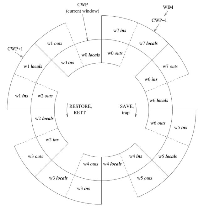
At any given time, only one window is visible, as determined by the current window pointer (CWP) which is part of the processor status register (PSR). This is a five bit value that can be decremented or incremented by the SAVE and RESTORE instructions, respectively. These instructions are generally executed on procedure call and return (respectively). The idea is that the in registers contain incoming parameters, the local register constitute scratch registers, the out registers contain outgoing parameters, and the global registers contain values that vary little between executions. The register windows overlap partially, thus the out registers become renamed by SAVE to become the in registers of the called procedure. Thus, the memory traffic is reduced when going up and down the procedure call. Since this is a frequent operation, performance is improved.

(That was the idea, anyway. The drawback is that upon interactions with the system the registers need to be flushed to the stack, necessitating a long sequence of writes to memory of data that is often mostly garbage. Register windows was a bad idea that was caused by simulation studies that considered only programs in isolation, as opposed to multitasking workloads, and by considering compilers with poor optimization. It also caused considerable problems in implementing high-end Sparc processors such as the SuperSparc, although more recent implementations have dealt effectively with the obstacles. Register windows is now part of the compatibility legacy and not easily removed from the architecture.)
寄存器窗口可以看作是堆栈的缓存。通过寄存器窗口,可以避免在调用过程中将寄存器的数据拷贝到堆栈中。
窗口用完了会产生溢出overflow trap(将reg写入存储器),所有窗口都空了会产生下溢underflow trap(从存储器加载到reg)。
The "WIM" register is also indicated in the top left of figure 1. The window invalid mask is a bit map of valid windows. It is generally used as a pointer, i.e. exactly one bit is set in the WIM register indicating which window is invalid (in the figure it's window 7). Register windows are generally used to support procedure calls, so they can be viewed as a cache of the stack contents. The WIM "pointer" indicates how many procedure calls in a row can be taken without writing out data to memory. In the figure, the capacity of the register windows is fully utilized. An additional call will thus exceed capacity, triggering a window overflow trap. At the other end, a window underflow trap occurs when the register window "cache" if empty and more data needs to be fetched from memory.
下图来自v8手册p27
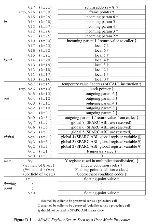
关于寄存器的用法,v8手册p189
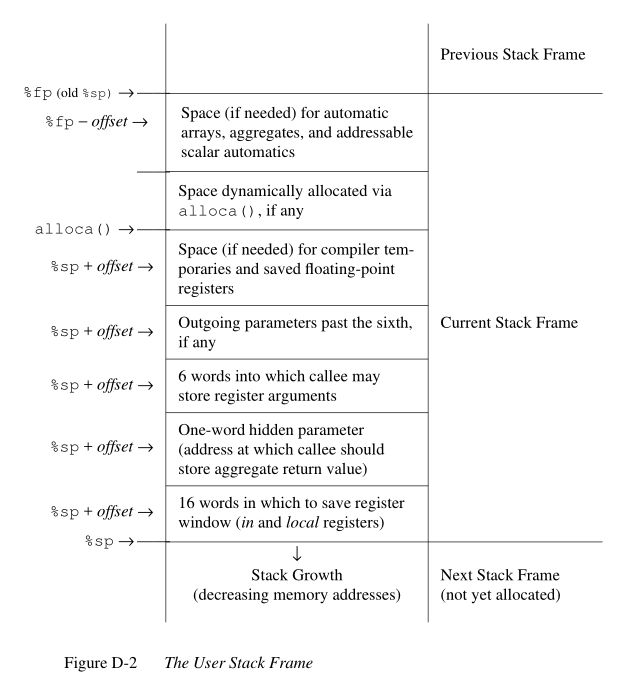
关于堆栈
fp=frame pointer,sp=stack pointer
sp最开始的16个字预留给操作系统,用于在中断、异常、陷阱发生时,存储in和local寄存器,共64字节。见下面解释:
The sparc register windows are, naturally, intimately related to the stack. In particular, the stack pointer (%sp or %o6) must always point to a free block of 64 bytes. This area is used by the operating system (Solaris, SunOS, and Linux at least) to save the current local and in registers upon a system interupt, exception, or trap instruction. (Note that this can occur at any time.)
下图来自v8手册p191
关于函数调用
SAVE指令会使CWP-1,即获得一个新的寄存器窗口。
同时,SAVE指令还具有ADD的功能,因此,save %sp, -1024, %sp,还可以为被调函数开辟1024字节的栈帧stack frame。
需要指出的是上面第一个sp在当前窗口CWP,第二个sp在新窗口CWP-1。
下面是v8手册p115关于save的解释:
Furthermore, if and only if an overflow or underflow trap is not generated,
SAVE and RESTORE behave like normal ADD instructions, except that the
source operands r[rs1] and/or r[rs2] are read from the old window (that is,
the window addressed by the original CWP) and the sum is written into r[rd]
of the new window (that is, the window addressed by new_CWP).
下面是一段解释
Procedure epilogue and prologue
The stack frame. described in the previous section leads to the standard entry/exit mechanisms listed in figure 5.
  function:
    save  %sp, -C, %sp

               ; perform. function, leave return value,
               ; if any, in register %i0 upon exit

    ret        ; jmpl %i7+8, %g0
    restore    ; restore %g0,%g0,%g0
Figure 5 - Epilogue/prologue in procedures
The SAVE instruction decrements the CWP, as discussed earlier, and also performs an addition. The constant "C" that is used in the figure to indicate the amount of space to make on the stack, and thus corresponds to the frame. contents in Figure 3. The minimum is therefore the 16 words for the LOCAL and IN registers, i.e. (hex) 0x40 bytes.

A confusing element of the SAVE instruction is that the source operands (the first two parameters) are read from the old register window, and the destination operand (the rightmost parameter) is written to the new window. Thus, allthough "%sp" is indicated as both source and destination, the result is actually written into the stack pointer of the new window (the source stack pointer becomes renamed and is now the frame. pointer).
以下3点,第1、2点可以理解,第3点还没太理解?
* If r[0] is addressed as a source operand (rs1 = 0 or rs2 = 0, or rd = 0 for a
Store) the constant value 0 is read. When r[0] is used as a destination
operand (rd = 0, excepting Stores), the data written is discarded (no r regis-
ter is modified).
* The CALL instruction writes its own address into register r[15] (out register
7).
* When a trap occurs, the program counters PC and nPC are copied into regis-
ters r[17] and r[18] (local registers 1 and 2) of the trap’s new register win-
dow.
参考资料:
https://blog.csdn.net/macrossdzh/article/details/8168473
Peter Magnusson《Understanding stacks and registers in the Sparcarchitecture(s)》
http://icps.u-strasbg.fr/people/loechner/public_html/enseignement/SPARC/sparcstack.html
附录:《Understanding stacks and registers in the Sparcarchitecture(s)》 The Sparc architecture from Sun Microsystems has some "interesting" characteristics. After having to deal with both compiler, interpreter, OS emulator, and OS porting issues for the Sparc, I decided to gather notes and documentation in one place. If there are any issues you don't find addressed by this page, or if you know of any similar Net resources, let me know. This document is limited to the V8 version of the architecture. General Structure Sparc has 32 general purpose integer registers visible to the program at any given time. Of these, 8 registers are global registers and 24 registers are in a register window. A window consists of three groups of 8 registers, the out, local, and in registers. See table 1. A Sparc implementation can have from 2 to 32 windows, thus varying the number of registers from 40 to 520. Most implentations have 7 or 8 windows. The variable number of registers is the principal reason for the Sparc being "scalable". At any given time, only one window is visible, as determined by the current window pointer (CWP) which is part of the processor status register (PSR). This is a five bit value that can be decremented or incremented by the SAVE and RESTORE instructions, respectively. These instructions are generally executed on procedure call and return (respectively). The idea is that the in registers contain incoming parameters, the local register constitute scratch registers, the out registers contain outgoing parameters, and the global registers contain values that vary little between executions. The register windows overlap partially, thus the out registers become renamed by SAVE to become the in registers of the called procedure. Thus, the memory traffic is reduced when going up and down the procedure call. Since this is a frequent operation, performance is improved. (That was the idea, anyway. The drawback is that upon interactions with the system the registers need to be flushed to the stack, necessitating a long sequence of writes to memory of data that is often mostly garbage. Register windows was a bad idea that was caused by simulation studies that considered only programs in isolation, as opposed to multitasking workloads, and by considering compilers with poor optimization. It also caused considerable problems in implementing high-end Sparc processors such as the SuperSparc, although more recent implementations have dealt effectively with the obstacles. Register windows is now part of the compatibility legacy and not easily removed from the architecture.) Register Group Mnemonic Register Address global %g0-%g7 r[0]-r[7] out %o0-%o7 r[8]-r[15] local %l0-%l7 r[16]-r[23] in %i0-%i7 r[24]-r[31] Table 1 - Visible Registers The overlap of the registers is illustrated in figure 1. The figure shows an implementation with 8 windows, numbered 0 to 7 (labeled w0 to w7 in the figure).. Each window corresponds to 24 registers, 16 of which are shared with "neighboring" windows. The windows are arranged in a wrap-around manner, thus window number 0 borders window number 7. The common cause of changing the current window, as pointed to by CWP, is the RESTORE and SAVE instuctions, shown in the middle. Less common is the supervisor RETT instruction (return from trap) and the trap event (interrupt, exception, or TRAP instruction). The "WIM" register is also indicated in the top left of figure 1. The window invalid mask is a bit map of valid windows. It is generally used as a pointer, i.e. exactly one bit is set in the WIM register indicating which window is invalid (in the figure it's window 7). Register windows are generally used to support procedure calls, so they can be viewed as a cache of the stack contents. The WIM "pointer" indicates how many procedure calls in a row can be taken without writing out data to memory. In the figure, the capacity of the register windows is fully utilized. An additional call will thus exceed capacity, triggering a window overflow trap. At the other end, a window underflow trap occurs when the register window "cache" if empty and more data needs to be fetched from memory. Register Semantics The Sparc Architecture includes recommended software semantics. These are described in the architecture manual, the Sparc ABI (application binary interface) standard, and, unfortunately, in various other locations as well (including header files and compiler documentation). Figure 2 shows a summary of register contents at any given time. %g0 (r00) always zero %g1 (r01) [1] temporary value %g2 (r02) [2] global 2 global %g3 (r03) [2] global 3 %g4 (r04) [2] global 4 %g5 (r05) reserved for SPARC ABI %g6 (r06) reserved for SPARC ABI %g7 (r07) reserved for SPARC ABI %o0 (r08) [3] outgoing parameter 0 / return value from callee %o1 (r09) [1] outgoing parameter 1 %o2 (r10) [1] outgoing parameter 2 out %o3 (r11) [1] outgoing parameter 3 %o4 (r12) [1] outgoing parameter 4 %o5 (r13) [1] outgoing parameter 5 %sp, %o6 (r14) [1] stack pointer %o7 (r15) [1] temporary value / address of CALL instruction %l0 (r16) [3] local 0 %l1 (r17) [3] local 1 %l2 (r18) [3] local 2 local %l3 (r19) [3] local 3 %l4 (r20) [3] local 4 %l5 (r21) [3] local 5 %l6 (r22) [3] local 6 %l7 (r23) [3] local 7 %i0 (r24) [3] incoming parameter 0 / return value to caller %i1 (r25) [3] incoming parameter 1 %i2 (r26) [3] incoming parameter 2 in %i3 (r27) [3] incoming parameter 3 %i4 (r28) [3] incoming parameter 4 %i5 (r29) [3] incoming parameter 5 %fp, %i6 (r30) [3] frame. pointer %i7 (r31) [3] return address - 8 Notes: [1] assumed by caller to be destroyed (volatile) across a procedure call [2] should not be used by SPARC ABI library code [3] assumed by caller to be preserved across a procedure call Figure 2 - Sparc register semantics Particular compilers are likely to vary slightly. Note that globals %g2-%g4 are reserved for the "application", which includes libraries and compiler. Thus, for example, libraries may overwrite these registers unless they've been compiled with suitable flags. Also, the "reserved" registers are presumed to be allocated (in the future) bottom-up, i.e. %g7 is currently the "safest" to use. Optimizing linkers and interpreters are exmples that use global registers. Register Windows and the Stack The sparc register windows are, naturally, intimately related to the stack. In particular, the stack pointer (%sp or %o6) must always point to a free block of 64 bytes. This area is used by the operating system (Solaris, SunOS, and Linux at least) to save the current local and in registers upon a system interupt, exception, or trap instruction. (Note that this can occur at any time.) Other aspects of register relations with memory are programming convention. The typical, and recommended, layout of the stack is shown in figure 3. The figure shows a stack frame. low addresses +-------------------------+ %sp --> | 16 words for storing | | LOCAL and IN registers | +-------------------------+ | one-word pointer to | | aggregate return value | +-------------------------+ | 6 words for callee | | to store register | | arguments | +-------------------------+ | outgoing parameters | | past the 6th, if any | +-------------------------+ | space, if needed, for | | compiler temporaries | | and saved floating- | | point registers | +-------------------------+ +-------------------------+ | space dynamically | | allocated via the | | alloca() library call | +-------------------------+ | space, if needed, for | | automatic arrays, | | aggregates, and | | addressable scalar | | automatics | +-------------------------+ %fp --> high addresses Figure 3 - Stack frame. contents Note that the top boxes of figure 3 are addressed via the stack pointer (%sp), as positive offsets (including zero), and the bottom boxes are accessed over the frame. pointer using negative offsets (excluding zero), and that the frame. pointer is the old stack pointer. This scheme allows the separation of information known at compile time (number and size of local parameters, etc) from run-time information (size of blocks allocated by alloca()). "addressable scalar automatics" is a fancy name for local variables. The clever nature of the stack and frame. pointers are that they are always 16 registers apart in the register windows. Thus, a SAVE instruction will make the current stack pointer into the frame. pointer and, since the SAVE instruction also doubles as an ADD, create a new stack pointer. Figure 4 illustrates what the top of a stack might look like during execution. (The listing is from the "pwin" command in the SimICS simulator.) REGISTER WINDOWS +--+---+----------+ |g0|r00|0x00000000| global |g1|r01|0x00000006| registers |g2|r02|0x00091278| g0-g7 |g3|r03|0x0008ebd0| |g4|r04|0x00000000| (note: 'save' and 'trap' decrements CWP, |g5|r05|0x00000000| i.e. moves it up on this diagram. 'restore' |g6|r06|0x00000000| and 'rett' increments CWP, i.e. down) |g7|r07|0x00000000| +--+---+----------+ CWP (2) |o0|r08|0x00000002| |o1|r09|0x00000000| MEMORY |o2|r10|0x00000001| o0-o7 |o3|r11|0x00000001| stack growth |o4|r12|0x000943d0| |o5|r13|0x0008b400| ^ |sp|r14|0xdffff9a0| ----\ /|\ |o7|r15|0x00062abc| | | addresses +--+---+----------+ | +--+----------+ virtual physical |l0|r16|0x00087c00| \---> |l0|0x00000000| 0xdffff9a0 0x000039a0 top of frame. 0 |l1|r17|0x00027fd4| |l1|0x00000000| 0xdffff9a4 0x000039a4 |l2|r18|0x00000000| |l2|0x0009df80| 0xdffff9a8 0x000039a8 l0-l7 |l3|r19|0x00000000| |l3|0x00097660| 0xdffff9ac 0x000039ac |l4|r20|0x00000000| |l4|0x00000014| 0xdffff9b0 0x000039b0 |l5|r21|0x00097678| |l5|0x00000001| 0xdffff9b4 0x000039b4 |l6|r22|0x0008b400| |l6|0x00000004| 0xdffff9b8 0x000039b8 |l7|r23|0x0008b800| |l7|0x0008dd60| 0xdffff9bc 0x000039bc +--+--+---+----------+ +--+----------+ CWP+1 (3) |o0|i0|r24|0x00000002| |i0|0x00091048| 0xdffff9c0 0x000039c0 |o1|i1|r25|0x00000000| |i1|0x00000011| 0xdffff9c4 0x000039c4 |o2|i2|r26|0x0008b7c0| |i2|0x00091158| 0xdffff9c8 0x000039c8 i0-i7 |o3|i3|r27|0x00000019| |i3|0x0008d370| 0xdffff9cc 0x000039cc |o4|i4|r28|0x0000006c| |i4|0x0008eac4| 0xdffff9d0 0x000039d0 |o5|i5|r29|0x00000000| |i5|0x00000000| 0xdffff9d4 0x000039d4 |o6|fp|r30|0xdffffa00| ----\ |fp|0x00097660| 0xdffff9d8 0x000039d8 |o7|i7|r31|0x00040468| | |i7|0x00000000| 0xdffff9dc 0x000039dc +--+--+---+----------+ | +--+----------+ | |0x00000001| 0xdffff9e0 0x000039e0 parameters | |0x00000002| 0xdffff9e4 0x000039e4 | |0x00000040| 0xdffff9e8 0x000039e8 | |0x00097671| 0xdffff9ec 0x000039ec | |0xdffffa68| 0xdffff9f0 0x000039f0 | |0x00024078| 0xdffff9f4 0x000039f4 | |0x00000004| 0xdffff9f8 0x000039f8 | |0x0008dd60| 0xdffff9fc 0x000039fc +--+------+----------+ | +--+----------+ |l0| |0x00087c00| \---> |l0|0x00091048| 0xdffffa00 0x00003a00 top of frame. 1 |l1| |0x000c8d48| |l1|0x0000000b| 0xdffffa04 0x00003a04 |l2| |0x000007ff| |l2|0x00091158| 0xdffffa08 0x00003a08 |l3| |0x00000400| |l3|0x000c6f10| 0xdffffa0c 0x00003a0c |l4| |0x00000000| |l4|0x0008eac4| 0xdffffa10 0x00003a10 |l5| |0x00088000| |l5|0x00000000| 0xdffffa14 0x00003a14 |l6| |0x0008d5e0| |l6|0x000c6f10| 0xdffffa18 0x00003a18 |l7| |0x00088000| |l7|0x0008cd00| 0xdffffa1c 0x00003a1c +--+--+---+----------+ +--+----------+ CWP+2 (4) |i0|o0| |0x00000002| |i0|0x0008cb00| 0xdffffa20 0x00003a20 |i1|o1| |0x00000011| |i1|0x00000003| 0xdffffa24 0x00003a24 |i2|o2| |0xffffffff| |i2|0x00000040| 0xdffffa28 0x00003a28 |i3|o3| |0x00000000| |i3|0x0009766b| 0xdffffa2c 0x00003a2c |i4|o4| |0x00000000| |i4|0xdffffa68| 0xdffffa30 0x00003a30 |i5|o5| |0x00064c00| |i5|0x000253d8| 0xdffffa34 0x00003a34 |i6|o6| |0xdffffa70| ----\ |i6|0xffffffff| 0xdffffa38 0x00003a38 |i7|o7| |0x000340e8| | |i7|0x00000000| 0xdffffa3c 0x00003a3c +--+--+---+----------+ | +--+----------+ | |0x00000001| 0xdffffa40 0x00003a40 parameters | |0x00000000| 0xdffffa44 0x00003a44 | |0x00000000| 0xdffffa48 0x00003a48 | |0x00000000| 0xdffffa4c 0x00003a4c | |0x00000000| 0xdffffa50 0x00003a50 | |0x00000000| 0xdffffa54 0x00003a54 | |0x00000002| 0xdffffa58 0x00003a58 | |0x00000002| 0xdffffa5c 0x00003a5c | | . | | | . | .. etc (another 16 bytes) | | . | Figure 4 - Sample stack contents Note how the stack contents are not necessarily synchronized with the registers. Various events can cause the register windows to be "flushed" to memory, including most system calls. A programmer can force this update by using ST_FLUSH_WINDOWS trap, which also reduces the number of valid windows to the minimum of 1. Writing a library for multithreaded execution is an example that requires explicit flushing, as is longjmp(). Procedure epilogue and prologue The stack frame. described in the previous section leads to the standard entry/exit mechanisms listed in figure 5. function: save %sp, -C, %sp ; perform. function, leave return value, ; if any, in register %i0 upon exit ret ; jmpl %i7+8, %g0 restore ; restore %g0,%g0,%g0 Figure 5 - Epilogue/prologue in procedures The SAVE instruction decrements the CWP, as discussed earlier, and also performs an addition. The constant "C" that is used in the figure to indicate the amount of space to make on the stack, and thus corresponds to the frame. contents in Figure 3. The minimum is therefore the 16 words for the LOCAL and IN registers, i.e. (hex) 0x40 bytes. A confusing element of the SAVE instruction is that the source operands (the first two parameters) are read from the old register window, and the destination operand (the rightmost parameter) is written to the new window. Thus, allthough "%sp" is indicated as both source and destination, the result is actually written into the stack pointer of the new window (the source stack pointer becomes renamed and is now the frame. pointer). The return instructions are also a bit particular. ret is a synthetic instruction, corresponding to jmpl (jump linked). This instruction jumps to the address resulting from adding 8 to the %i7 register. The source instruction address (the address of the ret instruction itself) is written to the %g0 register, i.e. it is discarded. The restore instruction is similarly a synthetic instruction, and is just a short form. for a restore that choses not to perform. an addition. The calling instruction, in turn, typically looks as follows: call; jmpl , %o7 mov 0, %o0 Again, the call instruction is synthetic, and is actually the same instruction that performs the return. This time, however, it is interested in saving the return address, into register %o7. Note that the delay slot is often filled with an instruction related to the parameters, in this example it sets the first parameter to zero. Note also that the return value is also generally passed in %o0. Leaf procedures are different. A leaf procedure is an optimization that reduces unnecessary work by taking advantage of the knowledge that no call instructions exist in many procedures. Thus, the save/restore couple can be eliminated. The downside is that such a procedure may only use the out registers (since the in and local registers actually belong to the caller). See Figure 6. function: ; no save instruction needed upon entry ; perform. function, leave return value, ; if any, in register %o0 upon exit retl ; jmpl %o7+8, %g0 nop ; the delay slot can be used for something else Figure 6 - Epilogue/prologue in leaf procedures Note in the figure that there is only one instruction overhead, namely the retl instruction. retl is also synthetic (return from leaf subroutine), is again a variant of the jmpl instruction, this time with %o7+8 as target. Yet another variation of epilogue is caused by tail call elimination, an optimization supported by some compilers (including Sun's C compiler but not GCC). If the compiler detects that a called function will return to the calling function, it can replace its place on the stack with the called function. Figure 7 contains an example. int foo(int n) { if (n == 0) return 0; else return bar(n); } cmp %o0,0 bne .L1 or %g0,%o7,%g1 retl or %g0,0,%o0 .L1: call bar or %g0,%g1,%o7 Figure 7 - Example of tail call elimination Note that the call instruction overwrites register %o7 with the program counter. Therefore the above code saves the old value of %o7, and restores it in the delay slot of the call instruction. If the function call is register indirect, this twiddling with %o7 can be avoided, but of course that form. of call is slower on modern processors. The benefit of tail call elimination is to remove an indirection upon return. It is also needed to reduce register window usage, since otherwise the foo() function in Figure 7 would need to allocate a stack frame. to save the program counter. A special form. of tail call elimination is tail recursion elimination, which detects functions calling themselves, and replaces it with a simple branch. Figure 8 contains an example. int foo(int n) { if (n == 0) return 1; else return (foo(n - 1)); } cmp %o0,0 be .L1 or %g0,%o0,%g1 subcc %g1,1,%g1 .L2: bne .L2 subcc %g1,1,%g1 .L1: retl or %g0,1,%o0 Figure 8 - Example of tail recursion elimination Needless to say, these optimizations produce code that is difficult to debug. Procedures, stacks, and debuggers When debugging an application, your debugger will be parsing the binary and consulting the symbol table to determine procedure entry points. It will also travel the stack frames "upward" to determine the current call chain. When compiling for debugging, compilers will generate additional code as well as avoid some optimizations in order to allow reconstructing situations during execution. For example, GCC/GDB makes sure original parameter values are kept intact somewhere for future parsing of the procedure call stack. The live in registers other than %i0 are not touched. %i0 itself is copied into a free local register, and its location is noted in the symbol file. (You can find out where variables reside by using the "info address" command in GDB.) Given that much of the semantics relating to stack handling and procedure call entry/exit code is only recommended, debuggers will sometimes be fooled. For example, the decision as to wether or not the current procedure is a leaf one or not can be incorrect. In this case a spurious procedure will be inserted between the current procedure and it's "real" parent. Another example is when the application maintains its own implicit call hierarchy, such as jumping to function pointers. In this case the debugger can easily become totally confused. The window overflow and underflow traps When the SAVE instruction decrements the current window pointer (CWP) so that it coincides with the invalid window in the window invalid mask (WIM), a window overflow trap occurs. Conversely, when the RESTORE or RETT instructions increment the CWP to coincide with the invalid window, a window underflow trap occurs. Either trap is handled by the operating system. Generally, data is written out to memory and/or read from memory, and the WIM register suitably altered. The code in Figure 9 and Figure 10 below are bare-bones handlers for the two traps. The text is directly from the source code, and sort of works. (As far as I know, these are minimalistic handlers for Sparc V8). Note that there is no way to directly access window registers other than the current one, hence the code does additional save/restore instructions. It's pretty tricky to understand the code, but figure 1 should be of help. /* a SAVE instruction caused a trap */ window_overflow: /* rotate WIM on bit right, we have 8 windows */ mov %wim,%l3 sll %l3,7,%l4 srl %l3,1,%l3 or %l3,%l4,%l3 and %l3,0xff,%l3 /* disable WIM traps */ mov %g0,%wim nop; nop; nop /* point to correct window */ save /* dump registers to stack */ std %l0, [%sp + 0] std %l2, [%sp + 8] std %l4, [%sp + 16] std %l6, [%sp + 24] std %i0, [%sp + 32] std %i2, [%sp + 40] std %i4, [%sp + 48] std %i6, [%sp + 56] /* back to where we should be */ restore /* set new value of window */ mov %l3,%wim nop; nop; nop /* go home */ jmp %l1 rett %l2 Figure 9 - window_underflow trap handler /* a RESTORE instruction caused a trap */ window_underflow: /* rotate WIM on bit LEFT, we have 8 windows */ mov %wim,%l3 srl %l3,7,%l4 sll %l3,1,%l3 or %l3,%l4,%l3 and %l3,0xff,%l3 /* disable WIM traps */ mov %g0,%wim nop; nop; nop /* point to correct window */ restore restore /* dump registers to stack */ ldd [%sp + 0], %l0 ldd [%sp + 8], %l2 ldd [%sp + 16], %l4 ldd [%sp + 24], %l6 ldd [%sp + 32], %i0 ldd [%sp + 40], %i2 ldd [%sp + 48], %i4 ldd [%sp + 56], %i6 /* back to where we should be */ save save /* set new value of window */ mov %l3,%wim nop; nop; nop /* go home */ jmp %l1 rett %l2 Figure 10 - window_underflow trap handler Note: some of the figures and data is (c) copyright Sun Microsystems. I can't imagine they would object to my usage of the material, but if you make copies you are hereby advised. Created and maintained by Peter Magnusson. Created in March 1997, last revision in April 1997.
Sparc V8 manual
BM3803手册