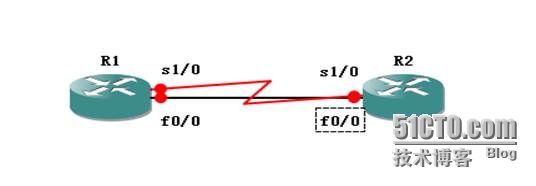
完成基础配置后分别在R1和R2上指静态:
R2(config)#ip route 1.1.1.0 255.255.255.0 12.1.1.1
R2(config)#ip route 1.1.1.0 255.255.255.0 21.1.1.1 20
在R1上起创建服务条目:
R1(config)#ip sla monitor 10
R1(config-sla-monitor)#type echo protocol ipIcmpEcho 12.1.1.2 source-ip 12.1.1.1
R1(config-sla-monitor-echo)#timeout 100
R1(config-sla-monitor-echo)#frequency 2
R1(config)#track 10 rtr 10 reachability
R1(config)#ip sla monitor schedule 10 life forever start-time now
R1(config)#ip route 2.2.2.0 255.255.255.0 21.1.1.2 20
R1(config)#ip route 2.2.2.0 255.255.255.0 12.1.1.2 track 10
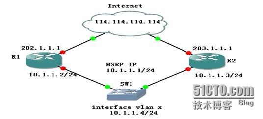
应用二:IP SLA在HSRP中的使用
Use the ip sla enable timestamp command to enable low-level time stamping for IP SLAs.
IP SLAs low-level time stamping increases the length of time between when the packet arrives at the interface and when the packet is handed to the application. For Hot Standby Router Protocol (HSRP) on a Cisco Catalyst 3560 Series switch, the longer elapsed time will exceed the default hold time at the standby interface, causing the standby HSRP to be declared active and making both (the active and standby) HSRPs active at the same time. To ensure that HSRP continues to operate correctly when the IP SLAs time stamp is enabled, also configure the standby timers command on the standby interface to increase the HSRP hello and hold timers. The recommended hello and hold timer values are 15 seconds and 16 seconds, respectively.
Router A Configuration
ip sla monitor 10
type echo protocol ipIcmpEcho 114.114.114.114 source-ipaddr 202.1.1.1
request-data-size 32
timeout 1000
frequency 3
exi
ip sla monitor schedule 10 life forever start-time now
track 20 rtr 10 reachability
interface FastEthernet0/0
ip address 10.1.1.2 255.255.255.0
standby 1 preempt
standby 1 ip 10.1.1.1
standby 1 priority 110
standby 1 track 20 decrement 10
Router B Configuration
ip sla monitor 10
type echo protocol ipIcmpEcho 114.114.114.114 source-ipaddr 203.1.1.1
request-data-size 32
timeout 1000
frequency 3
ip sla monitor schedule 10 life forever start-time now
exi
track 20 rtr 10 reachability
interface FastEthernet0/0
ip address 10.1.1.3 255.255.255.0
standby 1 preempt
standby 1 ip 10.1.1.1
standby 1 priority 105
standby 1 track 20 decrement 10
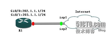
1、定义相关ACL
conf t
ip access-list extended all-net
permit ip any any
exi
access-list 1 permit 202.1.1.2
access-list 2 permit 203.1.1.2
2、Route-map、Nat
route-map isp1-line permit 10
match ip address all-net
match ip next-hop 1
exi
route-map isp2-line permit 10
match ip address all-net
match ip next-hop 2
exi
ip nat inside source route-map isp1-line int gi0/1 overload
ip nat inside source route-map isp2-line int gi0/2 overload
3、IP SlA
icmp-echo 202.1.1.2 source-ip 202.1.1.1
timeout 5000
frequency 2
exi
ip sla schedule 202 life forever start-time now
ip sla 203
icmp-echo 203.1.1.2 source-ip 203.1.1.1
timeout 5000
frequency 2
exi
ip sla schedule 203 life forever start-time now
定义SLA监视组
track 2 ip sla 203 reachability
写路由
-----------------------------------------------------------------------
R1(config)#ip route 0.0.0.0 0.0.0.0 202.1.1.2 track 1
R1(config)#ip route 0.0.0.0 0.0.0.0 203.1.1.2 track 2
1、定义相关ACL
conf t
ip access-list extended all-net
permit ip any any
exi
access-list 1 permit 202.1.1.1
access-list 2 permit 203.1.1.1
2、Route-map、Nat
route-map isp1-line permit 10
match ip address all-net
match ip next-hop 1
exi
route-map isp2-line permit 10
match ip address all-net
match ip next-hop 2
exi
ip nat inside source route-map isp1-line int fa0/1 overload
ip nat inside source route-map isp2-line int fa0/2 overload
3、IP SlA
本地路由设备到ISP中间往往连接一个光电转换器(Layer2),当对端shutdown状态,本地设备仍处于UP,这时将导致所谓的“黑洞”现象,我们可以通过SLA来做网络端到端的可用性监测,从而解决这个问题。
ip sla monitor 10
type echo protocol ipIcmpEcho 202.1.1.1 source-ipaddr 201.1.1.2
timeout 5000
frequency 2
exi
ip sla monitor schedule 10 life forever start-time now
ip sla monitor 20
type echo protocol ipIcmpEcho 203.1.1.1 source-ipaddr 202.1.1.2
timeout 5000
frequency 2
exi
ip sla monitor schedule 20 life forever start-time now
定义SLA监视组
track 1 rtr 10 reachability
track 2 rtr 20 reachability
写路由
R1(config)#ip route 0.0.0.0 0.0.0.0 202.1.1.1 track 1
R1(config)#ip route 0.0.0.0 0.0.0.0 203.1.1.1 track 2


