FreeRTOS S32K148
文章目录
- 前言
- 建立工程
- ProcessorExpert配置
- FreeRTOS代码补全
- 调试运行
- 完整工程
- 微信公众号
前言
前几节用的是ST的STM32CubeMX生成FreeRTOS工程(CMSIS-RTOS2对FreeRTOS的封装), 其实NXP的S32 Design Studio for ARM中的ProcessorExpert也集成了FreeRTOS, 而且用的是原生的FreeRTOS API, 可直接参考FreeRTOS官网查看各个函数的用法, 本节就创建一个S32K148的FreeRTOS工程, 抛砖引玉. 用到的LED1--PTE21, LED2--PTE22, 均为低电平点亮.
建立工程
步骤:
- File -> New -> S32DS Application Project
- Processors 选择 S32K148, Project Name 填你自己的工程名
- Select SDK: SDKs 选择 S32K148_SDK 3.0.0, Debugger选择J-Link, Finish.
ProcessorExpert配置
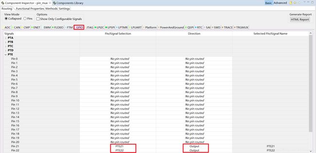
双击工程名, 点击Components窗口Components目录下的 pin_mux:PinSetting, GPIO中选择PTE21/PTE22, 并设置为Output:
Component Library中双击添加FreeRTOS组件:

点击FreeRTOS, 可以查看下各选项卡的内容, 这里默认不作修改:

点击生成代码:

FreeRTOS代码补全
添加一个新的rtos.c文件:

填入以下内容:
/* Kernel includes. */
#include "FreeRTOS.h"
#include "task.h"
#include "queue.h"
#include "timers.h"

/* SDK includes. */
#include "interrupt_manager.h"
#include "clock_manager.h"
#include "clockMan1.h"
#include "pin_mux.h"

#define LED1_PIN_INDEX  21U
#define LED2_PIN_INDEX  22U
#define LED_GPIO_PORT  PTE

/* Priorities at which the tasks are created. */
#define TASK_LED1_PRIORITY		( tskIDLE_PRIORITY + 2 )
#define	TASK_LED2_PRIORITY		( tskIDLE_PRIORITY + 2 )

/*-----------------------------------------------------------*/

static void Entry_Task_LED1( void *pvParameters );
static void Entry_Task_LED2( void *pvParameters );

/*-----------------------------------------------------------*/

void rtos_start( void )
{
	/* Configure the NVIC, LED outputs*/
    CLOCK_SYS_Init(g_clockManConfigsArr, CLOCK_MANAGER_CONFIG_CNT,
                   g_clockManCallbacksArr, CLOCK_MANAGER_CALLBACK_CNT);
    CLOCK_SYS_UpdateConfiguration(0U, CLOCK_MANAGER_POLICY_AGREEMENT);
    PINS_DRV_Init(NUM_OF_CONFIGURED_PINS, g_pin_mux_InitConfigArr);

	/* Start with LEDs off. */
    PINS_DRV_WritePins(LED_GPIO_PORT, (1 << LED1_PIN_INDEX) | (1 << LED2_PIN_INDEX));

    xTaskCreate( Entry_Task_LED1, "LED1", configMINIMAL_STACK_SIZE, NULL, TASK_LED1_PRIORITY, NULL );
    xTaskCreate( Entry_Task_LED2, "LED2", configMINIMAL_STACK_SIZE, NULL, TASK_LED2_PRIORITY, NULL );

    vTaskStartScheduler();

	/* If all is well, the scheduler will now be running, and the following line
	will never be reached.  If the following line does execute, then there was
	insufficient FreeRTOS heap memory available for the idle and/or timer tasks
	to be created.  See the memory management section on the FreeRTOS web site
	for more details. */
	for( ;; );
}

/*-----------------------------------------------------------*/

static void Entry_Task_LED1( void *pvParameters )
{
	/* Casting pvParameters to void because it is unused */
	(void)pvParameters;

	for( ;; )
	{
		PINS_DRV_TogglePins(LED_GPIO_PORT, (1 << LED1_PIN_INDEX));
		vTaskDelay(1000);
	}
}
/*-----------------------------------------------------------*/

static void Entry_Task_LED2( void *pvParameters )
{
	/* Casting pvParameters to void because it is unused */
	(void)pvParameters;

	for( ;; )
	{
		PINS_DRV_TogglePins(LED_GPIO_PORT, (1 << LED2_PIN_INDEX));
		vTaskDelay(1000);
	}
}
rtos_start完成系统和外设初始化, 创建两个点灯的任务, 然后开始任务调度, 这个函数需要在main.c补充以下代码才能调用:
/* User includes (#include below this line is not maintained by Processor Expert) */
extern void rtos_start(void);
#define PEX_RTOS_START rtos_start
如图所示:

这个很关键.
调试运行
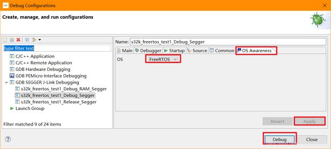
可以把调试配置的OS选成FreeRTOS:
调试运行, 发现板子上的两个LED均以1s周期翻转, 符合预期.
完整工程
https://download.csdn.net/download/weifengdq/12016933
微信公众号
欢迎扫描二维码关注我的微信公众号, 及时获取最新文章:
