将EIGRP配置到NBMA网络上
1.1.1. 所需设备
下面是做这个实验所需的设备:
1)Cisco路由器都有一个串行端口;
2) 一台具有三个串行端口的Cisco路由器;
3) Cisco 10.0版或更高;
4) 一台运行了终端仿真程序的PC;
5) 三根Cisco DTE/DCE交叉电缆;
6) 一根Cisco 扁平电缆供路由器的控制台端口访问使用。
1.1.2. 概述
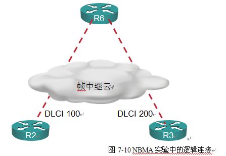
这个实验将涉及当在NBMA网络上启动了EIGRP时的水平分割问题,如帧中继,这种网络是典型的轴辐式环境。路由器R6作为轴,并定义了到每个辐的PVC,所有路由器处于同一子网中。问题在于水平分割的规则使路由器R6无法在它收到信息的物理接口通告路由信息。因为从路由器R2和R3来的PVC无法在路由器R6的物理接口终止,所以水平分割使路由器R2无法收到从路由器R3来的路由更新(见图7-10)。
1.1.3. 配置概述
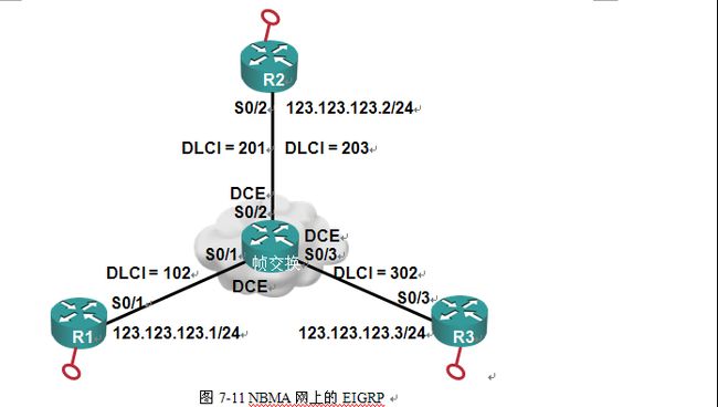
这个实验将会验证如何在帧中继上配置EIGRP。路由器R2、R6、R3通过交叉电缆串行的连接到一个Cisco路由器上,这个路由器作为帧中继开关。
帧开关将充当DEC,向所连路由器提供时钟。关于如何将一个路由器配置成一个帧中继开关的详细文档可以在第4章中找到。IP地址如图7-11所示。
1.1.4. 路由器配置
这个例子中的路由器配置如下所示:
1. 帧交换机
FrameSwitch#show running-config
!
hostname FrameSwitch
!
frame-relay switching
!
interface Serial0/1
no ip address
encapsulation frame-relay
clock rate 64000
frame-relay intf-type dce
frame-relay route 102 interface Serial0/2 201
!
interface Serial0/2
no ip address
encapsulation frame-relay
clock rate 64000
frame-relay intf-type dce
frame-relay route 201 interface Serial0/1 102
frame-relay route 203 interface Serial0/3 302
!
interface Serial0/3
no ip address
encapsulation frame-relay
clock rate 64000
frame-relay intf-type dce
frame-relay route 302 interface Serial0/2 203
!
!
end
2. 路由器R1
R1#show running-config
interface Loopback0
ip address 1.1.1 .1 255.255.255.0
!
interface Serial0/1
ip address 123.123.123.1 255.255.255.0
encapsulation frame-relay
serial restart-delay 0
frame-relay map ip 123.123.123.3 102 broadcast
frame-relay map ip 123.123.123.2 102 broadcast
!
router EIGRP 90
network 1.0.0 .0
network 123.123.123.0
auto-summary
!
!
end
3. 路由器R2
R2#show running-config
!
interface Loopback0
ip address 2.2.2 .2 255.255.255.0
!
interface Serial0/2
ip address 123.123.123.2 255.255.255.0
encapsulation frame-relay
serial restart-delay 0
frame-relay map ip 123.123.123.3 203 broadcast
frame-relay map ip 123.123.123.1 203 broadcast
!
router EIGRP 90
network 2.0.0 .0
network 123.123.123.0
auto-summary
!
!
end
4. 路由器R3
R3#show running-config
!
interface Loopback0
ip address 3.3.3 .3 255.255.255.0
!
interface Serial0/3
ip address 123.123.123.3 255.255.255.0
encapsulation frame-relay
serial restart-delay 0
frame-relay map ip 123.123.123.2 301 broadcast
frame-relay map ip 123.123.123.1 301 broadcast
!
router EIGRP 90
network 3.0.0 .0
network 123.123.123.0
auto-summary
!
!
end
1.1.5. 监测配置
使用show ip route命令显示路由器R1的路由表。注意路由器R1没有收到从网络 3.0.0 .0来的任何信息,这是因为水平分割的原因。路由器R2不会向接收路径的同一个接口发出通告。
R1#show ip route
Gateway of last resort is not set
1.0.0 .0/8 is variably subnetted, 2 subnets, 2 masks
C 1.1.1 .0/24 is directly connected, Loopback0
D 1.0.0 .0/8 is a summary, 00:01:11, Null0
D 2.0.0 .0/8 [90/2297856] via 123.123.123.2, 00:00:42, Serial0/1
123.0.0.0/8 is variably subnetted, 2 subnets, 2 masks
C 123.123.123.0/24 is directly connected, Serial0/1
D 123.0.0.0/8 is a summary, 00:01:11, Null0
使用命令no ip split horizon EIGRP 90可以取消路由器R2的水平分割。
R2#config ter
Enter configuration commands, one per line. End with CNTL/Z.
R2(config)#inter s0/2
R2(config-if)#no ip split-horizon EIGRP 90
现在显示路由器R1的路由表,注意路由器R1有一条到网络 3.0.0 .0的路径。
R1#show ip route
Gateway of last resort is not set
1.0.0 .0/8 is variably subnetted, 2 subnets, 2 masks
C 1.1.1 .0/24 is directly connected, Loopback0
D 1.0.0 .0/8 is a summary, 00:00:12, Null0
D 2.0.0 .0/8 [90/2297856] via 123.123.123.2, 00:02:36, Serial0/1
D 3.0.0 .0/8 [90/2809856] via 123.123.123.2, 00:00:12, Serial0/1
123.0.0.0/8 is variably subnetted, 2 subnets, 2 masks
C 123.123.123.0/24 is directly connected, Serial0/1
D 123.0.0.0/8 is a summary, 00:03:05, Null0

