在Unity3D中使用Visual Studio调试shader
本文主要介绍在U3D中调试shader代码的主要技术:false-color images:通过设置片元颜色中的某个分量,使得该值可视。然后根据resulting image中的颜色分量的亮度(intensity of that color component),你可以得到shader代码中的值的结论,这种技术的确是一种很原始的调试技术,但不幸的是,这在U3D中并不是不常见的。
1 顶点数据来自何方
在RGB cube一节中,你可以看到片元着色器如何通过顶点着色器输出的结构体中,获取到对应的数据。那么问现在的问题是:顶点着色器从何方拿到这些数据?在U3D环境下,答案是从绑定到game object中的Mesh Renderer组件中获取。Mesh Renderer组件将在每一帧中所有的发送网格顶点数据给OpenGL。这一步发送操作通常被称为“draw call”。必须注意的是,每一个的draw call都有一些性能耗费(performance overhead)。因而,一次性地给OpenGL发送一个大的网格数据,比分多次发送,每次发送一些较小的网格数据,要来得更高效些。这些网格数据通常由一系列的三角形组成,
而每一个三角形则是以”三个顶点数据和一些其他属性数据“的方式被定义。这些属性数据将会通过”顶点输入参数(vertex input parameter)“的方式在顶点着色器中被启用。每一个顶点输入参数将会指定一系列的语义,如POSITION, NORMAL, TEXCOORD0, TEXCOORD1, TANGENT, COLOR等等
。在U3D环境下的Cg语言的特定编程实现中。这些内建的顶点输入参数将会由一个特定的名字。
2 内建的顶点输入参数,以及如何使得它们可视
在U3D中的,内建的顶点输入参数不仅仅有特定的语义表示符号,还有特定的变量名字和类型,此外,他们还被包含在一个单独的结构体中,如下:
这个数据结构可以以下的方式被使用:
在RGB Cube一文中我们已经知道如何通过”以顶点坐标的值设置对应的片元颜色“,使得这些顶点坐标的值可视。在本文中,片元颜色将会用纹理坐标去设置,使得U3D提供的纹理坐标值是什么。
注意在vertexInput结构体的tangent成员变量中,只有前三个分量才表示该顶点的切线方向。通常在第四个分量存储的数值会用作一些特殊用途,例如用于parallex mapping。
通常,你能通过明确指定你所需的顶点输入参数的具体属性值,而不是所有的顶点属性都罗列出来,以达到较高的性能要求。U3D在UnityCG.cginc文件中提供了若干个预定义的顶点数据结构体,如appdata_base,appdata_tan,appdata_full。appdata_full结构体包含了最多的顶点属性语义。如下:
所以上一段shader代码可以使用U3D定义的顶点输入类型改写为:
3 如何解析False color image
当试图据理解一个false color image的信息的时候,只需要将重点放在一个颜色分量中即可。例如:如果我们要渲染一个标准球体。在顶点输入结构中,有一个成员变量texcoord,绑定了TEXCOORD0语义,并且这个texcoord的值写入到片元颜色中,则这个texcoord变量所包含的纹理坐标x分量值就对应于片元颜色的red分量。如果你从来没有学习过如何把注意力集中在一个颜色分量上的话,这个方式就变得挺有挑战性的。因而,你可以考虑一次只看一个颜色分量,如下代码所示:
上面的代码在顶点着色器中执行,将会把纹理坐标的x分量输出到片元颜色中red分量中,这时候如果你看效果图,则在球体上从0度开始,到360度为止,逐渐地从淡红变为深红,类似于这种方式,我们也可以把纹理坐标的y坐标输出到片元颜色的green分量中。
纹理坐标是特别容易可视化的,因为它们的值和颜色分量值类似,范围都是限定在[0,1]。类似地法线值也可以用类似的方法去可视化,但因为法线的分量值是在[-1,1]范围内,所以我们要做一个映射,将这个值域映射到[0,1]。方法如下:
如果你想可视化的数据值的值域范围不在[0,1]或者[-1,1]的话,也必须要将其值域映射到[0,1],如果你不知道待可视化的值的范围的话,你只能逐一地去尝试。在这里,如果这些待可视化的值超出了[0,1]范围的话,当输出到颜色变量时,他们自动地夹持到[0,1]范围中。即小于0值被设置为0,大于1值被设置为1.因此,当输出的颜色变量的分量是0或者1时,你至少知道这个待可视化值的分量有超过[0,1]范围了,你必须想办法将其准确地映射到[0,1]中
为了实践调试shader代码。本节包含了一些代码,这些代码用来生成黑色的颜色。你的任务是弄明白每一行代码,弄明白为何最后的输出结果是黑色在最后,你可以尝试可视化任何的你不确定的值。尝试将一些大于1或者小于0的值映射的[0,1]范围内。注意下面的代码中有很多函数和操作数在Vector and Matrix Operations这一节中有文档注解。
4 使用Visual Studio调试shader代码
首先要更新安装必须的软件,如下:
-下载和安装DirectX SDK June 2010版本
-安装最新的Windows更新补丁
-安装最新的Visual Studio更新补丁,至少是version 4
接着创建一个新的Unity3D工程,在工程中创建一个预定义的立方体game object。然后创建一个Shader文件,该shader命名为NewShader。编写NewShader代码如下:
注意在上面的代码中,enable_d3d11_debug_symbols标志一定要被启用!
在U3D的工程窗口中,右击弹出菜单,选【Create->Material】选项,创建一个新的材质
1 选中这个新创建的材质,并且给该材质指定shader为刚才创建的New Shader。
2 把这个新创建的材质拖拽到场景内的cube上。
3 点击【File->Build Settings】菜单项,在工程配置界面上选择【PC Standalone】,然后点击【Switch Platform】按钮
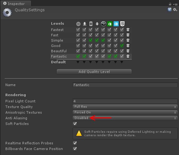
4 点击【Edit->Project Settings->Quality】菜单项,然后在Inspector面板中关闭所有画面质量等级中的反走样效果。如下图:
按下“Print Screen”键,然后切换回Visual studio。你就可以看到当前捕获的帧的画面,双击这画面,便可以打开一个新的Visual Studio窗口,如下图:
在这个新打开的Visual Studio窗口上,你可以通过鼠标滚轮放大或者缩小这个捕获的帧的大小。把十字叉丝放置到你感兴趣的那个像素点上,然后点击鼠标左键。如下图:
移动鼠标到图形事件列表窗口(Graphics Event List Window)。选择第一个出现的(在事件列表树状控件中最靠顶的那个)"obj:x DrawIndexed"事件。如果VS弹出“No source available”警告。则选择一个在Camera.Render树状控件的项,如下图:
移动到Graphics Pixel History window,在树状控件中,选中【Go to Graphics Pixel History window->obj:x DrawIndexed->Triangle->Vertex Shader】项,然后点击绿色的箭头,如下图:
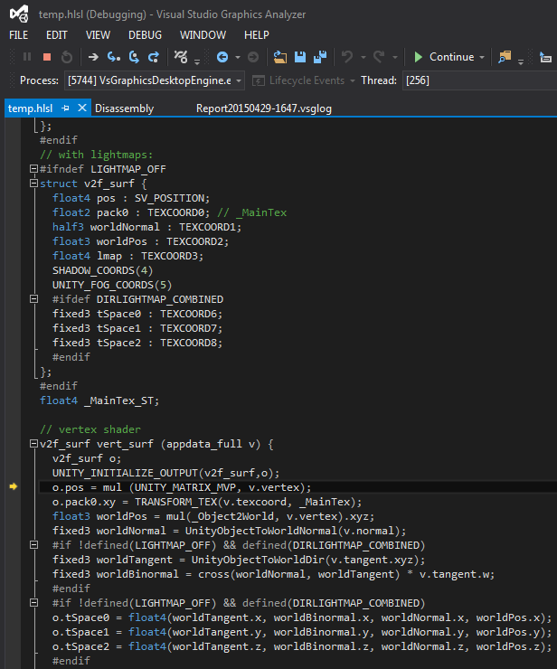
1 顶点数据来自何方
在RGB cube一节中,你可以看到片元着色器如何通过顶点着色器输出的结构体中,获取到对应的数据。那么问现在的问题是:顶点着色器从何方拿到这些数据?在U3D环境下,答案是从绑定到game object中的Mesh Renderer组件中获取。Mesh Renderer组件将在每一帧中所有的发送网格顶点数据给OpenGL。这一步发送操作通常被称为“draw call”。必须注意的是,每一个的draw call都有一些性能耗费(performance overhead)。因而,一次性地给OpenGL发送一个大的网格数据,比分多次发送,每次发送一些较小的网格数据,要来得更高效些。这些网格数据通常由一系列的三角形组成,
而每一个三角形则是以”三个顶点数据和一些其他属性数据“的方式被定义。这些属性数据将会通过”顶点输入参数(vertex input parameter)“的方式在顶点着色器中被启用。每一个顶点输入参数将会指定一系列的语义,如POSITION, NORMAL, TEXCOORD0, TEXCOORD1, TANGENT, COLOR等等
。在U3D环境下的Cg语言的特定编程实现中。这些内建的顶点输入参数将会由一个特定的名字。
2 内建的顶点输入参数,以及如何使得它们可视
在U3D中的,内建的顶点输入参数不仅仅有特定的语义表示符号,还有特定的变量名字和类型,此外,他们还被包含在一个单独的结构体中,如下:
struct vertexInput
{
  float4 vertex:POSITION; // position (in object coordinates,  i.e. local or model coordinates)
  float4 tangent:TANGENT; // vector orthogonal to the surface normal
  float3 normal:NORMAL; //surface normal vector (in object coordinates; usually normalized to unit                            //length
  float4 texcoord:TEXCOORD0; //0th set of texture coordinates (a.k.a. “UV”; between 0 and 1)
  float4 texcoord1:TEXCOORD1; //1st set of texture coordinates  (a.k.a. “UV”; between 0 and 1)
  fixed4 color:COLOR; //color (usually constant)
};
这个数据结构可以以下的方式被使用:
Shader "Cg shader with all built-in vertex input parameters" {
   SubShader {
      Pass {
         CGPROGRAM

         #pragma vertex vert
         #pragma fragment frag

         struct vertexInput {
            float4 vertex : POSITION;
            float4 tangent : TANGENT;
            float3 normal : NORMAL;
            float4 texcoord : TEXCOORD0;
            float4 texcoord1 : TEXCOORD1;
            fixed4 color : COLOR;

         };
         struct vertexOutput {
            float4 pos : SV_POSITION;
            float4 col : TEXCOORD0;
         };

         vertexOutput vert(vertexInput input)
         {
            vertexOutput output;
            output.pos =  mul(UNITY_MATRIX_MVP, input.vertex);
            output.col = input.texcoord; // set the output color

            // other possibilities to play with:
            // output.col = input.vertex;
            // output.col = input.tangent;
            // output.col = float4(input.normal, 1.0);
            // output.col = input.texcoord;
            // output.col = input.texcoord1;
            // output.col = input.color;
            return output;
         }

         float4 frag(vertexOutput input) : COLOR
         {
            return input.col;
         }

         ENDCG
      }
   }
}
在RGB Cube一文中我们已经知道如何通过”以顶点坐标的值设置对应的片元颜色“,使得这些顶点坐标的值可视。在本文中,片元颜色将会用纹理坐标去设置,使得U3D提供的纹理坐标值是什么。
注意在vertexInput结构体的tangent成员变量中,只有前三个分量才表示该顶点的切线方向。通常在第四个分量存储的数值会用作一些特殊用途,例如用于parallex mapping。
通常,你能通过明确指定你所需的顶点输入参数的具体属性值,而不是所有的顶点属性都罗列出来,以达到较高的性能要求。U3D在UnityCG.cginc文件中提供了若干个预定义的顶点数据结构体,如appdata_base,appdata_tan,appdata_full。appdata_full结构体包含了最多的顶点属性语义。如下:
struct appdata_base {
      float4 vertex : POSITION;
      float3 normal : NORMAL;
      float4 texcoord : TEXCOORD0;

};
struct appdata_tan {
      float4 vertex : POSITION;
      float4 tangent : TANGENT;
      float3 normal : NORMAL;
      float4 texcoord : TEXCOORD0;
};
struct appdata_full {
      float4 vertex : POSITION;
      float4 tangent : TANGENT;
      float3 normal : NORMAL;
      float4 texcoord : TEXCOORD0;
      float4 texcoord1 : TEXCOORD1;
      fixed4 color : COLOR;
      // and additional texture coordinates only on XBOX360)
};
所以上一段shader代码可以使用U3D定义的顶点输入类型改写为:
Shader "Cg shader with all built-in vertex input parameters" {
   SubShader {
      Pass {
         CGPROGRAM

         #pragma vertex vert
         #pragma fragment frag
         #include "UnityCG.cginc"

         struct vertexOutput {
            float4 pos : SV_POSITION;
            float4 col : TEXCOORD0;
         };

         vertexOutput vert(appdata_full input)
         {
            vertexOutput output;
            output.pos =  mul(UNITY_MATRIX_MVP, input.vertex);
            output.col = input.texcoord;
            return output;
         }

         float4 frag(vertexOutput input) : COLOR
         {
            return input.col;
         }

         ENDCG
      }
   }
}
3 如何解析False color image
当试图据理解一个false color image的信息的时候,只需要将重点放在一个颜色分量中即可。例如:如果我们要渲染一个标准球体。在顶点输入结构中,有一个成员变量texcoord,绑定了TEXCOORD0语义,并且这个texcoord的值写入到片元颜色中,则这个texcoord变量所包含的纹理坐标x分量值就对应于片元颜色的red分量。如果你从来没有学习过如何把注意力集中在一个颜色分量上的话,这个方式就变得挺有挑战性的。因而,你可以考虑一次只看一个颜色分量,如下代码所示:
output.col = float4(input.texcoord.x, 0.0, 0.0, 1.0);上面的代码在顶点着色器中执行,将会把纹理坐标的x分量输出到片元颜色中red分量中,这时候如果你看效果图,则在球体上从0度开始,到360度为止,逐渐地从淡红变为深红,类似于这种方式,我们也可以把纹理坐标的y坐标输出到片元颜色的green分量中。
纹理坐标是特别容易可视化的,因为它们的值和颜色分量值类似,范围都是限定在[0,1]。类似地法线值也可以用类似的方法去可视化,但因为法线的分量值是在[-1,1]范围内,所以我们要做一个映射,将这个值域映射到[0,1]。方法如下:
output.col = float4((input.normal + float3(1.0, 1.0, 1.0)) / 2.0, 1.0);如果你想可视化的数据值的值域范围不在[0,1]或者[-1,1]的话,也必须要将其值域映射到[0,1],如果你不知道待可视化的值的范围的话,你只能逐一地去尝试。在这里,如果这些待可视化的值超出了[0,1]范围的话,当输出到颜色变量时,他们自动地夹持到[0,1]范围中。即小于0值被设置为0,大于1值被设置为1.因此,当输出的颜色变量的分量是0或者1时,你至少知道这个待可视化值的分量有超过[0,1]范围了,你必须想办法将其准确地映射到[0,1]中
为了实践调试shader代码。本节包含了一些代码,这些代码用来生成黑色的颜色。你的任务是弄明白每一行代码,弄明白为何最后的输出结果是黑色在最后,你可以尝试可视化任何的你不确定的值。尝试将一些大于1或者小于0的值映射的[0,1]范围内。注意下面的代码中有很多函数和操作数在Vector and Matrix Operations这一节中有文档注解。
output.col = input.texcoord - float4(1.5, 2.3, 1.1, 0.0);
output.col = input.texcoord.zzzz;
output.col = input.texcoord / tan(0.0);
output.col = dot(input.normal, input.tangent.xyz) * input.texcoord;
output.col = dot(cross(input.normal, input.tangent.xyz), input.normal) * input.texcoord;
output.col = float4(cross(input.normal, input.normal), 1.0);
output.col = float4(cross(input.normal, input.vertex.xyz), 1.0);
output.col = radians(input.texcoord);
4 使用Visual Studio调试shader代码
首先要更新安装必须的软件,如下:
-下载和安装DirectX SDK June 2010版本
-安装最新的Windows更新补丁
-安装最新的Visual Studio更新补丁,至少是version 4
接着创建一个新的Unity3D工程,在工程中创建一个预定义的立方体game object。然后创建一个Shader文件,该shader命名为NewShader。编写NewShader代码如下:
Shader "Custom/NewShader" {
    Properties {
        _MainTex ("Base (RGB)", 2D) = "white" {}
    }
    SubShader {
        Tags { "RenderType"="Opaque" }
        LOD 200

        CGPROGRAM
        #pragma surface surf Lambert
        #pragma enable_d3d11_debug_symbols
        sampler2D _MainTex;

        struct Input {
            float2 uv_MainTex;
        };

        void surf (Input IN, inout SurfaceOutput o) {
            half4 c = tex2D (_MainTex, IN.uv_MainTex);
            o.Albedo = c.rgb;
            o.Alpha = c.a;
        }
        ENDCG
    }
    FallBack "Diffuse"
}
注意在上面的代码中,enable_d3d11_debug_symbols标志一定要被启用!
在U3D的工程窗口中,右击弹出菜单,选【Create->Material】选项,创建一个新的材质
1 选中这个新创建的材质,并且给该材质指定shader为刚才创建的New Shader。
2 把这个新创建的材质拖拽到场景内的cube上。
3 点击【File->Build Settings】菜单项,在工程配置界面上选择【PC Standalone】,然后点击【Switch Platform】按钮
4 点击【Edit->Project Settings->Quality】菜单项,然后在Inspector面板中关闭所有画面质量等级中的反走样效果。如下图:
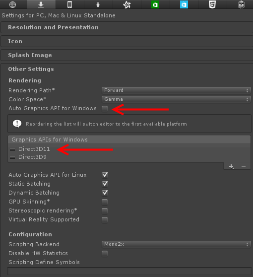
将【Player Settings->Inspector->Other Settings->Use Direct3D 11】选为Direct3D11
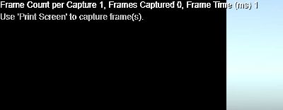
然后点击菜单【Build->Build Solution】,编译完成之后,选择菜单【Go to Debug->Graphics->Start Diagnostics】。这时左上角会提示“Frames captured: 0. Use Print Screen key to capture a frame”的消息,如下图:
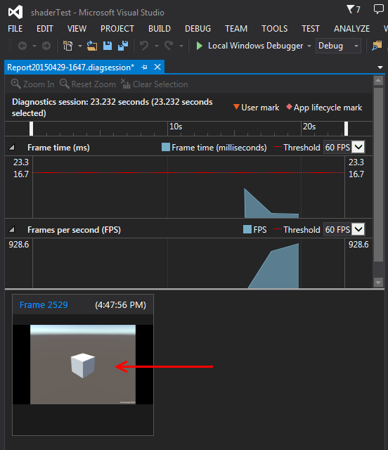
按下“Print Screen”键,然后切换回Visual studio。你就可以看到当前捕获的帧的画面,双击这画面,便可以打开一个新的Visual Studio窗口,如下图:
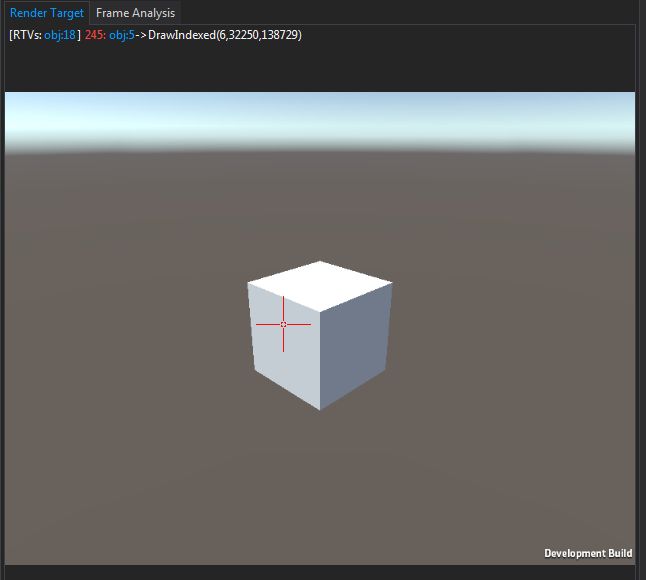
在这个新打开的Visual Studio窗口上,你可以通过鼠标滚轮放大或者缩小这个捕获的帧的大小。把十字叉丝放置到你感兴趣的那个像素点上,然后点击鼠标左键。如下图:
移动鼠标到图形事件列表窗口(Graphics Event List Window)。选择第一个出现的(在事件列表树状控件中最靠顶的那个)"obj:x DrawIndexed"事件。如果VS弹出“No source available”警告。则选择一个在Camera.Render树状控件的项,如下图:
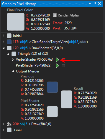
移动到Graphics Pixel History window,在树状控件中,选中【Go to Graphics Pixel History window->obj:x DrawIndexed->Triangle->Vertex Shader】项,然后点击绿色的箭头,如下图:

原文参考的地址:
https://en.wikibooks.org/wiki/Cg_Programming/Unity/Debugging_of_Shaders
http://forum.unity3d.com/threads/debugging-shaders-in-visual-studio.322186/
