ZYBOZ7从入门到进阶-5 一zyboz7实现PS-PL端的交互:ps端+pl端开关控制LED
版权声明:本文为博主原创文章,未经博主允许不得转载。https://blog.csdn.net/a646123070
上篇文章我们进行了交叉编译环境的搭建,写完博客后,才意识到PS+PL端的交互实验还没有写。所以,这篇文章就就是实现PS-PL端的交互:ps端+pl端开关控制LED。
Zynq是以PS端的ARM处理器系统为核心的,PS端和PL端是通过AXI总线,并且Xilinx已经提供了各种AXI通信的IP核,接下来的实验中将会更加明确的体验到利用IP核设计的设计方法。
第一步,先参考ZYBOZ7从入门到进阶-3 zyboz7裸机实现Hello World 博客的方法新建一个空的工程。参考到“添加处理器zynq-7000(IP)内核中的点击图上浅绿色条带中的Run Block Automation,勾选apply board preset,将这个IP核相关的输入/输出信号映射到芯片具体的引脚上,并添加必要的约束。点击OK按钮后启动自动化”这一步。图片如下:
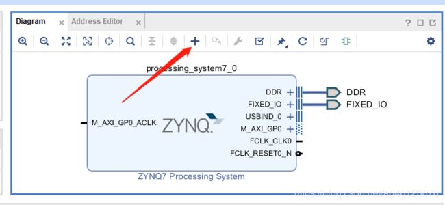
第二步,按照添加内核的方法,我们添加gpio。
首先点击“ADD IP”按钮,在弹出的查找框输入“gpio”,然后双击搜索到的ip,即可完成添加。
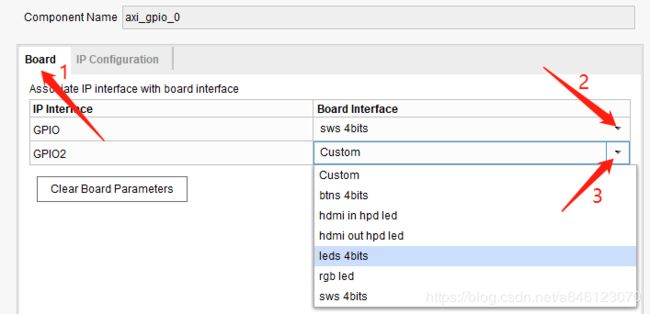
添加完成之后,我们双击GPIO模块(gpio模块变橙色),按照以下两张图片修改内部配置。
第一张图片先选择IP Configuration,然后再按图片上的操作。
第二张图先选择board,然后GPIO、GPIO2分别选择sws 4bits、leds 4bits。 都完成之后点击下方的ok,完成内部配置。
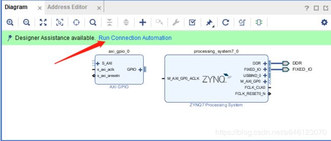
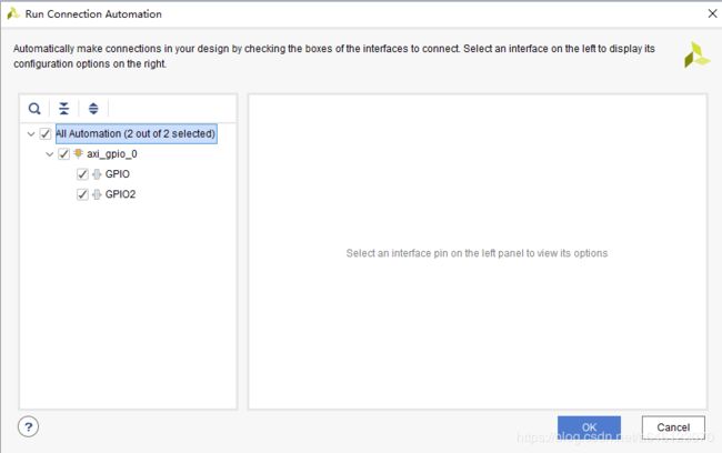
完成后,我们再次点击绿色的Run Connection Automation,进行自动布线。
布线完成之后如下图所示:
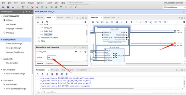
接着,我们点击sws_4bits端口,在External Interface Properties窗口中重命名为sw
同理,把leds_4bits的名称也改为led。
上述流程完成之后,我们按F6进行规则检查。检查没有错误之后,我们添加约束文件。(添加约束文件的方法请参考ZYBOZ7从入门到进阶-2 zyboz7纯PL开发之LED点灯)
把以下代码复制粘贴到约束文件中即可。
#switchsignals
set_property PACKAGE_PIN G15 [get_ports {sw_tri_i[0]}]
set_property IOSTANDARD LVCMOS33 [get_ports {sw_tri_i[0]}]
set_property PACKAGE_PIN P15 [get_ports {sw_tri_i[1]}]
set_property IOSTANDARD LVCMOS33 [get_ports {sw_tri_i[1]}]
set_property PACKAGE_PIN W13 [get_ports {sw_tri_i[2]}]
set_property IOSTANDARD LVCMOS33 [get_ports {sw_tri_i[2]}]
set_property PACKAGE_PIN T16 [get_ports {sw_tri_i[3]}]
set_property IOSTANDARD LVCMOS33 [get_ports {sw_tri_i[3]}]

#ledsignals
set_property PACKAGE_PIN M14 [get_ports {led_tri_o[0]}]
set_property IOSTANDARD LVCMOS33 [get_ports {led_tri_o[0]}]
set_property PACKAGE_PIN M15 [get_ports {led_tri_o[1]}]
set_property IOSTANDARD LVCMOS33 [get_ports {led_tri_o[1]}]
set_property PACKAGE_PIN G14 [get_ports {led_tri_o[2]}]
set_property IOSTANDARD LVCMOS33 [get_ports {led_tri_o[2]}]
set_property PACKAGE_PIN D18 [get_ports {led_tri_o[3]}]
set_property IOSTANDARD LVCMOS33[get_ports {led_tri_o[3]}]
set_property SEVERITY {Warning} [get_drc_checks NSTD-1]
set_property SEVERITY {Warning} [get_drc_checks UCIO-1]
完成之后点击保存,然后综合、实现、生成比特流文件、导出到硬件、打开sdk。(参考ZYBOZ7从入门到进阶-2 zyboz7纯PL开发之LED点灯)
打开SDK后,我们新建一个空的应用。(参考ZYBOZ7从入门到进阶-3 zyboz7裸机实现Hello World)
然后再左侧的工程浏览器找到新建文件夹下的src文件夹中的xxx.c文件,复制粘贴以下代码
/******************************************************************************
*
* Copyright (C) 2009 - 2014 Xilinx, Inc.  All rights reserved.
*
* Permission is hereby granted, free of charge, to any person obtaining a copy
* of this software and associated documentation files (the "Software"), to deal
* in the Software without restriction, including without limitation the rights
* to use, copy, modify, merge, publish, distribute, sublicense, and/or sell
* copies of the Software, and to permit persons to whom the Software is
* furnished to do so, subject to the following conditions:
*
* The above copyright notice and this permission notice shall be included in
* all copies or substantial portions of the Software.
*
* Use of the Software is limited solely to applications:
* (a) running on a Xilinx device, or
* (b) that interact with a Xilinx device through a bus or interconnect.
*
* THE SOFTWARE IS PROVIDED "AS IS", WITHOUT WARRANTY OF ANY KIND, EXPRESS OR
* IMPLIED, INCLUDING BUT NOT LIMITED TO THE WARRANTIES OF MERCHANTABILITY,
* FITNESS FOR A PARTICULAR PURPOSE AND NONINFRINGEMENT. IN NO EVENT SHALL
* XILINX  BE LIABLE FOR ANY CLAIM, DAMAGES OR OTHER LIABILITY,
* WHETHER IN AN ACTION OF CONTRACT, TORT OR OTHERWISE, ARISING FROM, OUT OF
* OR IN CONNECTION WITH THE SOFTWARE OR THE USE OR OTHER DEALINGS IN THE
* SOFTWARE.
*
* Except as contained in this notice, the name of the Xilinx shall not be used
* in advertising or otherwise to promote the sale, use or other dealings in
* this Software without prior written authorization from Xilinx.
*
******************************************************************************/

/*
 * helloworld.c: simple test application
 *
 * This application configures UART 16550 to baud rate 9600.
 * PS7 UART (Zynq) is not initialized by this application, since
 * bootrom/bsp configures it to baud rate 115200
 *
 * ------------------------------------------------
 * | UART TYPE   BAUD RATE                        |
 * ------------------------------------------------
 *   uartns550   9600
 *   uartlite    Configurable only in HW design
 *   ps7_uart    115200 (configured by bootrom/bsp)
 */

#include
#include "platform.h"
#include "xgpio.h"

XGpio SW_LED;
#define SW_CHANNEL 1
#define LED_CHANNEL 2
#define SW_IN XGpio_SetDataDirection(&SW_LED, SW_CHANNEL, 0x0f)
#define LED_OUT XGpio_SetDataDirection(&SW_LED, LED_CHANNEL, 0x00)
#define SW_VALUE XGpio_DiscreteRead(&SW_LED, SW_CHANNEL)

int init_gpio()
{
 int Status;
    /*
    *Initialize the IIC GPIO
    */
    Status= XGpio_Initialize(&SW_LED, XPAR_AXI_GPIO_0_DEVICE_ID);
    if (Status != XST_SUCCESS){

    return XST_FAILURE;
    }
    SW_IN;
    LED_OUT;
    return XST_SUCCESS;
}
int main()
{
   init_platform();

   init_gpio();

   printf("Successfully ran Gpio Example\n");
   int value;
   while(1)
   {
    value = SW_VALUE;
    XGpio_DiscreteWrite(&SW_LED, LED_CHANNEL,value);
   }

   cleanup_platform();
   return 0;
}
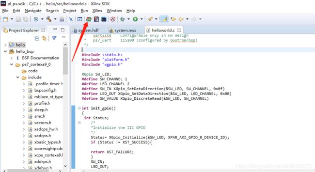
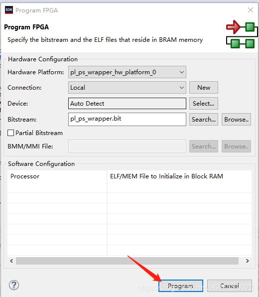
完成之后点击保存。接着我们下载到开发板(开发板选择jtag启动)。首先打开开发板,使用串口工具连接,然后点击sdk软件中的program FPGA,之后在弹出的页面点击program。
完成之后,开发板上的ld12灯会亮起,代表下载完成。然后我们运行程序。(点击sdk软件中的run--->run as --->launch on hardware),然后再弹出的页面点击run,接着,串口会打印出Successfully ran Gpio Example,同时我们也可以使用sw0~3控制led0~3。这样我们的教程就结束了。
最后想说,如果操作步骤有不详细的,可以参考我之前写的ZYBOZ7从入门到进阶系列的文章。有不明白的可以在下边留言。

