FPGA实现图像Sobel边沿检测
FPGA实现图像Sobel边沿检测
梯度算子
一幅数字图像的一阶导数是基于各种二维梯度的近似值。图像发f(x,y)在位置(x,y)的梯度定义为下列向量:
∇ f = [ G x G y ] = [ ∂ f ∂ x ∂ f ∂ y ] \nabla f=\begin{bmatrix} G{x} \\ G{y} \end{bmatrix}=\begin{bmatrix} \frac{\partial f}{\partial x} \\ \\ \frac{\partial f}{\partial y} \end{bmatrix} ∇f=[GxGy]=⎣⎡∂x∂f∂y∂f⎦⎤
从向量分析中可知,梯度向量指向在坐标(x,y)的f的最大变化率方向。
在边沿检测中,一个重要的量是这个向量的大小,用▽f表示,
∇ f = m a g ( ∇ f ) = [ G x 2 + G y 2 ] 1 2 \nabla f=mag(\nabla f)={\begin{bmatrix} G_x^2+G_y^2 \end{bmatrix}}^\frac{1}{2} ∇f=mag(∇f)=[Gx2+Gy2]21
这个量给出了在▽f方向上每增加单位距离后f(x,y)值增大的最大变化率。一般来讲也将▽f称为梯度。
梯度向量的方向也是一个重要的量。令α(x,y)表示向量▽f在(x,y)处的方位角。然后由向量分析得到:
α ( x , y ) = a r c t a n ( G y G x ) α(x,y)=arctan(\frac{G_y}{G_x}) α(x,y)=arctan(GxGy)
其中,角度是以x轴为基准量度的。边缘在(x,y)处的方向与此点的梯度向量的方向垂直。
Sobel算子
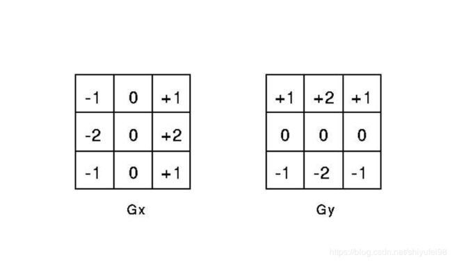
Sobel算子的公式为
G x = ( z 7 + 2 z 8 + z 9 ) − ( z 1 + 2 z 2 + z 3 ) G y = ( z 3 + 2 z 6 + z 9 ) − ( z 1 + 2 z 4 + z 7 ) G_x=(z_7+2z_8+z_9)-(z_1+2z_2+z_3)\\ G_y=(z_3+2z_6+z_9)-(z_1+2z_4+z_7)\\ Gx=(z7+2z8+z9)−(z1+2z2+z3)Gy=(z3+2z6+z9)−(z1+2z4+z7)
权值的2用于增加中心点的重要性而实现某种程度的平滑效果。因为计算平方和和平方根需要大量的计算,经常使用绝对值对梯度进行近似:
∇ f = ∣ G x ∣ + ∣ G y ∣ \nabla f=|G_x|+|G_y| ∇f=∣Gx∣+∣Gy∣

Sobel边缘检测的核心在于像素矩阵的卷积,卷积对于数字图像处理非常重要,很多图像处理算法都是做卷积来实现。卷积运算的本质就是对制定的图像区域的像素值进行加权求和的过程,其计算过程为图像区域的每一个像素值分别与卷积模版的每个元素对应相乘,将卷积的结果作为去和运算,运算到的和就是卷积的结果。
Matlab仿真
%RGB_YCbCr
clc;
clear all;
close all;

RGB_data = imread('lena.jpg');%

R_data =    RGB_data(:,:,1);
G_data =    RGB_data(:,:,2);
B_data =    RGB_data(:,:,3);

%imshow(RGB_data);

[ROW,COL, DIM] = size(RGB_data);

Y_data = zeros(ROW,COL);
Cb_data = zeros(ROW,COL);
Cr_data = zeros(ROW,COL);
Gray_data = RGB_data;

for r = 1:ROW
    for c = 1:COL
        Y_data(r, c) = 0.299*R_data(r, c) + 0.587*G_data(r, c) + 0.114*B_data(r, c);
        Cb_data(r, c) = -0.172*R_data(r, c) - 0.339*G_data(r, c) + 0.511*B_data(r, c) + 128;
        Cr_data(r, c) = 0.511*R_data(r, c) - 0.428*G_data(r, c) - 0.083*B_data(r, c) + 128;
    end
end

Gray_data(:,:,1)=Y_data;
Gray_data(:,:,2)=Y_data;
Gray_data(:,:,3)=Y_data;

figure;
imshow(Gray_data);

%Median Filter
imgn = imnoise(Gray_data,'salt & pepper',0.02);

figure;
imshow(imgn);

Median_Img = Gray_data;
for r = 2:ROW-1
    for c = 2:COL-1
        median3x3 =[imgn(r-1,c-1)    imgn(r-1,c) imgn(r-1,c+1)
                    imgn(r,c-1)      imgn(r,c)      imgn(r,c+1)
                    imgn(r+1,c-1)      imgn(r+1,c) imgn(r+1,c+1)];
        sort1 = sort(median3x3, 2, 'descend');
        sort2 = sort([sort1(1), sort1(4), sort1(7)], 'descend');
        sort3 = sort([sort1(2), sort1(5), sort1(8)], 'descend');
        sort4 = sort([sort1(3), sort1(6), sort1(9)], 'descend');
        mid_num = sort([sort2(3), sort3(2), sort4(1)], 'descend');
        Median_Img(r,c) = mid_num(2);
    end
end

figure;
imshow(Median_Img);

%Sobel_Edge_Detect

Median_Img = double(Median_Img);
Sobel_Threshold = 150;
Sobel_Img = zeros(ROW,COL);
for r = 2:ROW-1
    for c = 2:COL-1
        Sobel_x = Median_Img(r-1,c+1) + 2*Median_Img(r,c+1) + Median_Img(r+1,c+1) - Median_Img(r-1,c-1) - 2*Median_Img(r,c-1) - Median_Img(r+1,c-1);
        Sobel_y = Median_Img(r-1,c-1) + 2*Median_Img(r-1,c) + Median_Img(r-1,c+1) - Median_Img(r+1,c-1) - 2*Median_Img(r+1,c) - Median_Img(r+1,c+1);
        Sobel_Num = abs(Sobel_x) + abs(Sobel_y);
        %Sobel_Num = sqrt(Sobel_x^2 + Sobel_y^2);
        if(Sobel_Num > Sobel_Threshold)
            Sobel_Img(r,c)=0;
        else
            Sobel_Img(r,c)=255;
        end
    end
end

figure;
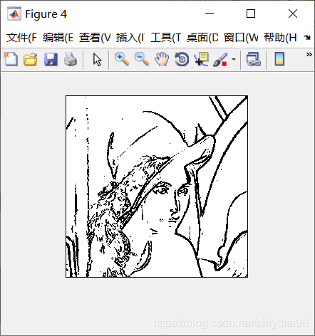
imshow(Sobel_Img);
FPGA实现Sobel算子
为了实现 FPGA 的加速运算, 发挥并行流水线的特性,可以划分为 4 个步骤, 解析与实现分别如下:
(1) 计算计算 Gx与 Gy与模板每行的乘积
(2) 求得 3*3 模板运算后的 Gx、 Gy
//Sobel Parameter
//         Gx                  Gy				  Pixel
// [   -1  0   +1  ]   [   +1  +2   +1 ]     [   P11  P12   P13 ]
// [   -2  0   +2  ]   [   0   0    0  ]     [   P21  P22   P23 ]
// [   -1  0   +1  ]   [   -1  -2   -1 ]     [   P31  P32   P33 ]

// localparam	P11 = 8'd15,	P12 = 8'd94,	P13 = 8'd136;
// localparam	P21 = 8'd31,	P22 = 8'd127,	P23 = 8'd231;
// localparam	P31 = 8'd44,	P32 = 8'd181,	P33 = 8'd249;
//Caculate horizontal Grade with |abs|
//Step 1-2
reg	[9:0]	Gx_temp1;	//postive result
reg	[9:0]	Gx_temp2;	//negetive result
reg	[9:0]	Gx_data;	//Horizontal grade data
always@(posedge clk or negedge rst_n)
begin
	if(!rst_n)
		begin
		Gx_temp1 <= 0;
		Gx_temp2 <= 0;
		Gx_data <= 0;
		end
	else
		begin
		Gx_temp1 <= matrix_p13 + (matrix_p23 << 1) + matrix_p33;	//postive result
		Gx_temp2 <= matrix_p11 + (matrix_p21 << 1) + matrix_p31;	//negetive result
		Gx_data <= (Gx_temp1 >= Gx_temp2) ? Gx_temp1 - Gx_temp2 : Gx_temp2 - Gx_temp1;
		end
end

//---------------------------------------
//Caculate vertical Grade with |abs|
//Step 1-2
reg	[9:0]	Gy_temp1;	//postive result
reg	[9:0]	Gy_temp2;	//negetive result
reg	[9:0]	Gy_data;	//Vertical grade data
always@(posedge clk or negedge rst_n)
begin
	if(!rst_n)
		begin
		Gy_temp1 <= 0;
		Gy_temp2 <= 0;
		Gy_data <= 0;
		end
	else
		begin
		Gy_temp1 <= matrix_p11 + (matrix_p12 << 1) + matrix_p13;	//postive result
		Gy_temp2 <= matrix_p31 + (matrix_p32 << 1) + matrix_p33;	//negetive result
		Gy_data <= (Gy_temp1 >= Gy_temp2) ? Gy_temp1 - Gy_temp2 : Gy_temp2 - Gy_temp1;
		end
end
(3) 求得 Gx2+Gy2 的结果, 及 Gx 与 Gy 的平方和
//Caculate the square of distance = (Gx^2 + Gy^2)
//Step 3
reg	[20:0]	Gxy_square;
always@(posedge clk or negedge rst_n)
begin
	if(!rst_n)
		Gxy_square <= 0;
	else
		Gxy_square <= Gx_data * Gx_data + Gy_data * Gy_data;
end
//Caculate the distance of P5 = (Gx^2 + Gy^2)^0.5
//Step 4
wire	[10:0]	Dim;
SQRT	u_SQRT
(
	.radical	(Gxy_square),
	.q			(Dim),
	.remainder	()
);
( 5) 根据外部输入阀值,判断并实现边缘的检测
简单的判断 Dim 的大小而已,大于阀值,视为有效,赋 1; 反之则赋 0。
//Compare and get the Sobel_data
//Step 5
reg [15:0]	post_img_Bit_r;
always@(posedge clk or negedge rst_n)
begin
	if(!rst_n)
		post_img_Bit_r <= 16'd0;	//Default None
	else if(Dim >= Sobel_Threshold)
		post_img_Bit_r <= 16'hffff;	//Edge Flag
	else
		post_img_Bit_r <= 16'd0;	//Not Edge
end

//always @(posedge clk or negedge rst_n)
//------------------------------------------
//lag 5 clocks signal sync
reg	[4:0]	per_frame_vsync_r;
reg	[4:0]	per_frame_href_r;
reg	[4:0]	per_frame_clken_r;
always@(posedge clk or negedge rst_n)
begin
	if(!rst_n)
		begin
		per_frame_vsync_r <= 0;
		per_frame_href_r <= 0;
		per_frame_clken_r <= 0;
		end
	else
		begin
		per_frame_vsync_r 	<= 	{per_frame_vsync_r[3:0], 	matrix_frame_vsync};
		per_frame_href_r 	<= 	{per_frame_href_r[3:0], 	matrix_frame_href};
		per_frame_clken_r 	<= 	{per_frame_clken_r[3:0], 	matrix_frame_clken};
		end
end
assign	post_frame_vsync 	= 	per_frame_vsync_r[4];
assign	post_frame_href 	= 	per_frame_href_r[4];
assign	post_frame_clken 	= 	per_frame_clken_r[4];
assign	post_img_Bit		=	post_frame_href ? post_img_Bit_r :16'd0;
本文引用了其他文章资料,如有侵权,联系本人会做出修改。版本1.0,2019.11.05 作者小飞。


