CMOS摄像头驱动分析笔记1
最近学习摄像头驱动,刚刚大体上看完,有些地方换是不太明白,先做个笔记总结一下这几天看的,水平不行,语言很搓,有错误欢迎指正,十分感谢。
CMOS摄像头接口
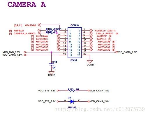
接口主要由I2C控制总线部分和摄像头数据传输部分组成,i2c控制部分主要完成对摄像头模块的初始化,初始化后摄像头才能工作,
摄像头数据传输接口叫做CAMIF接口,也叫FIMC,之前关于这个FIMC是什么一直不懂,最后才知道,它就是摄像头接口,有硬件接口,可以直接连摄像头,也可以用做视频数据颜色空间的转换,
先从OV5642的驱动程序开始看吧,
static struct i2c_driver ov5642_i2c_driver = {
	.driver = {
		.name = "ov5642",
	},
	.probe		= ov5642_probe,
	.remove		= ov5642_remove,
	.id_table	= ov5642_id,
};

module_i2c_driver(ov5642_i2c_driver);
定义了ov5642的i2c驱动,module_i2c_driver为加载驱动,让系统中有注册OV5642的I2C设备时,会进行驱动与设备的匹配,匹配成功则执行驱动中的probe函数,
static const struct i2c_device_id ov5642_id[] = {
	{ "ov5642", 0 },
	{ }
};
MODULE_DEVICE_TABLE(i2c, ov5642_id);
定义了设备ID表,说明了这个驱动支持那些设备,这个驱动里只有一项,名字叫ov5642的设备,
然后假设现在系统里有注册名为OV5642的设备,则与驱动程序匹配成功,执行probe函数,
static int ov5642_probe(struct i2c_client *client,
			const struct i2c_device_id *did)
{ struct ov5642 *priv;
struct v4l2_subdev *sd;//add
struct soc_camera_link *icl = soc_camera_i2c_to_link(client);
int ret;
if (!icl) {
dev_err(&client->dev, "OV5642: missing platform data!\n");
return -EINVAL;
}
priv = kzalloc(sizeof(struct ov5642), GFP_KERNEL);
if (!priv)
return -ENOMEM;
sd=&priv->subdev;//add上面为probe函数刚开始的部分,
刚开始要定义一些结构,OV5642结构,v4l2_subdev结构,
struct ov5642 {
	struct v4l2_subdev		subdev;
	const struct ov5642_datafmt	*fmt;
	struct v4l2_rect                crop_rect;
	struct media_pad pad;

	/* blanking information */
	int total_width;
	int total_height;
};priv = kzalloc(sizeof(struct ov5642), GFP_KERNEL);为struct ov5642分配内存 sd=&priv->subdev;//add把subdev结构取出来,赋给变量sd
v4l2_i2c_subdev_init(&priv->subdev, client, &ov5642_subdev_ops);这个函数里主要做的是初始化subdev的操作函数,然后把client和subdev相互关联,以后通过client可以访问到subdev,通过subdev也可以访问到client,
void v4l2_i2c_subdev_init(struct v4l2_subdev *sd, struct i2c_client *client,
		const struct v4l2_subdev_ops *ops)
{
	v4l2_subdev_init(sd, ops);//这个函数很关键,初始化了subdev的操作函数,
	sd->flags |= V4L2_SUBDEV_FL_IS_I2C;
	/* the owner is the same as the i2c_client's driver owner */
	sd->owner = client->driver->driver.owner;
	/* i2c_client and v4l2_subdev point to one another */
	v4l2_set_subdevdata(sd, client);//设置subdevdata为client
	i2c_set_clientdata(client, sd);//设置clientdata为subdevdata
	/* initialize name */
	snprintf(sd->name, sizeof(sd->name), "%s %d-%04x",
		client->driver->driver.name, i2c_adapter_id(client->adapter),
		client->addr);
}
EXPORT_SYMBOL_GPL(v4l2_i2c_subdev_init);
然后
priv->pad.flags=MEDIA_PAD_FL_SOURCE;//addsd->entity.type=MEDIA_ENT_T_V4L2_SUBDEV_SENSOR;//add
ret=media_entity_init(&sd->entity, 1, &priv->pad, 0);//add,初始化多媒体实体,具体多媒体指什么,我还不懂??
if(ret)//add
		goto error;//add
	priv->fmt		= &ov5642_colour_fmts[0];

	priv->crop_rect.width	= OV5642_DEFAULT_WIDTH;
	priv->crop_rect.height	= OV5642_DEFAULT_HEIGHT;
	priv->crop_rect.left	= (OV5642_MAX_WIDTH - OV5642_DEFAULT_WIDTH) / 2;
	priv->crop_rect.top	= (OV5642_MAX_HEIGHT - OV5642_DEFAULT_HEIGHT) / 2;
	priv->total_width = OV5642_DEFAULT_WIDTH*2 + BLANKING_EXTRA_WIDTH;
	priv->total_height = BLANKING_MIN_HEIGHT;
初始化结构,
ret = ov5642_video_probe(client);这个函数里主要做的是初始化了ov5642芯片,
static int ov5642_video_probe(struct i2c_client *client)
{
	struct v4l2_subdev *subdev = i2c_get_clientdata(client);
	int ret;
	u8 id_high, id_low;
	u16 id;
       // unsigned int i;
	ret = ov5642_s_power(subdev, 1);
	if (ret < 0)
		return ret;
	/* Read sensor Model ID */
		ret = reg_read(client, REG_CHIP_ID_HIGH, &id_high);
		if (ret < 0)
		goto done;
		id = id_high << 8;

		ret = reg_read(client, REG_CHIP_ID_LOW, &id_low);
		if (ret < 0)
			goto done;
		id |= id_low;

	if (id != 0x5642) {
		ret = -ENODEV;
		goto done;
	}
	ret = 0;

done:
	ov5642_s_power(subdev, 0);
	return ret;
}
static int ov5642_s_power(struct v4l2_subdev *sd, int on)
{
struct i2c_client *client = v4l2_get_subdevdata(sd);从SD结构得到client
struct soc_camera_link *icl = soc_camera_i2c_to_link(client);
int ret;
if (!on)
return soc_camera_power_off(&client->dev, icl);
ret = soc_camera_power_on(&client->dev, icl);
if (ret < 0)
return ret;
ret = ov5642_write_array(client, ov5642_default_regs_init);初始化硬件,通过i2c总线,
//if (!ret)
//ret = ov5642_set_resolution(sd);
if (!ret)
ret = ov5642_write_array(client, ov5642_default_regs_finalise);
return ret;
}static int ov5642_write_array(struct i2c_client *client,
struct regval_list *vals)
{
while (vals->reg_num != 0xffff || vals->value != 0xff) {
int ret = reg_write(client, vals->reg_num, vals->value);
if (ret < 0)
return ret;
vals++;
}
dev_dbg(&client->dev, "Register list loaded\n");
return 0;
}ov5642的初始化数组,static struct regval_list ov5642_default_regs_init[] = {.......},前面定义过的,数组里的内容芯片厂家提供,我们按这个默认的配置数组初始化就行,
这个函数就分析到这,他主要做的就是初始化了硬件OV5642然后初始化了subdev结构,这样的话后面通过I2C_CLIENT又可以访问到subdev结构,
然后看一下我的开发板的关于摄像头的板级配置信息吧
摄像头驱动由两部分组成,一部分为上面的i2c控制部分组成,另一部分由摄像头数据接口部分也叫FIMC部分组成,他们两个组合起来就是完整的摄像头驱动,他们直接怎么联系起来的呢,请看板级配置信息
#define CAMA_PWR_EN		S5PV210_GPJ2(6)
static int ov5642_power_en(struct device *dev ,int onoff) {
	int ret;

	ret = gpio_request(CAMA_PWR_EN, "GPJ2_6");
	if (ret) {
		printk("request GPJ2_6 failed for camera power, %d\n", ret);
	}

	gpio_direction_output(CAMA_PWR_EN, !onoff);
	gpio_free(CAMA_PWR_EN);

	printk("ov5642: power %s\n", onoff ? "ON" : "Off");
	return 0;
}
static struct soc_camera_link ov5642_platdata={
.bus_id = 0,
.i2c_adapter_id = 0,
.power = ov5642_power_en,
};static struct i2c_board_info s5p_i2c_info __initdata = {
I2C_BOARD_INFO("ov5642", 0x3c),
.platform_data=&ov5642_platdata
};static struct s5p_fimc_isp_info mini210s_fimc_info[]={
[0] ={
.mux_id=0,//senser [0]
.i2c_bus_num=0,//i2c0
.clk_frequency=96000000UL, 读取数据频率
.bus_type =FIMC_ITU_601, 数据传输方式
.board_info=&s5p_i2c_info,
.flags = V4L2_MBUS_PCLK_SAMPLE_RISING|V4L2_MBUS_HSYNC_ACTIVE_HIGH,
.clk_id=0,//camclk0
},
};static struct s5p_platform_fimc fimc_md_platdata={
.isp_info=mini210s_fimc_info,
.num_clients=ARRAY_SIZE(mini210s_fimc_info),
};通过上面的一些结构把fimc,i2c,ov5642的特性等联系了起来
static struct platform_device *smdkv210_devices[] __initdata = {
	&s3c_device_adc,
	&s3c_device_1wire,
	&s3c_device_nand,
&s5p_device_fimc0, &s5p_device_fimc_md, ..............板级设备初始化数组
static struct resource s5p_fimc0_resource[] = {
	[0] = DEFINE_RES_MEM(S5P_PA_FIMC0, SZ_4K),
	[1] = DEFINE_RES_IRQ(IRQ_FIMC0),
};

struct platform_device s5p_device_fimc0 = {
	.name		= "s5pv210-fimc",
	.id		= 0,
	.num_resources	= ARRAY_SIZE(s5p_fimc0_resource),
	.resource	= s5p_fimc0_resource,
	.dev		= {
		.dma_mask		= &samsung_device_dma_mask,
		.coherent_dma_mask	= DMA_BIT_MASK(32),
	},
};

struct platform_device s5p_device_fimc_md = {
	.name	= "s5p-fimc-md",
	.id	= -1,
};
上面是关于fimc的板级信息,其中fimc_md相当于管理所有fimc的一个结构,在以前的内核版本里没有它,
static void __init smdkv210_machine_init(void),关键的函数,设备初始化注册函数
  mdelay(10);
	gpio_request(S5PV210_GPJ2(6), "GPJ2_6");//pwdn
	gpio_direction_output(S5PV210_GPJ2(6), 0);

        gpio_request(S5PV210_GPJ3(1), "GPJ3_1");//reset
	gpio_direction_output(S5PV210_GPJ3(1), 0);
        mdelay(100);
        gpio_request(S5PV210_GPJ3(1), "GPJ3_1");//reset
	gpio_direction_output(S5PV210_GPJ3(1), 1);
        mdelay(40);
	gpio_free(S5PV210_GPJ2(6));
	gpio_free(S5PV210_GPJ3(1));//上面为硬件复位摄像头模块
/***************************************************************************/
        s3c_set_platdata(& fimc_md_platdata,  sizeof( fimc_md_platdata),
			 &s5p_device_fimc_md);//add将fimc_md_platdata结构加入到平台设备s5p_device_fimc_md结构中
	 s5pv210_fimc_setup_gpio(S5P_CAMPORT_A);//选择摄像头接口为cameraA,总共有两个,一个是A一个是B,这个开发板上使用的是A
platform_add_devices(smdkv210_devices, ARRAY_SIZE(smdkv210_devices));