MPLS总部分部共用AS架构案例
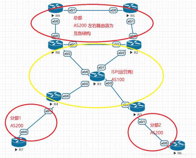
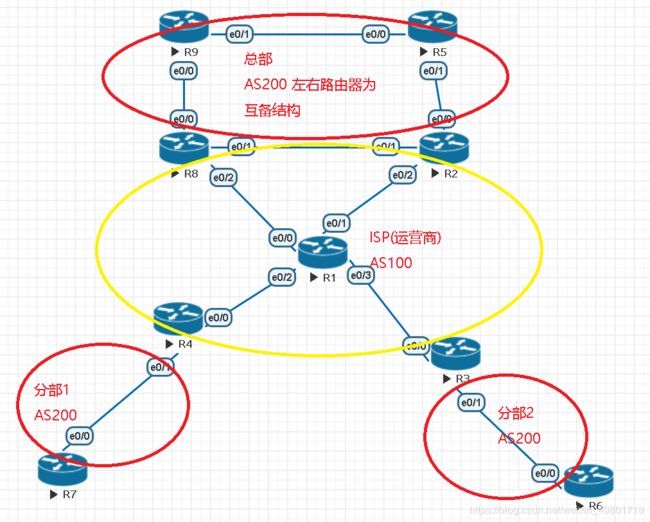
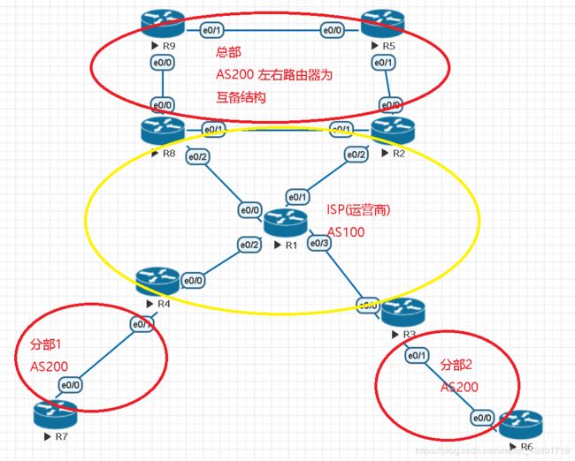
架构如图
情景描述1:
某大型企业因为一些原因,ISP(运营商)只给该企业分配了一个为200的AS,其需要将该200的AS同时运用在总部和两个分部内,该架构中间为ISP的AS100.正常要是两个分部之间互通,需要在其间拉上一条专线。该企业为了省下成本,让两个分部之间通信时要先走总部,经过总部再到另一个分部。
情景分析:
需要经过总部中转,该总部的路由器需要逻辑的分为两个路由器,一个用来收路由,一个用来转发路由。
解决与配置:
1.中间ISP运行VPNV4-BGP(前提先运行动态路由协议,这里选用eigrp)
- R1上
 //设置bgp
 router bgp 100
 bgp router-id 1.1.1.1
 // 关闭默认ipv4单播
 no bgp default ipv4-unicast
 neighbor IBGP peer-group
 neighbor IBGP remote-as 100
 neighbor IBGP update-source Loopback0
 neighbor 10.2.2.2 peer-group IBGP
 neighbor 10.3.3.3 peer-group IBGP
 neighbor 10.4.4.4 peer-group IBGP
 neighbor 10.8.8.8 peer-group IBGP
 //设置v4-bgp
 address-family v4
 neighbor IBGP send-community extended
 neighbor IBGP route-reflector-client
 neighbor 10.2.2.2 activate
 neighbor 10.3.3.3 activate
 neighbor 10.4.4.4 activate
 neighbor 10.8.8.8 activate
- R2 R3 R4 R8上
 //设置bgp
 router bgp 100
 bgp router-id 2.2.2.2
 //关闭ipv4的单播
 no bgp default ipv4-unicast
 neighbor 10.1.1.1 remote-as 100
 neighbor 10.1.1.1 update-source Loopback0
 //设置v4-bgp
 address-family v4
 neighbor 10.1.1.1 activate
 neighbor 10.1.1.1 send-community extended
2.企业边界路由器配置VRF,逻辑的将该路由器分为收和转发路由的两台虚拟路由器
- R8劈子接口(R2一样)
 interface ethernet0/0
 no shutdown //先进入未划分接口,将接口no shutdown
 interface ethernet0/0.1
 encapsulation dot1Q 1 //修改封装,数字值两端子接口须一致
 ip address 10.100.89.8 255.255.255.0
 interface ethernet0/0.2
 encapsulation dot1Q 2 //修改封装,数字值两端子接口须一致
 ip address 10.200.89.8 255.255.255.0
- vrf(to_hub)- - -收路由
 ip vrf to_hub //设置vrf名为to_hub
 rd 8:9 //设置rd值为8:9
 route-target import 200:3 //设置收到的rt值为200:3
 route-target import 200:4 //设置收到的rt值为200:4
- vrf(to_spoke)- - -发路由
 ip vrf to_spoke //设置vrf名为to_spoke
 rd 9:8 //设置rd值为9:8
 route-target export 200:8 //设置发出的rt值为200:8
- 将不同的vrf划分到不同的子接口
 interface ethernet0/0.1
 ip vrf forwarding to_hub //将to_hub划分到子接口e0/0.1中
 ip address 10.100.89.8 255.255.255.0
 interface ethernet0/0.2
 ip vrf forwarding to_spoke //将to_spoke划分到子接口e0/0.2中
 ip address 10.200.89.8 255.255.255.0
3.总部内建立IBGP邻居
- R9上(R5上同理)
 router ospf 1 //底层运行动态路由协议,此处为ospf
 router-id 9.9.9.9
 network 10.9.9.9 0.0.0.0 area 0
 network 10.59.1.0 0.0.0.255 area 0

 router bgp 200 //启用AS号为200的BGP
 bgp router-id 9.9.9.9
 neighbor 10.5.5.5 remote-as 200 //与R5建立IBGP邻居
 neighbor 10.5.5.5 update-source Loopback0 //修改本地更新源为环回0
 neighbor 10.5.5.5 next-hop-self //修改下一跳为本地
4.总部和运营商之间建立EBGP邻居
- 运营商- -R8上(R2同理)
 router bgp 100
 address-family ipv4 vrf to_hub //vrf to_hub中设置ebgp邻居
 neighbor 10.100.89.9 remote-as 200
 neighbor 10.100.89.9 activate
 address-family ipv4 vrf to_spoke ////vrf to_spoke中设置ebgp邻居
 neighbor 10.200.89.9 remote-as 200
 neighbor 10.200.89.9 activate
- 总部- -R9上(R2同理)
 router bgp 200 //启用AS号为200的BGP
 bgp router-id 9.9.9.9
 network 10.9.9.9 mask 255.255.255.255 //BGP中宣告环回10.9.9.9
 neighbor 10.100.89.8 remote-as 100 //和对端子接口1建立EBGP邻居
 neighbor 10.200.89.8 remote-as 100 //和对端子接口2建立EBGP邻居
5.运营商和分部之间
R4上启用vrf(R3上同理)
 ip vrf spoke1 //设置vrf名为spoke1
 rd 4:7 //rd值为4:7
 route-target export 200:4 //rd发出的值为200:4
 route-target import 200:2 //rd收到的值为200:2
 route-target import 200:8 //rd收到的值为200:8
运营商和分部建立EBGP邻居
- R4上(R3上同理)
 router bgp 100
 address-family ipv4 vrf spoke1 //vrf spoke1中设置ebgp邻居
 neighbor 10.47.1.7 remote-as 200
 neighbor 10.47.1.7 activate
- R7上(R6上同理)
 router bgp 200 //启用AS号为200的bgp
 bgp router-id 7.7.7.7
 network 10.7.7.7 mask 255.255.255.255
 neighbor 10.47.1.4 remote-as 100
6.R5、R6、R7、R9的BGP分别宣告环回
- R5上
router bgp 200
network 10.5.5.5 mask 255.255.255.255
- R6上
router bgp 200
network 10.6.6.6 mask 255.255.255.255
- R7上
router bgp 200
network 10.7.7.7 mask 255.255.255.255
- R9上
router bgp 200
network 10.9.9.9 mask 255.255.255.255
7.R1 R2 R3 R4 R8开启MPLS
以R1为例
mpls ldp router-id Loopback0 force //用环回作为ldp邻居建立的route-id

interface range e0/0-3 //接口下设置mpls
mpls ip //启用mpls
但是!!!
因为AS-PATH的水平分割,所以同为AS200的分部的BGP路由不能进入AS200的总部,同理,总部的BGP路由也不能到达分部
解决方法:
在运营商与总部相连的边界路由器R8上(R2同理)的to_hub的ipv4 bgp中设置允许携带有本AS的路由进入本AS, 在to_spoke的ipv4 bgp设置可以接收携带本AS的路由.
- R8上(R2上同理)
router bgp 100
address-family ipv4 vrf to_hub
neighbor 10.100.89.9 as-override //允许携带有本AS的路由进入本AS
address-family ipv4 vrf to_spoke
neighbor 10.200.89.9 allowas-in //接收携带本AS的路由
- R4上(R3上同理)
router bgp 100
address-family ipv4 vrf spoke1
neighbor 10.47.1.7 as-override //允许携带有本AS的路由进入本AS
结果:
测试:
情景描述2:
分部1有两类路由
一类为业务流量,在这里假设为10.80.7.7/32;另一类为办公流量,在这里假设为10.90.7.7/32
同理
分部2也有两类路由
一类为业务流量,在这里假设为10.80.6.6/32;另一类为办公流量,在这里假设为10.90.6.6/32
现要求:
前缀为10.80.0.0/16的流量走R8到达总部
前缀为10.90.0.0/16的流量走R2到达总部
使得不同的流量走不同的路到达总部,即达到分流作用
以R7为例
如果在R7上分别对两种流量打上团体标记,比如10.80.7.7/32打上标记200:80 10.90.7.7/32打上标记200:90,但是事实发现该团体标记并不会传给其他bgp邻居,因为rt值也是团体属性,它会使得另外打团体标记会打不上标记。故只能直接匹配流量
1.在R9上使用前缀列表抓取流量
ip prefix-list 80 seq 5 permit 10.80.0.0/16 ge 17 //抓取80的流量
ip prefix-list 90 seq 5 permit 10.90.0.0/16 ge 17 //抓取90的流量
2.使用route-map加大10.80.0.0/16的local-prefence值,并调用在进流量的ebgp邻居处
route-map in permit 10 //定义route-map
match ip address prefix-list 80 //匹配为80的前缀列表
set local-preference 120 //设置local值为120

router bgp 200
neighbor 10.100.89.8 route-map in in  //调用在进流量的ebgp邻居处
3.使用route-map加大10.90.0.0/16的metric值,并调用在出流量的ebgp邻居处。使得10.90.0.0/16的流量走R5,即另一边下去,而不是从本处下去。
route-map out permit 10 //定义route-map
match ip address prefix-list 90 //匹配为90的前缀列表
set metric 100 //设置metric值为100

router bgp 200
neighbor 10.200.89.8 route-map out out //调用在出流量的ebgp邻居处
R5上设置与R9上同理
结果:
效果:
实现了不同流量的分流
情景描述3:
分部的流量访问公网要经过总部
情景分析:
需要经过总部访问公网1.2.3.4/32,就需要在连接总部与公网的路由器上另开启子接口,然后设置nat
解决与配置:
1.R8上开启子接口e0/0.3
interface Ethernet0/0.3
encapsulation dot1Q 3 native
ip address 10.0.89.8 255.255.255.0
2.公网的R1上bgp宣告1.2.3.4/32
router bgp 100
address-family ipv4
network 1.2.3.4 mask 255.255.255.255
3.公网的R8上bgp宣告10.0.89.0- - -为了公网互通
router bgp 100
address-family ipv4
network 10.0.89.0 mask 255.255.255.0
4.总部的R9上下方默认路由
ip route 0.0.0.0 0.0.0.0 10.0.89.8 //指向公网的静态默认

router bgp 200
default-information originate
network 0.0.0.0 //bgp下放默认路由
5.总部的R9上抓取需要nat转换的流量并调用在接口上
access-list 1 permit 10.0.0.0 0.255.255.255  //用acl抓取10.0.0.0/8
ip nat inside source list 1 interface Ethernet0/0.3 overload //接口调用acl进行相应nat转换
6.总部的R9上定义inside和outside
interface Ethernet0/0.2 //流量的进口,也就是to_spoke
ip nat inside
interface Ethernet0/0.3
ip nat outside
interface Ethernet0/1  //e0/1也可能进流量,故也设置为inside口
ip nat inside
结果:
各个路由器配置的running-config
R1
interface Loopback0
ip address 10.1.1.1 255.255.255.255
interface Loopback100
ip address 1.2.3.4 255.255.255.255
interface Ethernet0/0
ip address 10.18.1.1 255.255.255.0
mpls ip
interface Ethernet0/1
ip address 10.12.1.1 255.255.255.0
mpls ip
interface Ethernet0/2
ip address 10.14.1.1 255.255.255.0
mpls ip
interface Ethernet0/3
ip address 10.13.1.1 255.255.255.0
mpls ip
router eigrp 90
network 0.0.0.0
router bgp 100
bgp router-id 1.1.1.1
no bgp default ipv4-unicast
neighbor IBGP peer-group
neighbor IBGP remote-as 100
neighbor IBGP update-source Loopback0
neighbor 10.2.2.2 peer-group IBGP
neighbor 10.3.3.3 peer-group IBGP
neighbor 10.4.4.4 peer-group IBGP
neighbor 10.8.8.8 peer-group IBGP
address-family ipv4
network 1.2.3.4 mask 255.255.255.255
neighbor 10.2.2.2 activate
neighbor 10.3.3.3 activate
neighbor 10.4.4.4 activate
neighbor 10.8.8.8 activate
address-family v4
neighbor IBGP send-community extended
neighbor IBGP route-reflector-client
neighbor 10.2.2.2 activate
neighbor 10.3.3.3 activate
neighbor 10.4.4.4 activate
neighbor 10.8.8.8 activate
mpls ldp router-id Loopback0 force
R2
ip vrf to_hub
rd 2:5
route-target import 200:3
route-target import 200:4
ip vrf to_spoke
rd 5:2
route-target export 200:2
interface Loopback0
ip address 10.2.2.2 255.255.255.255
interface Ethernet0/0.1
encapsulation dot1Q 1
ip vrf forwarding to_hub
ip address 10.100.25.2 255.255.255.0
interface Ethernet0/0.2
encapsulation dot1Q 2 native
ip vrf forwarding to_spoke
ip address 10.200.25.2 255.255.255.0
interface Ethernet0/1
ip address 10.28.1.2 255.255.255.0
interface Ethernet0/2
ip address 10.12.1.2 255.255.255.0
mpls ip
router eigrp 90
network 10.2.2.2 0.0.0.0
network 10.12.1.0 0.0.0.255
router bgp 100
bgp router-id 2.2.2.2
no bgp default ipv4-unicast
neighbor 10.1.1.1 remote-as 100
neighbor 10.1.1.1 update-source Loopback0
address-family ipv4
neighbor 10.1.1.1 activate
address-family v4
neighbor 10.1.1.1 activate
neighbor 10.1.1.1 send-community extended
address-family ipv4 vrf to_hub
neighbor 10.100.25.5 remote-as 200
neighbor 10.100.25.5 activate
neighbor 10.100.25.5 as-override
address-family ipv4 vrf to_spoke
neighbor 10.200.25.5 remote-as 200
neighbor 10.200.25.5 activate
neighbor 10.200.25.5 allowas-in
mpls ldp router-id Loopback0 force
R3
ip vrf spoke2
rd 3:6
route-target export 200:3
route-target import 200:2
route-target import 200:8
interface Loopback0
ip address 10.3.3.3 255.255.255.255
interface Ethernet0/0
ip address 10.13.1.3 255.255.255.0
mpls ip
interface Ethernet0/1
ip vrf forwarding spoke2
ip address 10.36.1.3 255.255.255.0
router eigrp 90
network 10.3.3.3 0.0.0.0
network 10.13.1.0 0.0.0.255
router bgp 100
bgp router-id 3.3.3.3
no bgp default ipv4-unicast
neighbor 10.1.1.1 remote-as 100
neighbor 10.1.1.1 update-source Loopback0
address-family ipv4
neighbor 10.1.1.1 activate
address-family v4
neighbor 10.1.1.1 activate
neighbor 10.1.1.1 send-community extended
address-family ipv4 vrf spoke2
neighbor 10.36.1.6 remote-as 200
neighbor 10.36.1.6 activate
neighbor 10.36.1.6 as-override
mpls ldp router-id Loopback0 force
R4
ip vrf spoke1
rd 4:7
route-target export 200:4
route-target import 200:2
route-target import 200:8
interface Loopback0
ip address 10.4.4.4 255.255.255.255
interface Ethernet0/0
ip address 10.14.1.4 255.255.255.0
mpls ip
interface Ethernet0/1
ip vrf forwarding spoke1
ip address 10.47.1.4 255.255.255.0
router eigrp 90
network 10.4.4.4 0.0.0.0
network 10.14.1.0 0.0.0.255
router bgp 100
bgp router-id 4.4.4.4
no bgp default ipv4-unicast
neighbor 10.1.1.1 remote-as 100
neighbor 10.1.1.1 update-source Loopback0
address-family ipv4
neighbor 10.1.1.1 activate
address-family v4
neighbor 10.1.1.1 activate
neighbor 10.1.1.1 send-community extended
address-family ipv4 vrf spoke1
neighbor 10.47.1.7 remote-as 200
neighbor 10.47.1.7 activate
neighbor 10.47.1.7 as-override
mpls ldp router-id Loopback0 force
R5
interface Loopback0
ip address 10.5.5.5 255.255.255.255
interface Ethernet0/0
ip address 10.59.1.5 255.255.255.0
interface Ethernet0/1.1
encapsulation dot1Q 1
ip address 10.100.25.5 255.255.255.0
interface Ethernet0/1.2
encapsulation dot1Q 2 native
ip address 10.200.25.5 255.255.255.0
router ospf 1
router-id 5.5.5.5
network 10.5.5.5 0.0.0.0 area 0
network 10.59.1.0 0.0.0.255 area 0
outer bgp 200
bgp router-id 5.5.5.5
network 10.5.5.5 mask 255.255.255.255
neighbor 10.9.9.9 remote-as 200
neighbor 10.9.9.9 update-source Loopback0
neighbor 10.9.9.9 next-hop-self
neighbor 10.100.25.2 remote-as 100
neighbor 10.100.25.2 route-map in in
neighbor 10.200.25.2 remote-as 100
neighbor 10.200.25.2 route-map out out
ip prefix-list 80 seq 5 permit 10.80.0.0/16 ge 17
ip prefix-list 90 seq 5 permit 10.90.0.0/16 ge 17
route-map in permit 10
match ip address prefix-list 90
set local-preference 120
route-map in permit 20
route-map out permit 10
match ip address prefix-list 80
set metric 100
route-map out permit 20
R6
interface Loopback0
ip address 10.6.6.6 255.255.255.255
interface Loopback100
ip address 10.80.6.6 255.255.255.255
interface Loopback101
ip address 10.90.6.6 255.255.255.255
interface Ethernet0/0
ip address 10.36.1.6 255.255.255.0
router bgp 200
bgp router-id 6.6.6.6
network 10.6.6.6 mask 255.255.255.255
network 10.80.6.6 mask 255.255.255.255
network 10.90.6.6 mask 255.255.255.255
neighbor 10.36.1.3 remote-as 100
R7
interface Loopback0
ip address 10.7.7.7 255.255.255.255
interface Loopback100
ip address 10.80.7.7 255.255.255.255
interface Loopback101
ip address 10.90.7.7 255.255.255.255
interface Ethernet0/0
ip address 10.47.1.7 255.255.255.0
interface Ethernet0/3
router bgp 200
bgp router-id 7.7.7.7
network 10.7.7.7 mask 255.255.255.255
network 10.80.7.7 mask 255.255.255.255
network 10.90.7.7 mask 255.255.255.255
neighbor 10.47.1.4 remote-as 100
R8
ip vrf to_hub
rd 8:9
route-target import 200:3
route-target import 200:4
ip vrf to_spoke
rd 9:8
route-target export 200:8
route-target import 200:8
interface Loopback0
ip address 10.8.8.8 255.255.255.255
interface Ethernet0/0.1
encapsulation dot1Q 1
ip vrf forwarding to_hub
ip address 10.100.89.8 255.255.255.0
interface Ethernet0/0.2
encapsulation dot1Q 2
ip vrf forwarding to_spoke
ip address 10.200.89.8 255.255.255.0
interface Ethernet0/0.3
encapsulation dot1Q 3 native
ip address 10.0.89.8 255.255.255.0
interface Ethernet0/1
ip address 10.28.1.8 255.255.255.0
interface Ethernet0/2
ip address 10.18.1.8 255.255.255.0
mpls ip
router eigrp 90
network 10.8.8.8 0.0.0.0
network 10.18.1.0 0.0.0.255
router bgp 100
bgp router-id 8.8.8.8
no bgp default ipv4-unicast
neighbor 10.1.1.1 remote-as 100
neighbor 10.1.1.1 update-source Loopback0
address-family ipv4
network 10.0.89.0 mask 255.255.255.0
neighbor 10.1.1.1 activate
address-family v4
neighbor 10.1.1.1 activate
neighbor 10.1.1.1 send-community extended
address-family ipv4 vrf to_hub
neighbor 10.100.89.9 remote-as 200
neighbor 10.100.89.9 activate
neighbor 10.100.89.9 as-override
address-family ipv4 vrf to_spoke
neighbor 10.200.89.9 remote-as 200
neighbor 10.200.89.9 activate
neighbor 10.200.89.9 allowas-in
mpls ldp router-id Loopback0 force
R9
interface Loopback0
ip address 10.9.9.9 255.255.255.255
interface Ethernet0/0.1
encapsulation dot1Q 1
ip address 10.100.89.9 255.255.255.0
interface Ethernet0/0.2
encapsulation dot1Q 2
ip address 10.200.89.9 255.255.255.0
ip nat inside
interface Ethernet0/0.3
encapsulation dot1Q 3 native
ip address 10.0.89.9 255.255.255.0
ip nat outside
interface Ethernet0/1
ip address 10.59.1.9 255.255.255.0
ip nat inside
router ospf 1
router-id 9.9.9.9
network 10.9.9.9 0.0.0.0 area 0
network 10.59.1.0 0.0.0.255 area 0
router bgp 200
bgp router-id 9.9.9.9
network 0.0.0.0
network 10.9.9.9 mask 255.255.255.255
neighbor 10.5.5.5 remote-as 200
neighbor 10.5.5.5 update-source Loopback0
neighbor 10.5.5.5 next-hop-self
neighbor 10.100.89.8 remote-as 100
neighbor 10.100.89.8 route-map in in
neighbor 10.200.89.8 remote-as 100
neighbor 10.200.89.8 route-map out out
default-information originate
ip nat inside source list 1 interface Ethernet0/0.3 overload
ip route 0.0.0.0 0.0.0.0 10.0.89.8
ip prefix-list 80 seq 5 permit 10.80.0.0/16 ge 17
ip prefix-list 90 seq 5 permit 10.90.0.0/16 ge 17
route-map in permit 10
match ip address prefix-list 80
set local-preference 120
route-map in permit 20
route-map out permit 10
match ip address prefix-list 90
set metric 100
route-map out permit 20
access-list 1 permit 10.0.0.0 0.255.255.255


