vcs常用的命令选项:
-cm line|cond|fsm|tgl|obc|path 设定coverage的方式
+define+macro=value+ 预编译宏定义
-f filename RTL文件列表
+incdir+directory+ 添加include 文件夹
-I 进入交互界面
-l logfile文件名
-P pli.tab 定义PLI的列表(Tab)文件
+v2k 使用推荐的标准
-y 定义verilog的库
-notice 显示详尽的诊断信息
-o 指定输出的可执行文件的名字,缺省是sim.v
+ nospecify 不对 SPECIFY 模块进行时序检查和路径延时计算
+ notimingcheck 不进行时序检查;但是还是把path延时加入仿真中
Summary of vcs compile options:
-------------------------------
-ASFLAGS "opts" pass 'opts' to the assembler
-B generate long call instructions in native assembly code (HP only)
-CC "opts" pass 'opts' to C compiler
-CFLAGS "opts" pass 'opts' to C compiler
-LDFLAGS "opts" pass 'opts' to C compiler on load line only
-I enable interactive/postprocessing debugging capabilities
-ID get host identification information
-M enable incremental compilation (see manual)
-Mupdate enable incremental compilation and keep the Makefile up-to-date
-Marchive[=N] create intermediate libs to reduce link line length; N objs per lib
-P plitab compiles user-defined pli definition table 'plitab'
-PP enable optimizer postprocessing capabilities for vcd+
-R after compilation, run simulation executable
-RI after compilation, run simulation under xvcs (Implies -I)
-RIG run simulation under xvcs without compiling (executable has to exist)
-RPP run xvcs in postprocessing mode (requires file created by vcdpluson)
-V[t] verbose mode; with 't', include time information
-as foo use foo as the assembler
-cc foo use foo as the C compiler
-cpp foo use foo as the C++ compiler
-e
(see manual section 7-11 for more details).
-f file reads 'file' for other options
-gen_c generate C code (for HP and Sun, default is -gen_obj)
-gen_asm generate native assembly code (HP and Sun only)
-gen_obj generate native object code (HP and Sun only)
-ld foo use foo as the linker. (refer vcs manual for compatibility with -cpp option)
-line enable single-stepping/breakpoints for source level debugging
-lmc-swift include lmc swift interface
-lmc-hm include lmc hardware modeler interface
-vera add VERA 4.5+ libraries
-vera_dbind add VERA 4.5+ libraries for dynamic binding
-location display full pathname to vcs installation for this platform
-vhdlobj
-mixedhdl include MixedHDL-1.0 interface
-mhdl include MixedHDL-2.0 interface and library
-q quiet mode
-platform display name of vcs installation subdirectory for this platform
-syslib 'libs' specify system libraries (placed last on the link line) eg -lm
-o exec name the executable simulation model 'exec' (default is 'simv')
-u treat all non text string characters as uppercase
-v file search for unresolved module references in 'file'
-y libdir search for unresolved module references in directory 'libdir'
+acc enable pli applications to use acc routines (see manual)
+ad include anlog simulation interface and library
+adfmi="files" ADFMI support for vcs-ace
+cliedit enable command line edit/recall (see doc/readline.ps)
+cli enable command line interactive debugging (see manual)
+cmod Enabling cmodule feature
+cmodext+cmodext Changing cmodule extension to cmodext
+cmodincdir+cmoddir Cmodule Include directory
+cmoddefine+macro define cmodule source 'macro' in the form of XX=YY
+define+macro define hdl source 'macro' to have value "macro"
+plusarg_save hardwire the plusargs, which follow this flag, into simv
+plusarg_ignore turn off +plusarg_save
+prof tells vcs to profile the the design and generate vcs.prof file
+race tells vcs to generate a report of all race conditions during simulation
and write this report in the race.out file
+rad+1 enable level 1 radiant optimizations (See Release Notes)
+rad+2 enable level 2 radiant optimizations (See Release Notes)
+libext+lext use extension 'lext' when searching library directorys
+librescan search from beginning of library list for all undefined mods
+incdir+idir for `include files, search directory 'idir'
+nospecify suppress path delays and timing checks
+notimingchecks suppress timing checks
+optconfigfile+foo use 'foo' as the optimization config file (See Release Notes)
+vcsd enable the VCS Direct sim kernel interface
-cmhelp enable CoverMeter help. CoverMeter should be installed
and environment variable CM_HOME should be set.
-cm enable VCS to first run cmSource to instrument the
Verilog source files on the command line, and then to
compile the instrumented source files
-cm_all enable VCS to link CoverMeter into the VCS executable in a way that enables line, condition, and FSM coverage and establishes the direct link. Enabling all types of coverage and the direct link is the default condition when you include the -cm option so you can omit this option
-cm_lineonly enable VCS to link CoverMeter into the VCS executable in a way that only enables line coverage when it also establishes the direct link. Use this option for faster simulation and when you only need line coverage
最近在学习VCS,现将VCS的一些使用心得记录下来。
VCS是synopsys的仿真verilog的仿真器。基于linux系统。有命令行模式和图形化模式。图形化模式是用的dve。
以串口verilog代码使用为例,进行VCS使用说明。
简要说明下该串口功能。该串口工作在波特率为115200,无奇偶检验位。一位停止位。当使能信号有效,就将8位数据发送出去,输出结束后,在将该数据读回来。即自发自收。
测试代码如下:
|
1
2
3
4
5
6
7
8
9
10
11
12
13
14
15
16
17
18
19
20
21
22
23
24
25
26
27
28
29
30
31
32
33
34
35
36
37
38
|
module
ceshi_uart_test;
// Inputs
reg
clk;
reg
rst_n;
reg
[7:0] in_data;
reg
w_en;
// Outputs
wire
[7:0] data;
wire
tx_free;
wire
rx_free;
// Instantiate the Unit Under Test (UUT)
ceshi_uart uut (
.clk(clk),
.rst_n(rst_n),
.in_data(in_data),
.w_en(w_en),
.data(data),
.tx_free(tx_free),
.rx_free(rx_free)
);
always
#1 clk = ~clk;
initial
begin
// Initialize Inputs
clk = 0;
rst_n = 0;
in_data =
8'h53
;
w_en = 0;
// Wait 100 ns for global reset to finish
#100 rst_n = 1;
#50 w_en = 1;
#5 w_en = 0;
@(tx_free)
#50 w_en = 1;
#5 w_en = 0;
// Add stimulus here
#100 $
finish
;
end
endmodule
|
顶层模块代码:
|
1
2
3
4
5
6
7
8
9
10
11
12
13
14
15
16
17
18
19
20
21
22
23
24
25
26
27
28
29
30
31
32
33
34
35
36
37
38
39
40
41
42
43
|
module
ceshi_uart(
input
clk,
input
rst_n,
input
[7:0] in_data,
input
w_en,
output
[7:0] data,
output
tx_free,
output
rx_free
);
wire
band_tick;
wire
[1:0] rx_state;
wire
[1:0] tx_state;
wire
txd_data;
bandrate_generate
//波特率产生模块。产生波特率时钟的16倍时钟
#(
.bandrate(19200)
//波特率
)bandrate_generate_1
(
.clk(clk),
.rst_n(rst_n),
.state(rx_state|tx_state),
.band_tick(band_tick)
);
uart_rx uart_rx_1 (
//接收模块
.clk(clk),
.rst_n(rst_n),
.rxd_data(txd_data),
.band_tick(band_tick),
.free(rx_free),
.data(data),
.rx_state(rx_state)
);
uart_tx uart_tx_1(
//发送模块
.clk(clk),
.rst_n(rst_n),
.w_en(w_en),
.band_tick(band_tick),
.send_data(in_data),
.free(tx_free),
.txd_data(txd_data),
.tx_state(tx_state)
);
Endmodule
|
波特率产生模块
|
1
2
3
4
5
6
7
8
9
10
11
12
13
14
15
16
17
18
19
20
21
22
23
24
25
26
27
28
29
30
31
32
33
34
35
36
37
38
39
40
41
42
43
44
45
46
47
48
49
50
51
52
|
module
bandrate_generate
#(
parameter
bandrate = 9600
)
(
input
clk,
input
rst_n,
input
[1:0] state,
output
band_tick
);
//此处initial语句是可以综合的,因为是预先计算的。
/************* initial the bandrate *******************/
reg
[9:0] bandrate_number ;
initial
begin
case
( bandrate )
4800:
bandrate_number = 650;
9600:
bandrate_number = 325;
14400:
bandrate_number = 216;
19200:
bandrate_number = 162;
38400:
bandrate_number = 80;
56000:
bandrate_number = 55;
115200:
bandrate_number = 26;
default
:
bandrate_number = 352;
endcase
end
/************* end initial bandrate ****************/
localparam idle =
2'd0
;
reg
[9:0] bandrate_cnt ;
always
@(
posedge
clk )
begin
if
( !rst_n )
begin
bandrate_cnt <= 0;
end
else
begin
if
( state == idle || bandrate_cnt == bandrate_number )
bandrate_cnt <= 0;
else
bandrate_cnt <= bandrate_cnt +
1'b1
;
end
end
assign
band_tick = (bandrate_cnt == bandrate_number);
endmodule
|
接收数据模块
|
1
2
3
4
5
6
7
8
9
10
11
12
13
14
15
16
17
18
19
20
21
22
23
24
25
26
27
28
29
30
31
32
33
34
35
36
37
38
39
40
41
42
43
44
45
46
47
48
49
50
51
52
53
54
55
56
57
58
59
60
61
62
63
64
65
66
67
68
69
70
71
72
73
74
75
76
77
78
79
80
81
82
83
84
85
86
87
88
89
90
91
92
93
94
95
96
97
98
99
100
101
102
103
104
105
106
107
108
109
110
111
112
113
114
115
116
117
118
119
|
module
uart_rx(
//input signal
input
clk,
input
rst_n,
input
rxd_data,
input
band_tick,
//output signal
output
reg
free,
output
reg
[7:0] data,
output
[1:0] rx_state,
output
reg
finish
);
localparam idle =
2'd0
;
localparam start =
2'd1
;
localparam receive =
2'd2
;
localparam
stop
=
2'd3
;
reg
[1:0] state;
reg
[1:0] state_next;
reg
[7:0] rx_data;
reg
[7:0] rx_data_next;
reg
[3:0] n_reg;
reg
[3:0] n_next;
reg
[3:0] cnt_reg;
reg
[3:0] cnt_next;
always
@(
posedge
clk )
begin
if
( !rst_n )
begin
state <= idle;
n_reg <= 0;
cnt_reg <= 0;
rx_data <= 0;
end
else
begin
state <= state_next;
n_reg <= n_next;
cnt_reg <= cnt_next;
rx_data <= rx_data_next;
end
end
always
@ *
begin
n_next = n_reg;
cnt_next = cnt_reg;
state_next = state;
rx_data_next = rx_data;
finish
= 0;
free = 0;
case
( state )
idle:
begin
free = 1;
if
( ~rxd_data )
begin
state_next = start;
cnt_next = 0;
end
end
start:
begin
if
( band_tick )
if
( cnt_reg == 15 )
begin
state_next = receive;
rx_data_next = 0;
cnt_next = 0;
n_next = 0;
end
else
cnt_next = cnt_reg +
1'b1
;
end
receive:
begin
if
( band_tick )
begin
if
( cnt_reg == 7 )
rx_data_next = {rxd_data,rx_data[7:1]};
if
( cnt_reg == 15 )
begin
cnt_next = 0;
if
( n_reg == 7 )
begin
state_next =
stop
;
end
else
n_next = n_reg +
1'b1
;
end
else
cnt_next = cnt_reg +
1'b1
;
end
end
stop
:
begin
if
( band_tick )
if
( cnt_reg == 15 )
begin
cnt_next = 0;
state_next = idle;
finish
= 1;
end
else
cnt_next = cnt_reg +
1'b1
;
end
default
:
state_next = idle;
endcase
end
always
@(
posedge
clk )
begin
if
( !rst_n )
data <= 0;
else
begin
if
( state ==
stop
)
data <= rx_data;
else
data <= data;
end
end
assign
rx_state = state;
endmodule
|
发送数据模块
|
1
2
3
4
5
6
7
8
9
10
11
12
13
14
15
16
17
18
19
20
21
22
23
24
25
26
27
28
29
30
31
32
33
34
35
36
37
38
39
40
41
42
43
44
45
46
47
48
49
50
51
52
53
54
55
56
57
58
59
60
61
62
63
64
65
66
67
68
69
70
71
72
73
74
75
76
77
78
79
80
81
82
83
84
85
86
87
88
89
90
91
92
93
94
95
96
97
98
99
100
101
102
103
104
105
106
107
|
module
uart_tx
(
input
clk,
input
rst_n,
input
w_en,
input
[7:0] send_data,
input
band_tick,
output
reg
free,
output
reg
txd_data,
output
[1:0] tx_state
);
// define serial_port state
localparam idle =
2'd0
;
localparam start =
2'd1
;
localparam send =
2'd2
;
localparam done =
2'd3
;
reg
[1:0] state;
reg
[1:0] state_next;
reg
[3:0] n_reg;
reg
[3:0] n_next;
reg
[3:0] cnt_reg;
reg
[3:0] cnt_next;
always
@(
posedge
clk )
begin
if
( !rst_n )
begin
state <= idle;
n_reg <= 0;
cnt_reg <= 0;
end
else
begin
state <= state_next;
n_reg <= n_next;
cnt_reg <= cnt_next;
end
end
always
@ *
begin
state_next = state;
n_next = n_reg;
cnt_next = cnt_reg;
free = 0;
case
( state )
idle:
begin
txd_data = 1;
free = 1;
if
( w_en )
begin
state_next = start;
end
end
start:
begin
txd_data = 0;
if
( band_tick )
begin
if
( cnt_reg == 15 )
begin
state_next = send;
n_next = 0;
cnt_next = 0;
end
else
begin
cnt_next = cnt_reg +
1'b1
;
end
end
end
send:
begin
txd_data = send_data[n_reg];
begin
if
( band_tick )
begin
if
( cnt_reg == 15 )
begin
cnt_next = 0;
if
( n_reg == 7 )
state_next = done;
else
n_next = n_reg +
1'b1
;
end
else
cnt_next = cnt_reg +
1'b1
;
end
end
end
done:
begin
txd_data = 1;
if
( band_tick )
begin
if
( cnt_reg == 15 )
begin
cnt_next = 0;
state_next = idle;
end
else
cnt_next = cnt_reg +
1'b1
;
end
end
default
:
state_next = idle;
endcase
end
assign
tx_state = state;
endmodule
|
下面开始进行VCS仿真。
VCS要使用图形化界面dve,必须得先编译得到vpd文件,才能dve看波形。
首先是编译verilog文件。
主要命令如下
vcs verilog文件 [-y 搜索路径 +libext+.v -debug_all –ncli]
其中 []中的选项是可选的。
-y 搜索路径 是指定编译的verilog代码在什么路径下
+libext+.v 是指该路径下所有的后缀为.v的文件
-debug_all 是调试用的,如果要进行调试,就要加这个命令。
-ncli 是命令行ncli调试。
以上是主要的可选项,其余的自行百度。
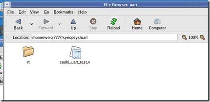
我的文件目录如上所示,测试代码在当前目录下,其余的调用的模块代码在rtl目录下。
所以,要编译。用如下命令:
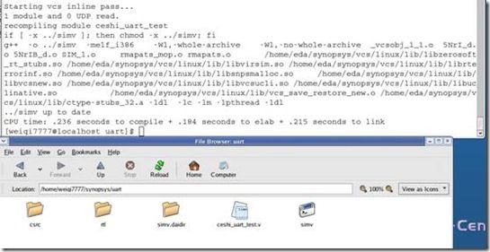
vcs ceshi_uart_test.v -y ./rtl +libext.+v
就进行编译了。-y的作用就是指定搜索路径,因为有可能我们的verilog代码不都是在当前目录下,而是在一个文件夹里面。这样就可以用-y指定该文件夹,这样vcs编译的时候,就会去该目录下去寻找verilog文件。而+libext+.v是指在该搜索路径下,将顶层模块中用到的例化模块都给包括进来。
如果所有的verilog文件都在当前目录下,那么可直接执行
vcs a.v b.v c.v …… (注意,testbench要放在最前面,因为testbench中有`timescale)
如果只是 vcs ceshi_uart_test.v –y ./rtl 就会有如下错误
提示测试文件中的例化模块找不到。
编译完成后,会在当前目录下,生成一个simv文件。 这个文件是一个可执行文件,执行这个文件,就可以看到我们的仿真结果。以文本显示。
命令是 ./simv
因为在testbench中没有写显示内容,所以仿真结果是看不到显示结果的。
可以用dve查看波形。
命令 ./simv –gui
可以看到会有错误,这是因为没有生成vpd文件。VCS的dve是执行vpd文件的。直接vcs verilog文件 是不会产生vpd文件的。要加一个-debug_all或者-debug或者-debug_pp 命令。不过推荐用-debug_all,因为这个可以加断点。
即 vcs ceshi_uart_test.v -y ./rtl +libext.+v -debug_all
然后在 ./simv –gui
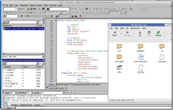
就打开了dve。同时在当前目录下,产生了inter.vpd文件。
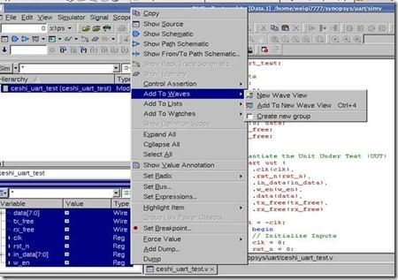
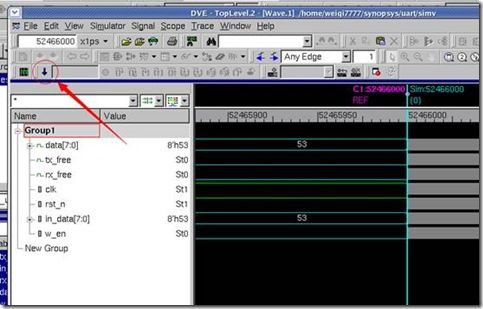
接下来的操作和一般的verilog仿真软件是一样的。选中信号加入到波形中,然后开始仿真。就可以看到波形了。
开始仿真。就可以看到波形了。
接下来是命令行调试。
命令行调试不用看波形,用命令,执行仿真,观看信号。命令行仿真是在ucli中进行的。所以在编译命令中,要加入-ucli。
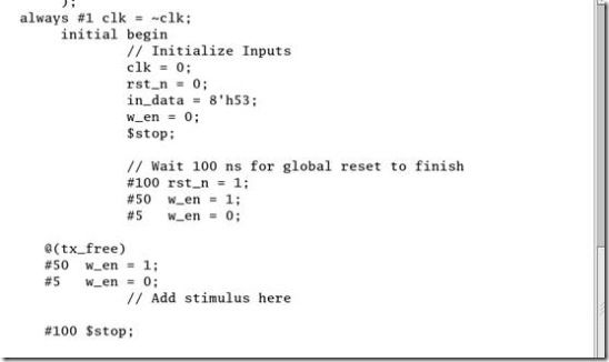
使用命令行调试,可在testbench中加入$stop语句。这样仿真可以在该处停下来,这样可以查看各个信号的值。
如我再testbench中加入两个$stop语句。
执行命令 vcs ceshi_uart_test.v -y ./rtl +libext.+v -debug_all –ucli –R
-R 表示编译后立即执行。
不加这个选项 那执行完上个命令后,在执行命令./simv –ucli 才启动ucli调试。
显示ucli就表示进入ucli调试了。
ucli中有一些常用命令,
scope 显示当前的顶层模块
scope u1 就表示进入到当前顶层模块的u1模块,同时将u1模块设置为顶层模块
scope –up 回到目前顶层模块的上一层。
scope可以用来选择不同的模块,以此来显示不同的信号。因为show是显示当前顶层的信号以及子模块
show 显示当前顶层模块的信号以及子模块
show 信号 –value -radix hex/bin/dec 显示信号的值 以特定的进制显示。
run 运行仿真
run 一直运行,直到遇到$stop或者设置的断点
run time 运行多少时间停止(不推荐)
run -posedge 信号 运行到信号的上升沿停止
run -negedge 信号 运行到信号的下降沿停止
run -change 信号 信号有变化时停止
stop 设置断点
stop 显示断点
stop –posedge 信号 在信号的上升沿设置断点
stop -negedge 信号 在信号的下降沿设置断点
stop -condition {信号表达式} 信号表达式为真的地方设置断点
stop -delete 断点值 删除断点值的断点
restart 重新开启ucli调试模式
-h 帮助命令
命令后面接 –h 显示当前命令的帮助
如 scope –h 显示
接下来就开始调试
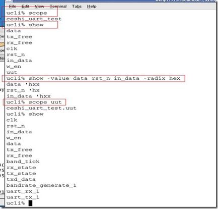
首先scope命令,显示当前顶层为ceshi_uart_test,即我们的testbench模块。
第二个命令 show 显示当前模块下有哪些信号和子模块。可看出,有7个信号,和一个子模块uut。即我们例化的uart_top模块。
第三个命令 show –value 显示信号的值,以16进制显示,因为还没有开始运行,所以信号的值都是x。不定值。
第四个命令 scope uut 进入到uut子模块。当前的顶层模块为uut
第五个命令 show 显示当前顶层模块uut的信号以及子模块,这里有11个信号,3个子模块。
执行scope –up 回到顶层模块。
第六个命令 run命令 在56行有$stop,所以在该处,仿真暂停。
第七个命令 show命令 显示信号的值 因为有些值还没有初始化,所以显示为x。
第八个命令 show命令 显示子模块uut中的信号。调用模块中的信号是用 . 调用的。
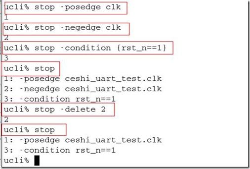
第九个命令 设置断点1 在clk的上升沿设置断点1
第十个命令 设置断点2 在clk的下降沿设置断点2
第十一个命令 设置断点3 在rst为1 设置断点3
第十二个命令 显示断点 设置了三个断点,这里就显示3个断点
第十三个命令 删除断点2 删除在clk下降沿设置的断点2
第十四个命令 显示断点 删除掉了断点2 这里就显示断点1和3
断点设置好后,接下来就run,show 看信号就可以了。
使用restart可以重新开始调试。即仿真时刻回到0时刻。
每次show –value 比较麻烦,可以使用 alias var show –value 用var代替show –value。
如果show –value 信号 就可以 var 信号
以上就是我目前学习到VCS的一些使用心得。当然VCS还有其他的一些命令,由于还没有接触到,这里也没有提到。
copy from http://blog.chinaaet.com/detail/36105
