- Pygame实现记忆拼图游戏3
棉猴
#记忆拼图游戏的编写pygamepython开发语言python游戏编程python游戏代码
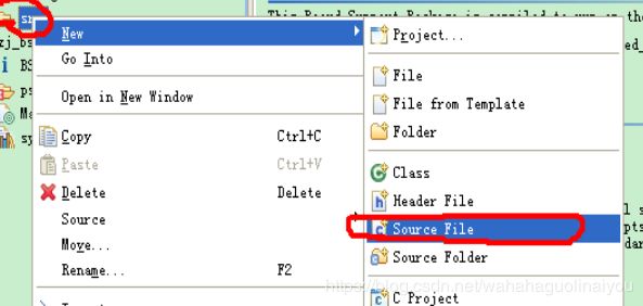
在游戏启动时,需要设置游戏中图案的初始排列,该功能由自定义函数getRandomizedBoard()实现。1按顺序产生游戏所需的不同图案在getRandomizedBoard()中,首先按顺序产生游戏中所需的不同图案。在《Pygame实现记忆拼图游戏2》中提到,游戏中所用的7种颜色保存在ALLCOLORS中,所用的5种形状保存在ALLSHAPES中,通过for循环可以实现7×5=35种组合,代码
- zedboard——adau1761新工程的设备树修改(二)
夜风~
linuxzedboard开发板开发设备树adau1761pl.dtsi
本文将介绍下对工程自动生成的设备树进行修改,加入adau1761设备相关的节点信息。在上一篇文章中,加载hdf文件后,使用petalinux-config指令后,会自动生成设备树文件,共如下图中6个设备树文件。设备树的知识总结见:https://www.cnblogs.com/tureno/articles/6399782.html(1)skeleton.dtsi/**Skeletondevice
- Zedboard 学习记录(一):移植Linaro-ubuntu系统
为中国IC之崛起而读书
FPGA设计VIVADOZedBoard
准备工作:1)启动文件:https://download.csdn.net/download/maochuangan/106892572)ubuntu-linaro系统3)4GB的SD卡4)ZedBoard开发板版本:REV-D5)装有Ubuntu系统的电脑一台(用虚拟机也可以)移植工作:1、将SD卡插到Ubunt电脑中。2、在Linux中进行格式化,并分区。1)在ubuntu系统中搜索disks
- ac3165 linux驱动_[干货]手把手教你用Zedboard学习Linux移植和驱动开发
weixin_39616090
ac3165linux驱动Clover驱动文件夹delphilinuxarmlinuxcan总线接收数据串口打包上传linuxdelphi开发linux配置启动nomad
本文是昨天发的文章《龙芯杯CPU设计竞赛与ZYNQ设计流程介绍》接续部分。重点介绍传统方式的Linux移植和Xilinx的Petalinux的快速移植开发两种。部分硬件设计中需要CPU完成对电路寄存器的配置,为了完成Zedboard对FPGA上部分寄存器的配置功能,可以在PS单元(处理器系统)上运行裸机程序(无操作系统支持)完成和PL单元(FPGA部分)的数据交互功能,此时PS单元更像单片机开发;
- 2022年新版openwifi学习试验之1:编译基于zedboard+fmcomms3的HDL项目生成BIT文件
mcupro
软件无线电OpenOFDM_RXopenwifi学习fpga开发
2022年四月左右,openwifi进行了大的改版,发布了新的版本。这篇BLOG我根据openwifi官方的步骤,实现一下zedboard_fmcomms3平台下的软件编译。本BLOG就是我学习试验https://github.com/open-sdr/openwifi-hw这个页面中讲述的步骤,也是笔记,边做边记录,给大家分享可以让大家少走弯路。步骤1:需要的软件:Pre-conditions:
- Vivado vitis 2023.1 版本 hello world 教学,基于zedboard
春风沂水丶
学习fpga开发单片机嵌入式硬件笔记
vivado部分打开vivado,创建新项目。选择板子,在老版本的vivado中,在Boards里面可以直接搜zedboard,新版本没了。工程建好后新建设计点击加号添加ZYNQ双击ZYNQ进行配置,配置方法可以看我之前的文章:在Vivado中,配置RFSOC的ZYNQ-CSDN博客虽然板子不一样,但是原理是一样的。配置好后点击下图箭头所指的位置,自动连线。最后把时钟连起来就行了。右键刚刚建的设计
- ZedBoard-Linux学习笔记之一
雄关迈步
这几天一直在看有关linux内核和驱动程序设计的书,但总是看一点忘一点,每次都是这样,都快要崩溃了,所以索性把自己每天看的一点内容及时利用博文来记录下来,虽然以后看起来可能会觉得很一般,但是学习是一个需要逐步积累的过程,个人性子比较急,总想着一下就学完这些,但是越看越觉的linux内核是需要花费大量的时间来研究的!开题就先写到这儿吧,开始正文。本文参考自嵌入式linux基础教程第二版【本书已经获得
- 【二 zedboard】PS和PL之间的交互
@晓凡
FPGA学习之路zedboard
PS和PL交互的话采用的是AXI协议,其中又可以分为:AXI-full(完整的AXI协议)、AXI-Stream(流式协议)和AXI-Lite(精简版,一次只能读写一个字,32位的寄存器)。一、原理说明1.在PL端创建IP核,用于向PS发送数据。这一过程通过AXI-Lite协议发送数据到GP接口,GP接口将会把数据放到该IP对应的内存中(已经同一编址)2.在AXI-Lite协议下,与GP接口交互是
- 【OpenHW12参赛手记】ZedBoard-自定义IP核实现+PS成功调用【详细步骤+流程介绍+源码】 转载...
weixin_30639719
嵌入式fpga开发
文章来源图片无法复制,请看原文http://www.eefocus.com/jefby1990/blog/13-03/291975_490bc.html【OpenHW12参赛手记】ZedBoard-自定义IP核实现+PS成功调用【详细步骤+流程介绍+源码】2013-03-0717:56:30分享:(图片请点击查看原图)软件环境:WIN7_64+ISE14.4(system_edition)硬件:Z
- 【ZYNQ 详细案例五】采用AXI4总线封装自定义VGA显示IP核 显示自定义图片或者字符内容 基于ZEDBOARD
Taneeyo
fpga硬件驱动程序
【ZYNQ详细案例五】采用AXI4总线封装自定义VGA显示IP核彩条实验基于ZEDBOARD第一部分:PL部分首先我们先创建工程然后创建blockdesign添加PS处理器自动配置ZEDBOARD的预设。好了以后我们创建一个新IP核因为我们要创建一个AXI4总线标准的IP核,所以这里我们选择AXI4总线的外设NEXTNEXT这一步要选择接口类型、接口模式、以及数据位宽还有寄存器个数。这里因为我们是
- zynq使用lwip远程更新flash
weixin_43189165
zynq
1.目的zynq通过使用以太网实现远程更新flash,同时实现不断电重启,方便用户升级2.硬件环境vivado2018.2使用zynq7开发板zedboard,只需要搭建最小系统包括以太网、uart、flash控制器、ddr3.软件环境搭建硬件环境后,生成bit,导出到sdk该测试环境基于echo模板改动4.软件说明新增qspi_remote_update.h新增qspips.c修改echo.ce
- AD9361+zedboard(ZYNQ7020)的SDK工程(上)
qq_35398084
fpga开发嵌入式硬件
1.准备工具vivado2018.3HDL源码:https://wiki.analog.com/resources/fpga/docs/releasesno_os:https://github.com/analogdevicesinc/no-OS注意:HDL源码下载的版本要与vivado一致,我这里是2018.3HDL版本选择2.构建vivado工程2.1编译源文件解压下载的HDL文件的压缩包进入
- 基于Zynq的GNULinux在线编译调试记录
weixin_30362233
运维开发工具c/c++
--201712281、实验环境硬件环境:联想ThinkPadE430(内存加到10G)、显示屏×2、VGA线×1、HDMI线×1、鼠标×2、键盘×1、USB分线器×1、ZedBoard开发板套件×1、AD-FMCOMMS2-EBZ×1、网线×1、SD卡×1。windows软件环境(E430运行软件):Window7、VMwareWorkstationPro12、串口调试助手、Win32DiskI
- linux fpga 开发环境,- Vivado+Zedboard之Linux开发环境搭建
weixin_39897015
linuxfpga开发环境
自行编译任意版本的方法:下载Qt-lib源码包,此处以qt-everywhere-opensource-src-4.7.3.tar.gz为例注意前面两步是可选的。因为后续我们建立的Qt-ZYNQ库也是这个源码包。添加中文支持:缺少fontconfig造成的,于是重新configure:问题又来了,configure未通过,提示Fontconfig未通过,于是进入/config.tests/x11/
- linux usb 内核签名,ZedBoard上的点灯签名实验(四)配置编译Linux内核和Device Tree...
软实力英语
linuxusb内核签名
做好了内核引导以后,接下来可以编译Linux内核了,编译内核的目的是得到一个内核的镜像,内核镜像是一个可执行文件,把这个镜像放到SD上,以便软核可以直接读取。首先还是先下载Linux内核代码,网址为https://github.com/Digilent/linux-digilent/releases,下载linux-digilent-3.6-digilent-13.01.tar.gz,解压缩#ta
- 【zedboard找不到COM串口bug】驱动下载地址
向盟约宣誓
fpga其他bugfpga开发fpgazedboardzynq
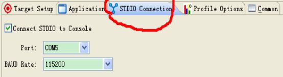
今天在使用zedboard过程中出现了sdk终端没有COM串口的问题:解决方法见【zedboard串口bug最终解决办法】zynq开发在SDK终端Teminal找不到COM3、COM5等接口无法连接uart串口ZYNQ驱动问题解决办法_https://blog.csdn.net/taneeyo/article/details/1149_Taneeyo的博客-CSDN博客以及电脑无法识别zedboa
- zedboard(5)spi轮询和中断
火眼金睛实现统一美
ZYNQ系列fpga开发
一个SPI可以有几个从设备在zynq开发和外部ad相连时,经常需要spi进行寄存器配置,连线一定要注意,MOSI和MISO信号为SDI和SDO。在程序中使用s32XSpiPs_SetSlaveSelect(XSpiPs*InstancePtr,u8SlaveSel)选择。其实就是吧对应设备的ss拉低。备注:只选一个ss,可以不用指定。(感觉,还没测试)这是xspips.c中定义的函数,发送和接收有
- Zynq程序固化到FLASH和SD卡(Zedboard)
火眼金睛实现统一美
ZYNQ系列fpga
本次参考为Zedborad开发板前言:固化的方式不是固定的,每个人习惯的操作不一定,成功之后就会有经验了。这里只是一些个人的实际参考。Flash原理图:根据Flash原理图,管脚配置如下:SD卡原理图:根据SD卡原理图,管脚配置如下:本次要固化的程序作用是打印串口和点亮PL端的8个led灯和MIO7脚的led灯,SDK工程目录如下:详细配置流程:第一步:1.Rightclickonhello_wo
- ZedBoard连接FMCOMMS3在MATLAB中解码ADS-B
zkf0100007
1.打开ADSB_MATLAB,运行ad9361_ModeS(‘192.168.6.10,‘pre-captured’,1)2.AD9361会从MATLAB中读取预先存储的ADSB数据发送出来3.AD9361接收到ADSB信号后会完成解码,MATLAB将解码结果显示出来,如下所示:
- 基于zedboard(zynq7020)使用命令行(sysfs )读取、控制AXI_GPIO开关、led和PS MIO
RyanLee90
ZYNQLINUXlinux
linuxgpio从内核空间导出到用户空间 petalinux在制作Linux系统时,会自动的将gpio从内核空间导出到用户空间,在用户空间下可以通过sysfs方式控制gpio;用户空间位置在/sys/class/gpio,在该文件夹下能看到gpiochipX,X代表gpio的base从那里开始。比如vivado设计用的axi-gpio地址时412000,经过空间导出到用户空间之后,gpioch
- linux 添加spi 驱动,Linux 设备树添加spi设备
nameoverflow
linux添加spi驱动
Linux:4.6应用开发板:zynq系列zc706、zedboard文件系统:ubuntu12参考帖子:https://stackoverflow.com/questions/53634892/linux-spidev-why-it-shouldnt-be-directly-in-devicetree之前实验过spi控制器下面挂载spi设备,当时,关于spi设备树的节点描述如下:spi@e000
- ZYNQ-7 几种DMA的区别与对比
wandering_star
一AXI总线与DMA对于ZYNQ,掌握PS与PL的高速接口;掌握几种DMA的区别与用法;能够编写基于AXI-4总线的用户IP且打包,意味着对ZYNQ器件的掌握已经进入了真正的入门,或中级水平。本篇文章旨在通过简单清晰的描述,让读者快速理解ZYNQ-7000几种DMA的区别。并愿在之后陆续给出几种DMA配合ADC08200、ZedBoard开发板用作数据采集的例子,供参考学习与使用。还望大家支持。二
- ZYNQ:AXI-Stream FIFO驱动程序(PS部分)
坏蛋王师傅
ZYNQfpga开发
最近在用实验室的zedboard学习zynq,在网上找到了一个叫Harald'sEmbeddedElectronics的网站,里面有关于zedboard的一些教学。在做完第六个实验时,打算把PS部分的程序学习和注释并记录下来,于是有了这个帖子。BlockDesign部分中间的AXI-StreamFIFO是我们今天主要控制的对象。最右边的myHeartbeat是这个系列教程的自建IP核,本质上是一个
- 【再话Zedboard】如何在SDK中计算某段程序的执行时间
公孙璃
Zynq学习笔记zedboard
URL:http://blog.chinaaet.com/detail/31789首先赞一下自动保存功能,今天在网页上写的,不小心关掉了,那个心疼啊,幸好有自动保存功能,成功恢复了!废话不多说了,直奔主题吧。计算一段程序的执行时间主要是为了方便计算一些算法的效率,当然,如果能够计算出一段程序的执行时间,也就能够轻松编写出精确延时时间了。调试51单片机的时候,可以可以在Keil中设定断点,直观地计算
- 通过QSPI启动ZedBoard并运行Ramdisk根文件系统
青城悠然
通过SD卡启动Linux,所需时间较长,将系统镜像存储到QSPI中,此过程则会迅捷很多。当然,ZedBoard自带的QSPI只有32MB,文件系统只能选用较小的Ramdisk了,因为此文件系统只存在于DDR中,每次在线对文件系统做了修改,掉电后修改都会消失,相当不便。结论是,此种方式适合简单应用的发布阶段。折腾了几天,从官网获取了各个镜像或者其源码,并生成Mcs后烧录进了QSPI,将系统成功启动。
- 基于vivado(语言Verilog)的FPGA学习(2)——zedboard开机测试和程序烧写
小草莓爸爸
FPGAfpga开发学习
基于vivado(语言Verilog)的FPGA学习(2)——zedboard开机测试和程序烧写终于找到之前写的部分了,在OneNote上,以后还是专注写在一个地方1.系统架构图ZedBoard可以通过四个不同的方法烧写,这些方法是:USB-JTAG这是默认的并且是最直接的烧写ZedBoard的方法,这只要通过ZedBoard工具包的USB到micro-USB连接线就可以直接完成。传统JTAG板卡
- linux4.3.2 块设备驱动简析-1
棒子先生
嵌入式linux—zynq嵌入式zynqlinux驱动块设备
最近比较闲,准备玩玩xilinx的SoC,但又由于预算不够,买不起ZedBoard,所以最后入手了Z-Turn这块板子。它是米尔科技设计的,板子整体是蛮漂亮的,就是软资源不足——不能很好地玩转啊,这是个硬伤。过年在家,闲的无聊,就准备研究一下以前一直想了解的linux中块设备的驱动架构,好吧扯了很多废话,让我们进入正题吧。z-turn这块板子上,系统可以从SPIflash或者TF卡中启动,我们来看
- linux 交叉编译4.8,【参赛手记】Ubuntu Linux 下OpenCV 2.4.3以及Qt 4.8.3的交叉编译
Maggie姐说
linux交叉编译4.8
主机平台(HOST):KUbuntu12.04(HPCQ45308)目标平台(TARGET):嵌入式Linux系统3.x内核(XilinxZEDBoard)由于OpenCV需要进行视频中的运动检测与分割,自然要用到相关函数打开AVI视频.如果只使用OpenCV进行交叉编译,那么默认情况下不支持AVI格式的打开与写入,这是因为少了很多解码库与编码库,如x264,ffmpeg等,因此首先要对这些库进行
- 基于Zedboard和ov5642实现视频采集及VGA输出
Jude_99
ZedBoard音视频
Jude20211024-20211107在网上下载了Pmod-CAM-5M.rar,它是基于Zedboard和ov5640的Demo,我的摄像头是ov5642的,做了一些修改,实现了视频的采集并通过VGA输出。ov5642的代码压缩包ov5642cam_zed.rar稍后会上传。1.ZedBoard和Ov5642的连接把Pmod-CAM-5M.rar解压后,有四个文件夹,根据02和03文件夹的R
- linux qt交叉编译opencv,在zedboard上移植qt+opencv(二):安装交叉编译环境
吴季玄
linuxqt交叉编译opencv
在配置完(一)里面的信息之后,你是不是有种迫不及待的心情向在windows下编写一个程序。和windows不同的是在linux中不需要专门在装一个类似VC之类的应用软件了。在系统中已经有现成的了。一、编写helloworld应用程序Rainysky习惯,也是为了方便,在opt建立了几个文件夹,opt/zedboard/code,并且cd/opt/zedboard/code里面将自己的代码放到里面,
- 数据采集高并发的架构应用
3golden
.net
问题的出发点:
最近公司为了发展需要,要扩大对用户的信息采集,每个用户的采集量估计约2W。如果用户量增加的话,将会大量照成采集量成3W倍的增长,但是又要满足日常业务需要,特别是指令要及时得到响应的频率次数远大于预期。
&n
- 不停止 MySQL 服务增加从库的两种方式
brotherlamp
linuxlinux视频linux资料linux教程linux自学
现在生产环境MySQL数据库是一主一从,由于业务量访问不断增大,故再增加一台从库。前提是不能影响线上业务使用,也就是说不能重启MySQL服务,为了避免出现其他情况,选择在网站访问量低峰期时间段操作。
一般在线增加从库有两种方式,一种是通过mysqldump备份主库,恢复到从库,mysqldump是逻辑备份,数据量大时,备份速度会很慢,锁表的时间也会很长。另一种是通过xtrabacku
- Quartz——SimpleTrigger触发器
eksliang
SimpleTriggerTriggerUtilsquartz
转载请出自出处:http://eksliang.iteye.com/blog/2208166 一.概述
SimpleTrigger触发器,当且仅需触发一次或者以固定时间间隔周期触发执行;
二.SimpleTrigger的构造函数
SimpleTrigger(String name, String group):通过该构造函数指定Trigger所属组和名称;
Simpl
- Informatica应用(1)
18289753290
sqlworkflowlookup组件Informatica
1.如果要在workflow中调用shell脚本有一个command组件,在里面设置shell的路径;调度wf可以右键出现schedule,现在用的是HP的tidal调度wf的执行。
2.designer里面的router类似于SSIS中的broadcast(多播组件);Reset_Workflow_Var:参数重置 (比如说我这个参数初始是1在workflow跑得过程中变成了3我要在结束时还要
- python 获取图片验证码中文字
酷的飞上天空
python
根据现成的开源项目 http://code.google.com/p/pytesser/改写
在window上用easy_install安装不上 看了下源码发现代码很少 于是就想自己改写一下
添加支持网络图片的直接解析
#coding:utf-8
#import sys
#reload(sys)
#sys.s
- AJAX
永夜-极光
Ajax
1.AJAX功能:动态更新页面,减少流量消耗,减轻服务器负担
2.代码结构:
<html>
<head>
<script type="text/javascript">
function loadXMLDoc()
{
.... AJAX script goes here ...
- 创业OR读研
随便小屋
创业
现在研一,有种想创业的想法,不知道该不该去实施。因为对于的我情况这两者是矛盾的,可能就是鱼与熊掌不能兼得。
研一的生活刚刚过去两个月,我们学校主要的是
- 需求做得好与坏直接关系着程序员生活质量
aijuans
IT 生活
这个故事还得从去年换工作的事情说起,由于自己不太喜欢第一家公司的环境我选择了换一份工作。去年九月份我入职现在的这家公司,专门从事金融业内软件的开发。十一月份我们整个项目组前往北京做现场开发,从此苦逼的日子开始了。
系统背景:五月份就有同事前往甲方了解需求一直到6月份,后续几个月也完
- 如何定义和区分高级软件开发工程师
aoyouzi
在软件开发领域,高级开发工程师通常是指那些编写代码超过 3 年的人。这些人可能会被放到领导的位置,但经常会产生非常糟糕的结果。Matt Briggs 是一名高级开发工程师兼 Scrum 管理员。他认为,单纯使用年限来划分开发人员存在问题,两个同样具有 10 年开发经验的开发人员可能大不相同。近日,他发表了一篇博文,根据开发者所能发挥的作用划分软件开发工程师的成长阶段。
初
- Servlet的请求与响应
百合不是茶
servletget提交java处理post提交
Servlet是tomcat中的一个重要组成,也是负责客户端和服务端的中介
1,Http的请求方式(get ,post);
客户端的请求一般都会都是Servlet来接受的,在接收之前怎么来确定是那种方式提交的,以及如何反馈,Servlet中有相应的方法, http的get方式 servlet就是都doGet(
- web.xml配置详解之listener
bijian1013
javaweb.xmllistener
一.定义
<listener>
<listen-class>com.myapp.MyListener</listen-class>
</listener>
二.作用 该元素用来注册一个监听器类。可以收到事件什么时候发生以及用什么作为响
- Web页面性能优化(yahoo技术)
Bill_chen
JavaScriptAjaxWebcssYahoo
1.尽可能的减少HTTP请求数 content
2.使用CDN server
3.添加Expires头(或者 Cache-control) server
4.Gzip 组件 server
5.把CSS样式放在页面的上方。 css
6.将脚本放在底部(包括内联的) javascript
7.避免在CSS中使用Expressions css
8.将javascript和css独立成外部文
- 【MongoDB学习笔记八】MongoDB游标、分页查询、查询结果排序
bit1129
mongodb
游标
游标,简单的说就是一个查询结果的指针。游标作为数据库的一个对象,使用它是包括
声明
打开
循环抓去一定数目的文档直到结果集中的所有文档已经抓取完
关闭游标
游标的基本用法,类似于JDBC的ResultSet(hasNext判断是否抓去完,next移动游标到下一条文档),在获取一个文档集时,可以提供一个类似JDBC的FetchSize
- ORA-12514 TNS 监听程序当前无法识别连接描述符中请求服务 的解决方法
白糖_
ORA-12514
今天通过Oracle SQL*Plus连接远端服务器的时候提示“监听程序当前无法识别连接描述符中请求服务”,遂在网上找到了解决方案:
①打开Oracle服务器安装目录\NETWORK\ADMIN\listener.ora文件,你会看到如下信息:
# listener.ora Network Configuration File: D:\database\Oracle\net
- Eclipse 问题 A resource exists with a different case
bozch
eclipse
在使用Eclipse进行开发的时候,出现了如下的问题:
Description Resource Path Location TypeThe project was not built due to "A resource exists with a different case: '/SeenTaoImp_zhV2/bin/seentao'.&
- 编程之美-小飞的电梯调度算法
bylijinnan
编程之美
public class AptElevator {
/**
* 编程之美 小飞 电梯调度算法
* 在繁忙的时间,每次电梯从一层往上走时,我们只允许电梯停在其中的某一层。
* 所有乘客都从一楼上电梯,到达某层楼后,电梯听下来,所有乘客再从这里爬楼梯到自己的目的层。
* 在一楼时,每个乘客选择自己的目的层,电梯则自动计算出应停的楼层。
* 问:电梯停在哪
- SQL注入相关概念
chenbowen00
sqlWeb安全
SQL Injection:就是通过把SQL命令插入到Web表单递交或输入域名或页面请求的查询字符串,最终达到欺骗服务器执行恶意的SQL命令。
具体来说,它是利用现有应用程序,将(恶意)的SQL命令注入到后台数据库引擎执行的能力,它可以通过在Web表单中输入(恶意)SQL语句得到一个存在安全漏洞的网站上的数据库,而不是按照设计者意图去执行SQL语句。
首先让我们了解什么时候可能发生SQ
- [光与电]光子信号战防御原理
comsci
原理
无论是在战场上,还是在后方,敌人都有可能用光子信号对人体进行控制和攻击,那么采取什么样的防御方法,最简单,最有效呢?
我们这里有几个山寨的办法,可能有些作用,大家如果有兴趣可以去实验一下
根据光
- oracle 11g新特性:Pending Statistics
daizj
oracledbms_stats
oracle 11g新特性:Pending Statistics 转
从11g开始,表与索引的统计信息收集完毕后,可以选择收集的统信息立即发布,也可以选择使新收集的统计信息处于pending状态,待确定处于pending状态的统计信息是安全的,再使处于pending状态的统计信息发布,这样就会避免一些因为收集统计信息立即发布而导致SQL执行计划走错的灾难。
在 11g 之前的版本中,D
- 快速理解RequireJs
dengkane
jqueryrequirejs
RequireJs已经流行很久了,我们在项目中也打算使用它。它提供了以下功能:
声明不同js文件之间的依赖
可以按需、并行、延时载入js库
可以让我们的代码以模块化的方式组织
初看起来并不复杂。 在html中引入requirejs
在HTML中,添加这样的 <script> 标签:
<script src="/path/to
- C语言学习四流程控制if条件选择、for循环和强制类型转换
dcj3sjt126com
c
# include <stdio.h>
int main(void)
{
int i, j;
scanf("%d %d", &i, &j);
if (i > j)
printf("i大于j\n");
else
printf("i小于j\n");
retu
- dictionary的使用要注意
dcj3sjt126com
IO
NSDictionary *dict = [NSDictionary dictionaryWithObjectsAndKeys:
user.user_id , @"id",
user.username , @"username",
- Android 中的资源访问(Resource)
finally_m
xmlandroidStringdrawablecolor
简单的说,Android中的资源是指非代码部分。例如,在我们的Android程序中要使用一些图片来设置界面,要使用一些音频文件来设置铃声,要使用一些动画来显示特效,要使用一些字符串来显示提示信息。那么,这些图片、音频、动画和字符串等叫做Android中的资源文件。
在Eclipse创建的工程中,我们可以看到res和assets两个文件夹,是用来保存资源文件的,在assets中保存的一般是原生
- Spring使用Cache、整合Ehcache
234390216
springcacheehcache@Cacheable
Spring使用Cache
从3.1开始,Spring引入了对Cache的支持。其使用方法和原理都类似于Spring对事务管理的支持。Spring Cache是作用在方法上的,其核心思想是这样的:当我们在调用一个缓存方法时会把该方法参数和返回结果作为一个键值对存放在缓存中,等到下次利用同样的
- 当druid遇上oracle blob(clob)
jackyrong
oracle
http://blog.csdn.net/renfufei/article/details/44887371
众所周知,Oracle有很多坑, 所以才有了去IOE。
在使用Druid做数据库连接池后,其实偶尔也会碰到小坑,这就是使用开源项目所必须去填平的。【如果使用不开源的产品,那就不是坑,而是陷阱了,你都不知道怎么去填坑】
用Druid连接池,通过JDBC往Oracle数据库的
- easyui datagrid pagination获得分页页码、总页数等信息
ldzyz007
var grid = $('#datagrid');
var options = grid.datagrid('getPager').data("pagination").options;
var curr = options.pageNumber;
var total = options.total;
var max =
- 浅析awk里的数组
nigelzeng
二维数组array数组awk
awk绝对是文本处理中的神器,它本身也是一门编程语言,还有许多功能本人没有使用到。这篇文章就单单针对awk里的数组来进行讨论,如何利用数组来帮助完成文本分析。
有这么一组数据:
abcd,91#31#2012-12-31 11:24:00
case_a,136#19#2012-12-31 11:24:00
case_a,136#23#2012-12-31 1
- 搭建 CentOS 6 服务器(6) - TigerVNC
rensanning
centos
安装GNOME桌面环境
# yum groupinstall "X Window System" "Desktop"
安装TigerVNC
# yum -y install tigervnc-server tigervnc
启动VNC服务
# /etc/init.d/vncserver restart
# vncser
- Spring 数据库连接整理
tomcat_oracle
springbeanjdbc
1、数据库连接jdbc.properties配置详解 jdbc.url=jdbc:hsqldb:hsql://localhost/xdb jdbc.username=sa jdbc.password= jdbc.driver=不同的数据库厂商驱动,此处不一一列举 接下来,详细配置代码如下:
Spring连接池
- Dom4J解析使用xpath java.lang.NoClassDefFoundError: org/jaxen/JaxenException异常
xp9802
用Dom4J解析xml,以前没注意,今天使用dom4j包解析xml时在xpath使用处报错
异常栈:java.lang.NoClassDefFoundError: org/jaxen/JaxenException异常
导入包 jaxen-1.1-beta-6.jar 解决;
&nb