Win32 Series - DIB Displaying and Printing
http://www-user.tu-chemnitz.de/~heha/petzold/
Displaying and Printing
Bitmaps are for looking at. In this section, we'll begin by looking at the two functions that Windows supports for displaying a DIB on the video display or a printer page. For better performance, you may eventually prefer a more roundabout method for displaying bitmaps that I'll discuss later in this chapter. But these two functions are a logical first start.
The two functions are called SetDIBitsToDevice (pronounced "set dee eye bits to device") andStretchDIBits ("stretch dee eye bits"). Each function uses a DIB stored in memory and can display the entire DIB or a rectangular portion of it. When you useSetDIBitsToDevice, the size of the displayed image in pixels will be the same as the pixel size of the DIB. For example, a 640-by-480 DIB will cover your entire standard VGA screen, but on your 300-dpi laser printer it will be only about 2.1 by 1.6 inches. The StretchDIBits function can stretch or shrink the row and column dimension of a DIB to display it in a particular size on the output device.
Digging into the DIB
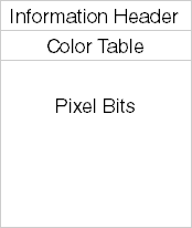
When you call one of the two functions to display a DIB, you need several pieces of information about the image. As I discussed earlier, DIB files contain the following sections:
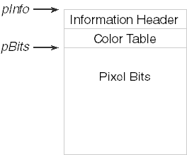
A DIB file can be loaded into memory. If the entire file less the file header is stored in a contiguous block of memory, a pointer to the beginning of the block (which is the beginning of the information header) is said to address a packed DIB. (See below.)
This is the format you use when transferring a DIB through the clipboard, and it's also the format you use when creating a brush from a DIB. The packed DIB is a convenient way to store a DIB in memory because the entire DIB is referenced by a single pointer (for example, pPackedDib), which you can define as a pointer to a BYTE. Using the structure definitions shown earlier in this chapter, you can get at all the information stored in the DIB, including the color table and the individual pixel bits.
However, getting at much of this information requires several lines of code. For example, you can't simply access the pixel width of the DIB using the statement
iWidth = ((PBITMAPINFOHEADER) pPackedDib)->biWidth ;
It's possible that the DIB is in the OS/2-compatible format. In that format, the packed DIB begins with a BITMAPCOREHEADER structure and the pixel width and height of the DIB are stored as 16-bit WORDs rather than 32-bit LONGs. So, you first have to check if the DIB is in the old format and then proceed accordingly:
if (((PBITMAPCOREHEADER) pPackedDib)->bcSize == sizeof (BITMAPCOREHEADER))
     iWidth = ((PBITMAPCOREHEADER) pPackedDib)->bcWidth ;
else
     iWidth = ((PBITMAPINFOHEADER) pPackedDib)->biWidth ;
This isn't all that bad, of course, but it's certainly not as clean as we'd prefer.
Now here's a fun exercise: given a pointer to a packed DIB, find the value of the pixel at coordinate (5, 27). Even if you assume that the DIB is not in the OS/2-compatible format, you need to know the width, height, and bit count of the DIB. You need to calculate the byte length of each row of pixels. You need to determine the number of entries in the color table, and whether the color table includes three 32-bit color masks. And you need to check whether the DIB is compressed, in which case the pixel is not directly addressable.
If you need to directly access all the pixels of the DIB (as you do when performing many image-processing jobs), this can add up to quite a bit of processing time. For this reason, while maintaining a pointer to a packed DIB may be convenient, it certainly doesn't lend itself to efficient code. An excellent solution is defining a C++ class for DIBs that includes enough member data to allow the very speedy random access of DIB pixels. However, since I promised at the outset of this book that you need not know any C++, I'll show you a C solution instead in the next chapter.
For the SetDIBitsToDevice and StretchDIBits functions, the information you need includes a pointer to the BITMAPINFO structure of the DIB. As you'll recall, the BITMAPINFO structure comprises the BITMAPINFOHEADER structure and the color table. So, this is simply a pointer to the packed DIB with appropriate casting.
The functions also require a pointer to the pixel bits. This is derivable from information in the information header, although the code is not pretty. Notice that this pointer can be calculated much more easily when you have access to the bfOffBits field of the BITMAPFILEHEADER structure. The bfOffBits field indicates the offset from the beginning of the DIB file to the pixel bits. You could simply add this offset to the BITMAPINFO pointer and then subtract the size of the BITMAPFILEHEADER structure. However, this doesn't help when you get a pointer to a packed DIB from the clipboard, because you don't have a BITMAPFILEHEADER structure. This diagram shows the two pointers you need:
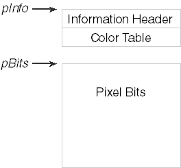
The SetDIBitsToDevice and StretchDIBits functions require two pointers to the DIB because the two sections do not have to be in one contiguous block of memory. You could have two blocks of memory like so:
Indeed, breaking a DIB into two memory blocks like this is quite useful. It's only because we're preferring for the moment to work with packed DIBs that the entire DIB is stored in a single memory block.
Besides these two pointers, the SetDIBitsToDevice and StretchDIBits functions also usually require the pixel width and height of the DIB. If you're displaying only part of the DIB, then you don't need these values explicitly, but they'll define an upper limit for a rectangle you define within the array of DIB pixel bits.
Pixel to Pixel
The SetDIBitsToDevice function displays a DIB without any stretching or shrinking. Each pixel of the DIB is mapped to a pixel of the output device. The image is always displayed correctly oriented—that is, with the top row of the image on top. Any transforms that might be in effect for the device context determine the starting position where the DIB is displayed but otherwise have no effect on the size or orientation of the image. Here's the function:
iLines = SetDIBitsToDevice (
               hdc,           // device context handle
               xDst,          // x destination coordinate
               yDst,          // y destination coordinate
               cxSrc,         // source rectangle width
               cySrc,         // source rectangle height
               xSrc,          // x source coordinate
               ySrc,          // y source coordinate
               yScan,         // first scan line to draw
               cyScans,       // number of scan lines to draw
               pBits,         // pointer to DIB pixel bits
               pInfo,         // pointer to DIB information
               fClrUse) ;     // color use flag
Don't be too put off by the number of arguments. For most purposes, the function is easier to use than it initially appears. For other purposes, well…it's a mess. But we'll work it out.
As usual for GDI display functions, the first argument to SetDIBitsToDevice is the handle of the device context indicating the device on which you want to display the DIB. The next two arguments,xDst and yDst, are logical coordinates of the output device and indicate the coordinate where the top left corner of the DIB image is to appear. (By "top" I mean the visual top of the image, not the first row of pixels in the DIB.) Note that these are logical coordinates, so they are subject to any mapping mode that may be in effect or—in the case of Windows NT—any transform you may have set. In the default MM_TEXT mapping mode, you would set both these arguments equal to 0 to display the DIB image flush against the left side and top of the display surface.
You can display the entire DIB image or only part of it. That's the purpose of the next four arguments. But here's where the upside-down orientation of DIB pixel data creates some real perversion that I'll discuss shortly. For now, be aware that to display the entire DIB, you set xSrc and ySrc equal to 0 and cxSrc andcySrc equal to the pixel width and height of the DIB, respectively. Note that because the biHeight field of the BITMAPINFOHEADER structure will be negative for top-down DIBs, cySrc should be set to the absolute value of the biHeight field.
The documentation of this function (/Platform SDK/Graphics and Multimedia Services/GDI/Bitmaps/Bitmap Reference/Bitmap Functions/SetDIBitsToDevice) says that the xSrc, ySrc, cxSrc, and cySrc arguments are in logical units. This is not true. They are pixel coordinates and dimensions. It makes no sense for the pixels within a DIB to have logical coordinates and units. Moreover, regardless of the mapping mode, a DIB displayed on an output device will always be cxSrc pixels wide and cySrc pixels high.
Let me also skip a detailed discussion of the next two arguments, yScan andcyScan, for now. These arguments let you reduce memory requirements by displaying a DIB sequentially a bit at a time as you read it from a disk file or a modem connection. Usually, you setyScan to 0 and cyScan to the height of the DIB.
The pBits argument is a pointer to the DIB pixel bits. The pInfo argument is a pointer to the BITMAPINFO structure of the DIB. Although the address of the BITMAPINFO structure is the same as the address of the BITMAPINFOHEADER structure, the SetDIBitsToDevice function is defined to use the BITMAPINFO structure as a subtle hint: for 1-bit, 4-bit, and 8-bit DIBs, the bitmap information header must be followed by a color table. Although defined as a pointer to a BITMAPINFO structure, this argument can also be a pointer to a BITMAPCOREINFO, BITMAPV4HEADER, or BITMAPV5HEADER structure.
The last argument is either DIB_RGB_COLORS or DIB_PAL_COLORS, defined in WINGDI.H as 0 and 1, respectively. For now you'll use DIB_RGB_COLORS, which means that the DIB contains a color table. The DIB_PAL_COLORS flag indicates that the color table in the DIB has been replaced with 16-bit indices into a logical color palette selected and realized in a device context. We'll learn about this option in the next chapter. For now, use DIB_RGB_COLORS, or simply 0 if you're lazy.
The SetDIBitsToDevice function returns the number of scan lines it displays.
So, to call SetDIBitsToDevice to display an entire DIB image, you'll need the following information:
hdc The device context handle to the destination surface. xDst and yDst The destination coordinates of the top left corner of the image. cxDib and cyDib The pixel width and height of the DIB, where cyDib is the absolute value of the biHeight field in the BITMAPINFOHEADER structure. pInfo and pBits Pointers to the bitmap information section and the pixel bits.You then call SetDIBitsToDevice like so:
SetDIBitsToDevice (
     hdc,      // device context handle
     xDst,     // x destination coordinate
     yDst,     // y destination coordinate
     cxDib,    // source rectangle width
     cyDib,    // source rectangle height
     0,        // x source coordinate
     0,        // y source coordinate
     0,        // first scan line to draw
     cyDib,    // number of scan lines to draw
     pBits,    // pointer to DIB pixel bits
     pInfo,    // pointer to DIB information
     0) ;      // color use flag
So, out of the 12 arguments to the DIB, four are commonly set to 0 and another is repeated. The SHOWDIB1 program in Figure 15-2 displays a DIB by using the SetDIBitsToDevice function.
Figure 15-2. The SHOWDIB1 program.
SHOWDIB1.C/*----------------------------------------------
SHOWDIB1.C -- Shows a DIB in the client area
(c) Charles Petzold, 1998
----------------------------------------------*/
#include |
DIBFILE.H/*---------------------------------------- DIBFILE.H -- Header File for DIBFILE.C ----------------------------------------*/ void DibFileInitialize (HWND hwnd) ; BOOL DibFileOpenDlg (HWND hwnd, PTSTR pstrFileName, PTSTR pstrTitleName) ; BOOL DibFileSaveDlg (HWND hwnd, PTSTR pstrFileName, PTSTR pstrTitleName) ; BITMAPFILEHEADER * DibLoadImage (PTSTR pstrFileName) ; BOOL DibSaveImage (PTSTR pstrFileName, BITMAPFILEHEADER *) ; |
DIBFILE.C/*--------------------------------- DIBFILE.C -- DIB File Functions ---------------------------------*/ #include |
SHOWDIB1.RC (excerpts)//Microsoft Developer Studio generated resource script.
#include "resource.h"
#include "afxres.h"
/////////////////////////////////////////////////////////////////////////////
// Menu
SHOWDIB1 MENU DISCARDABLE
BEGIN
POPUP "&File"
BEGIN
MENUITEM "&Open...", IDM_FILE_OPEN
MENUITEM "&Save...", IDM_FILE_SAVE
END
END
|
RESOURCE.H (excerpts)// Microsoft Developer Studio generated include file. // Used by ShowDib1.rc #define IDM_FILE_OPEN 40001 #define IDM_FILE_SAVE 40002 |
The DIBFILE.C file contains routines to display the File Open and File Save dialog boxes and also to load an entire DIB file (complete with the BITMAPFILEHEADER structure) into a single block of memory. The program can also write out such a memory block to a file.
After loading in a DIB file while processing the File Open command in SHOWDIB1.C, the program calculates the offsets of the BITMAPINFOHEADER structure and the pixel bits within the memory block. The program also obtains the pixel width and height of the DIB. All of this information is stored in static variables. During the WM_PAINT message, the program displays the DIB by calling SetDIBitsToDevice.
Of course, SHOWDIB1 is missing a few features. For instance, if the DIB is too big for the client area, there are no scroll bars to move it into view. These are deficiencies that will be fixed before the end of the next chapter.
The Topsy-Turvy World of DIBs
We are about to learn an important lesson, not only in life but in the design of application program interfaces for operating systems. That lesson is: if you screw something up at the beginning, it only gets more screwed up when you later try to patch it.
Back when the bottom-up definition of the DIB pixel bits originated in the OS/2 Presentation Manager, it made some degree of sense because everything in PM has a default bottom left origin. For example, within a PM window, the default (0,0) origin is the lower left corner of the window. (If this sounds wacky to you, you're not alone. If it doesn't sound wacky, you're probably a mathematician.) The bitmap-drawing functions also specified a destination in terms of lower left coordinates.
So, in OS/2, if you specified a destination coordinate of (0,0) for the bitmap, the image would appear flush against the left and bottom of the window, as in Figure 15-3.
Figure 15-3. A bitmap as it would be displayed under OS/2 with a (0,0) destination.
With a slow enough machine, you could actually see the bitmap being drawn from the bottom to the top.
While the OS/2 coordinate system may seem wacky, it has the virtue of being highly consistent. The (0,0) origin of the bitmap is the first pixel of the first row in the bitmap file, and this pixel is mapped to the destination coordinate indicated in the bitmap-drawing functions.
The problem with Windows is that internal consistency was not maintained. When you want to display only a rectangular subset within the entire DIB image, you use the argumentsxSrc, ySrc, cxSrc, and cySrc. These source coordinates and sizes are relative to the first row of the DIB data, which is the bottom row of the image. That's just like OS/2. However, unlike OS/2, Windows displays the top row of the image at the destination coordinate. Thus, if you're displaying the entire DIB image, the pixel displayed at (xDst,yDst) is the DIB pixel at coordinate (0, cyDib - 1). That's the last row of DIB data but the top row of the image. If you're displaying only part of the image, the pixel displayed at (xDst,yDst) is the DIB pixel at coordinate (xSrc, ySrc + cySrc - 1).
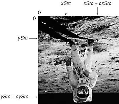
Figure 15-4 shows a diagram to help you figure this out. The DIB below is shown as you might imagine it stored in memory—that is, upside-down. The origin from which the coordinates are measured is coincident with the first bit of pixel data in the DIB. The xSrc argument to SetDIBitsToDevice is measured from the left of the DIB, and cxSrc is the width of the image to the right of xSrc. That's straightforward. The ySrc argument is measured from the first row of the DIB data (that is, the bottom of the image), and cySrc is the height of image from ySrc towards the last row of the data (the top of the image).
Figure 15-4. Specifying DIB coordinates for normal (bottom-up) DIBs.
If the destination device context has default pixel coordinates using the MM_TEXT mapping mode, the relationship between the corner coordinates of the source and destination rectangles will be those shown in the table below:
| Source Rectangle | Destination Rectangle |
| (xSrc, ySrc) | (xDst, yDst + cySrc - 1)) |
| (xSrc + cxSrc - 1,ySrc) | (xDst + cxSrc - 1,yDst + cySrc - 1) |
| (xSrc,ySrc + cySrc - 1) | (xDst, yDst) |
| (xSrc + cxSrc - 1,ySrc + cySrc - 1) | (xDst + cxSrc - 1, yDst) |
That (xSrc, ySrc) does not map to (xDst, yDst) is what makes this so chaotic. With any other mapping mode, the point (xSrc,ySrc + cySrc - 1) will still map to the logical point (xDst,yDst) and the image will look the same as it does in MM_TEXT.
So far, I've been discussing the normal case when the biHeight field of the BITMAPINFOHEADER structure is positive. If the biHeight field is negative, the DIB data is arranged in a rational top-down manner. You may believe that this clears up all the problems. If so, you would be very naive.
Apparently someone decided that if you take a top-down DIB, flip all the rows around, and then set thebiHeight field to a positive value, it should work the same as a normal bottom-up DIB. Any existing code that referenced a rectangle of the DIB shouldn't have to be modified. That's a reasonable objective, I suppose, but it doesn't take into account the fact that programs need to be modified anyway to deal with top-down DIBs so as not to use a negative height.
Moreover, the result of this decision has strange implications. It means that source coordinates of top-down DIBs have an origin at the last row of the DIB data, which is also the bottom row of the image. This is completely alien to anything we've yet encountered. The DIB pixel at the (0,0) origin is no longer the first pixel referenced by the pBits pointer. Nor is it the last pixel in the DIB file. It's somewhere in between.
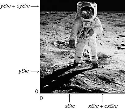
Figure 15-5 shows a diagram indicating how you specify a rectangle within a top-down DIB, again showing the DIB as it is stored in the file or in memory:
Figure 15-5. Specifying DIB coordinates for top-down DIBs.
At any rate, the real advantage of this scheme is that the arguments to the SetDIBitsToDevice function are independent of the orientation of the DIB data. If you have two DIBs (one bottom-up and the other top-down) that show the same image (which means that the order of rows in the two DIB files are opposite each other), you can select the same part of the image to display using identical arguments to SetDIBitsToDevice.
This is demonstrated in the APOLLO11 program shown in Figure 15-6.
Figure 15-6. The APOLLO11 program.
APOLLO11.C/*----------------------------------------------
APOLLO11.C -- Program for screen captures
(c) Charles Petzold, 1998
----------------------------------------------*/
#include |
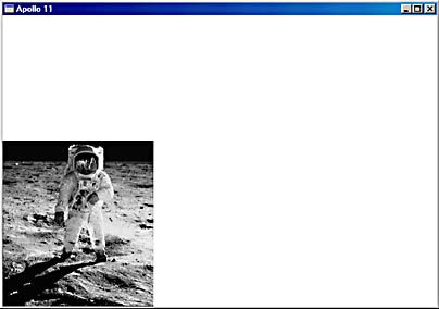
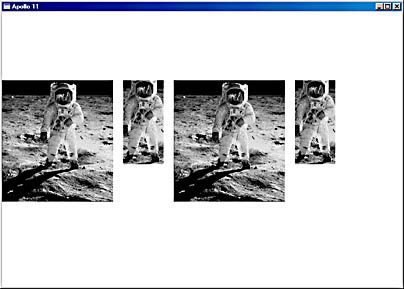
The program loads two DIBS, named APOLLO11.BMP (the bottom-up version) and APOLLOTD.BMP (the top-down version). Both are 220 pixels wide and 240 pixels high. Note that when the program determines the DIB width and height from the header information structure, it uses the abs function to take the absolute value of the biHeight field. When displaying the DIBs in full size or in the partial views, the xSrc, ySrc, cxSrc, and cySrc coordinates are identical regardless of which bitmap is being displayed. The results are shown in Figure 15-7.
Figure 15-7. The APOLLO11 display.
Notice that the "first scan line" and "number of scan lines" arguments remain unchanged. I'll get to those shortly. The pBits argument is also unchanged. Don't try to alter pBits so that it points only to the area of the DIB you wish to display.
I'm spending so much time on this issue not because I have a desire to knock the Windows developers for attempting their best to reconcile problematic areas in the definition of the API, but because you shouldn't be nervous if this seems to be confusing. It's confusing because it's confused.
I also want you to be alert to certain statements in the Windows documentation such as this one forSetDIBitsToDevice: "The origin of a bottom-up DIB is the lower left corner of the bitmap; the origin of a top-down DIB is the upper left corner." That's not only ambiguous, it's just plain wrong. We can better state the difference like so: The origin of a bottom-up DIB is the bottom left corner of the bitmap image, which is the first pixel of the first row of bitmap data. The origin of a top-down DIB is also the bottom left corner of the bitmap image, but in this case the bottom left corner is the first pixel of the last row of bitmap data.
The problem gets worse if you need to write a function that lets your programs access individual bits of a DIB. This should be consistent with the way that you specify coordinates for displaying partial DIB images. My solution (which I'll implement in a DIB library in Chapter 16) is to uniformly reference DIB pixels and coordinates as if the (0,0) origin refers to the leftmost pixel of the top row of the DIB image as seen when correctly displayed.
Sequential Display
Having lots of memory sure makes programming easier. Displaying a DIB that's located in a disk file can be broken into two completely independent jobs: loading the DIB into memory and then displaying it.
Regardless, there might be times when you would like to display a DIB without requiring that the entire file be loaded into memory. Even if enough physical memory is available for the DIB, moving the DIB into memory can force Windows' virtual memory system to move other code and data out to disk. This can be particularly distressing if the DIB is needed only for display and can then be immediately discarded from memory.
Here's another problem: Suppose the DIB resides on a slow storage medium such as a floppy disk. Or it's coming over a modem. Or it's coming from a conversion routine that's getting pixel data from a scanner or a video frame grabber. Do you want to wait until the entire DIB is loaded into memory before you display it? Or would you rather display the DIB sequentially right as it's coming off the disk or through the telephone line or from the scanner?
Solving these problems is the purpose of the yScan and cyScans arguments to the SetDIBitsToDevice function. To use this feature, you make multiple calls to SetDIBitsToDevice, mostly with the same arguments. However, for each call, the pBits argument points to different sections of the total array of bitmap pixels. The yScans argument indicates which row of pixel data pBits is pointing to, and the cyScans argument is the number of rows referenced by pBits. This reduces memory requirements considerably. You need allocate only enough memory to hold the information section of the DIB (the BITMAPINFOHEADER structure and the color table) and at least 1 row of pixel data.
For example, suppose the DIB has 23 rows of pixels. You wish to display this DIB in blocks of 5 rows. You'll probably want to allocate a block of memory, referenced by the variablepInfo, to store the BITMAPINFO section of the DIB. Then read it in from the file. After examining the fields of this structure, you can calculate the byte length of a row. Multiply by 5 and allocate another block (pBits) of that size. Now read in the first 5 rows. Call the function as you would normally, but with yScan set equal to 0 and cyScans set equal to 5. Now read the next 5 rows from the file. This time set yScan equal to 5. Continue with yScan set to 10 and then 15. Finally, read the last 3 rows into the block addressed bypBits, and call SetDIBitsToDevice with yScan set to 20 and cyScans set to 3.
Now here's the bad news. First, using this feature of SetDIBitsToDevice requires a fairly close coupling between the data acquisition and the data presentation elements of your program. This is usually undesirable because you have to alternate between getting the data and showing it. Overall, you'll slow down the entire process. Secondly, SetDIBitsToDevice is the only bitmap-display function that has this feature. As we'll see, the StretchDIBits function does not include this feature, so you can't use it to display the incoming DIB in a different pixel size. You'd have to fake it by calling StretchDIBits multiple times, each time altering information in the BITMAPINFOHEADER structure and displaying the results in a different area of the screen.
The SEQDISP program in Figure 15-8 demonstrates how to use this feature.
Figure 15-8. The SEQDISP program.
SEQDISP.C/*-----------------------------------------
SEQDISP.C -- Sequential Display of DIBs
(c) Charles Petzold, 1998
-----------------------------------------*/
#include |
SEQDISP.RC (excerpts)//Microsoft Developer Studio generated resource script.
#include "resource.h"
#include "afxres.h"
/////////////////////////////////////////////////////////////////////////////
// Accelerator
SEQDISP ACCELERATORS DISCARDABLE
BEGIN
"O", IDM_FILE_OPEN, VIRTKEY, CONTROL, NOINVERT
END
/////////////////////////////////////////////////////////////////////////////
// Menu
SEQDISP MENU DISCARDABLE
BEGIN
POPUP "&File"
BEGIN
MENUITEM "&Open...\tCtrl+O", IDM_FILE_OPEN
END
END
|
RESOURCE.H (excerpts)// Microsoft Developer Studio generated include file. // Used by SeqDisp.rc #define IDM_FILE_OPEN 40001 |
All the file I/O in SEQDISP.C occurs while processing the File Open menu command. Toward the end of WM_COMMAND processing, the program enters a loop that reads single lines of pixels and displays them with SetDIBitsToDevice. The entire DIB is retained in memory so that it can be displayed also during WM_PAINT processing.
Stretching to Fit
SetDIBitsToDevice does a pixel-to-pixel display of a DIB to an output device. This is probably not good for printing DIBs. The better the resolution of the printer, the tinier the image you'll get. You could end up with something the size of a postage stamp.
To display a DIB in a particular size on the output device by shrinking or stretching it, you can useStretchDIBits:
iLines = StretchDIBits (
               hdc,           // device context handle
               xDst,          // x destination coordinate
               yDst,          // y destination coordinate
               cxDst,         // destination rectangle width
               cyDst,         // destination rectangle height
               xSrc,          // x source coordinate
               ySrc,          // y source coordinate
               cxSrc,         // source rectangle width
               cySrc,         // source rectangle height
               pBits,         // pointer to DIB pixel bits
               pInfo,         // pointer to DIB information
               fClrUse,       // color use flag
               dwRop) ;       // raster operation
The function arguments are the same as SetDIBitsToDevice with three exceptions:
The destination coordinates include a logical width ( cxDst) and height ( cyDst) as well as starting points. There is no facility to reduce memory requirements by displaying the DIB sequentially. The last argument is a raster operation, which indicates how the pixels of the DIB are combined with the pixels of the output device. We learned about these in the last chapter. For now, we'll be using SRCCOPY for this argument.There's actually another difference that is more subtle. If you look at the declaration ofSetDIBitsToDevice, you'll find that cxSrc and cySrc are DWORDs, which are 32-bit unsigned long integers. InStretchDIBits, cxSrc and cySrc (as well as cxDst andcyDst) are defined as signed integers, which implies that they can be negative. Indeed they can, as we'll shortly see. But let me add a bit of clarification if you've started examining whether other arguments can be negative: In both functions, xSrc and ySrc are defined as int values, but that's an error. These values are always nonnegative.
A source rectangle within the DIB is mapped to a destination rectangle as shown in the following table.
| Source Rectangle | Destination Rectangle |
| (xSrc, ySrc) | (xDst, yDst + cyDst - 1) |
| (xSrc + cxSrc - 1, ySrc) | (xDst + cxDst - 1, yDst + cyDst - 1) |
| (xSrc, ySrc + cySrc - 1) | (xDst, yDst) |
| (xSrc + cxSrc - 1, ySrc + cySrc - 1) | (xDst + cxDst - 1, yDst) |
The -1 terms in the right column are not quite accurate because the degree of stretch (as well as the mapping mode and other transforms) can cause the results to be slightly different.
As an example, let's think about a 2×2 DIB, where the xSrc and ySrc arguments to StretchDIBits are both 0 and cxSrc and cySrc are both 2. Assume we're displaying to a device context with the MM_TEXT mapping mode and no transforms. If xDst and yDst are both 0 and cxDst and cyDst are both 4, then we're stretching the DIB by a factor of 2. Each source pixel (x,y) will map to four destination pixels as shown here:
(0,0) --> (0,2) and (1,2) and (0,3) and (1,3)
(1,0) --> (2,2) and (3,2) and (2,3) and (3,3)
(0,1) --> (0,0) and (1,0) and (0,1) and (1,1)
(1,1) --> (2,0) and (3,0) and (2,1) and (3,1)
The table shown above correctly indicates the corners of the destination, which are (0, 3), (3, 3), (0, 0), and (3, 0). In other cases, the coordinates might be only approximate.
SetDIBitsToDevice is affected by the mapping mode of the destination device context only to the extent thatxDst and yDst are logical coordinates. StretchDIBits is fully affected by the mapping mode. For example, if you've set one of the metric mapping modes where values ofy increase going up the display, the DIB will be displayed upside-down.
You can compensate for this by making cyDst negative. Indeed, you can make any of the width and height parameters negative to flip the DIB horizontally or vertically. In the MM_TEXT mapping mode, ifcySrc and cyDst are opposite signs, the DIB will be flipped around the horizontal axis and will appear to be upside-down. If cxSrc and cxDst are opposite signs, the DIB is flipped on its vertical axis and will appear to be a mirror image.
Here are a couple of expressions that summarize this. In these expressions, xMM and yMM indicate the orientation of the mapping mode; xMM is 1 if values ofx increase moving to the right and -1 if values of x increase moving to the left. Similarly, yMM is 1 if values of y increase going down and -1 if values ofy increase going up. The Sign functions return TRUE for a positive value and FALSE for negative:
if (!Sign (xMM × cxSrc × cxDst))
     DIB is flipped on its vertical axis (mirror image)

if (!Sign (yMM × cySrc × cyDst))
     DIB is flipped on its horizontal axis (upside down)
When in doubt, consult the table shown above.
The SHOWDIB2 program shown in Figure 15-9 displays DIBs in actual size and stretched to the size of its client window, prints DIBs, and transfers DIBs to the clipboard.
Figure 15-9. The SHOWDIB2 program.
SHOWDIB2.C/*----------------------------------------------
SHOWDIB2.C -- Shows a DIB in the client area
(c) Charles Petzold, 1998
----------------------------------------------*/
#include |
SHOWDIB2.RC (excerpts)//Microsoft Developer Studio generated resource script.
#include "resource.h"
#include "afxres.h"
/////////////////////////////////////////////////////////////////////////////
// Menu
SHOWDIB2 MENU DISCARDABLE
BEGIN
POPUP "&File"
BEGIN
MENUITEM "&Open...\tCtrl+O", IDM_FILE_OPEN
MENUITEM "&Save...\tCtrl+S", IDM_FILE_SAVE
MENUITEM SEPARATOR
MENUITEM "&Print\tCtrl+P", IDM_FILE_PRINT
END
POPUP "&Edit"
BEGIN
MENUITEM "Cu&t\tCtrl+X", IDM_EDIT_CUT
MENUITEM "&Copy\tCtrl+C", IDM_EDIT_COPY
MENUITEM "&Delete\tDelete", IDM_EDIT_DELETE
END
POPUP "&Show"
BEGIN
MENUITEM "&Actual Size", IDM_SHOW_NORMAL, CHECKED
MENUITEM "&Center", IDM_SHOW_CENTER
MENUITEM "&Stretch to Window", IDM_SHOW_STRETCH
MENUITEM "Stretch &Isotropically", IDM_SHOW_ISOSTRETCH
END
END
/////////////////////////////////////////////////////////////////////////////
// Accelerator
SHOWDIB2 ACCELERATORS DISCARDABLE
BEGIN
"C", IDM_EDIT_COPY, VIRTKEY, CONTROL, NOINVERT
"O", IDM_FILE_OPEN, VIRTKEY, CONTROL, NOINVERT
"P", IDM_FILE_PRINT, VIRTKEY, CONTROL, NOINVERT
"S", IDM_FILE_SAVE, VIRTKEY, CONTROL, NOINVERT
VK_DELETE, IDM_EDIT_DELETE, VIRTKEY, NOINVERT
"X", IDM_EDIT_CUT, VIRTKEY, CONTROL, NOINVERT
END
|
RESOURCE.H (excerpts)// Microsoft Developer Studio generated include file. // Used by ShowDib2.rc #define IDM_FILE_OPEN 40001 #define IDM_SHOW_NORMAL 40002 #define IDM_SHOW_CENTER 40003 #define IDM_SHOW_STRETCH 40004 #define IDM_SHOW_ISOSTRETCH 40005 #define IDM_FILE_PRINT 40006 #define IDM_EDIT_COPY 40007 #define IDM_EDIT_CUT 40008 #define IDM_EDIT_DELETE 40009 #define IDM_FILE_SAVE 40010 |
Of particular interest here is the ShowDib function, which displays a DIB in the program's client area in one of four different ways, depending on a menu selection. The DIB can be displayed using SetDIBitsToDevice either oriented at the upper left corner of the client area or centered within the client area. The program also has two options usingStretchDIBits. The DIB can be stretched to fill the client area, in which case it is likely to be distorted, or it can display isotropically—that is, without distortion.
Copying a DIB to the clipboard involves making a copy of the packed-DIB memory block in global shared memory. The clipboard data type is CF_DIB. What the program doesn't show is how to copy a DIB from the clipboard. The reason why is that it requires a bit more logic to determine the offset of the pixel bits given only a pointer to a packed-DIB memory block. I'll show how to do this before the end of the next chapter.
You may also notice some other deficiencies in SHOWDIB2. If you're running Windows with a 256-color video mode, you'll see problems with displaying anything other than monochrome or 4-bit DIBs. You won't see the correct colors. Getting access to those colors will require using the palette, a job that awaits us in the next chapter. You may also notice a speed problem, particularly when running SHOWDIB2 under Windows NT. I'll show you how to handle this when we wrap up DIBs and bitmaps in the next chapter. I'll also tackle adding scroll bars to a DIB display so that a DIB larger than the screen can still be viewed in actual size.
Color Conversion, Palettes, and Performance
Remember in William Goldman's screenplay for All the President's Men how Deep Throat tells Bob Woodward that the key to cracking the Watergate mystery is to "Follow the money"? Well, the key to achieving top performance in the display of bitmaps is to "Follow the pixel bits" and to understand when and where color conversion takes place. The DIB is in a device-independent format; the video display memory is almost surely in another format. During the SetDIBitsToDevice or StretchDIBits function calls, each pixel (and there could be literally millions of them) must be converted from a device-independent format to a device-dependent format.
In many cases, this conversion is fairly trivial. For example, if you're displaying a 24-bit DIB on a 24-bit video display, at most the display driver will have to switch around the order of the red, green, and blue bytes. Displaying a 16-bit DIB on a 24-bit device requires some bit-shifting and padding. Displaying a 24-bit DIB on a 16-bit device requires some bit-shifting and truncation. Displaying a 4-bit or 8-bit DIB on a 24-bit device requires a lookup of the DIB pixel bits in the DIB's color table and then perhaps some reordering of the bytes.
But what happens when you wish to display a 16-bit, 24-bit, or 32-bit DIB on a 4-bit or 8-bit video display? An entirely different type of color conversion has to take place. For each pixel in the DIB, the device driver has to perform a nearest-color search between the pixel and all the colors available on the display. This involves a loop and a calculation. (The GDI function GetNearestColor does a nearest-color search.)
The entire three-dimensional array of RGB colors can be represented as a cube. The distance between any two points within this curve is
![]()
where the two colors are R1G1B1 and R2G2B2. Performing a nearest-color search involves finding the shortest distance from one color to a collection of other colors. Fortunately, whencomparing distances within the RGB color cube, the square root part of the calculation is not required. But each pixel to be converted must be compared with all the colors of the device to find which device color is closest to it. This is still a considerable amount of work. (Although displaying an 8-bit DIB on an 8-bit device also involves a nearest-color search, it doesn't have to be done for each pixel; it need only be done for each of the colors in the DIB's color table.)
For that reason, displaying a 16-bit, 24-bit, or 32-bit DIB on an 8-bit video display adapter usingSetDIBitsToDevice or StretchDIBits should be avoided. The DIB should be converted into an 8-bit DIB or, for even better performance, an 8-bit DDB. Indeed, the display of virtually all DIBs of any appreciable size can be speeded up by converting to a DDB and using BitBlt and StretchBlt for display purposes.
If you're running Windows in an 8-bit video display (or if you've just switched into an 8-bit mode to see the performance difference when displaying full-color DIBs), you may notice another problem: The DIBs are not being displayed with all their colors. Any DIB displayed on an 8-bit video display is restricted to just 20 colors. Getting more than 20 is a job for the Palette Manager, coming up in the next chapter.
And finally, if you're running both Windows 98 and Windows NT on the same machine, you may notice that Windows NT takes longer to display large DIBs for comparable video modes. This is a consequence of Windows NT's client/server architecture, which involves a penalty for large amounts of data passed across the API. The solution here, too, is to convert the DIB to a DDB. Also, the CreateDIBSection function, which I'll discuss shortly, was specifically created to help in this situation.

