如何为你的硬件开发Simulink Toolbox(5)
 上次我们写了一个可以自动化配置模型选项的Block,双击它即可完成模型的配置,即配置了模型的基本信息,也配置了系统tlc、makefile模板、代码模板等和代码生成关系紧密的几个文件。
这次我们关注的是mytarget_proc.tlc这两个文件,它对应的是ERTCustomFileTemplate这个选项,可以用它来生成自定义的main函数,真正和我们的硬件发生联系。
翻箱倒柜从灰尘堆里的STM32开发板找出来,硬件我们就用他了,编译器用Keil,大家如果使用不同硬件和编译器也无所谓,根据自己的情况进行调整。
因为使用STM32我对mytarget_configuration函数进行了修改如下:
set_param(cs,‘ProdHWDeviceType’,‘ARM7’);
改成
set_param(cs,‘ProdHWDeviceType’,‘ARM Cortex’);
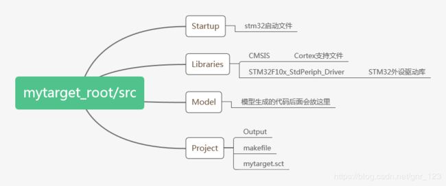
之前有讲过,在toolbox的根目录下,有一个src文件,用来放支撑模型运行的源代码。
mytargetroot/src
这个目录放喜闻乐见的C源码,例如启动、定时等运行框架代码,也包含硬件驱动的接口。
我准备的文件如下,熟悉STM32的朋友应该会看着比较眼熟,同时也会发现里面没有main.c。main.c我们会在代码生成的阶段把它生成出来,在开发阶段需要做的是编写一个生成的模板,这个生成的模板就是mytarget_proc.tlc。
mytarget_proc.tlc的内容看起来既熟悉又陌生,熟悉的是大段的C语言代码,陌生的是里面夹杂着少许TLC代码。它的主要功能是创建了一个新的源文件main.c,并通过LibGetMdlPubHdrBaseName、LibCallModelInitialize、LibCallModelStep、LibCallModelTerminate等几个TLC函数包含模型头文件,调用模型的initialize、step、terminate等函数。
%%%%%%%%%%%%%%%%%%%%%%%%%%%%%%%%%%%%%%%%%%%%%%%%%%%%%%%%%%%%%%%%%%%%%%%%%%%%%%%%%
%%
%% Abstract:
%%   MyTarget file processing.
%%
%%
%%%%%%%%%%%%%%%%%%%%%%%%%%%%%%%%%%%%%%%%%%%%%%%%%%%%%%%%%%%%%%%%%%%%%%%%%%%%%%%%%
%selectfile NULL_FILE
%assign ERTCustomFileTest = TLC_TRUE

%if EXISTS("ERTCustomFileTest") && ERTCustomFileTest == TLC_TRUE && !IsModelReferenceTarget()
  %<LibSetCodeTemplateComplianceLevel(1)>
  %if GenerateSampleERTMain
    %assign CompliedModel.GenerateSampleERTMain = TLC_FALSE
  %endif
  %assign cFile = LibCreateSourceFile("Source", "Custom", "main")

  %openfile typesBuf

  /* Includes ------------------------------------------------------------------*/
#include "stm32f10x.h"
#include "rtwtypes.h"
#include "%.h"
  %closefile typesBuf
  %<LibSetSourceFileSection(cFile,"Includes",typesBuf)>
   %openfile tmpBuf


volatile unsigned long systemTick;
void GPIO_Config(void);

#define Now()  systemTick

struct timer
{
    unsigned long period;
    unsigned long timeout;
};

struct timer periodTimer;

struct led
{
    GPIO_TypeDef *port;
    unsigned short pin;
};

static struct led ledConfig[4] =
{
  {GPIOB, (((unsigned short)1)<<8)},
  {GPIOB, (((unsigned short)1)<<9)},
  {GPIOE, (((unsigned short)1)<<0)},
  {GPIOE, (((unsigned short)1)<<1)},
};

void LedContrl(unsigned char nr, unsigned char state)
{
    if (state == 1)
    {
      GPIO_ResetBits(ledConfig[nr].port,ledConfig[nr].pin);
    }
    else
    {
      GPIO_SetBits(ledConfig[nr].port,ledConfig[nr].pin);
    }
}

/**
  * @brief  Main program.
  * @param  None
  * @retval : None
  */
int main(void)
{
  systemTick = 0;
	/* Setup STM32 system (clock, PLL and Flash configuration) */
	SystemInit();
	GPIO_Config();

	/* Setup SysTick Timer for 1 msec interrupts  */
  	if (SysTick_Config(72000000 / 1000)){
    	/* Capture error */
    	while (1);
  	}

    /* Initialize model */
    %<LibCallModelInitialize()>

  periodTimer.period = 10;
  periodTimer.timeout = Now() + periodTimer.period;
	/* Infinite loop */
	while (1) {

    if (Now()>periodTimer.timeout)
    {
      periodTimer.timeout = Now() + periodTimer.period;
      %<LibCallModelStep(0)>
    }


	}
    %<LibCallModelTerminate()>
}

/**
  * @brief  GPIO_Config program.
  * @param  None
  * @retval : None
  */
void GPIO_Config(void)
{
  GPIO_InitTypeDef GPIO_InitStructure;

  RCC_APB2PeriphClockCmd(RCC_APB2Periph_GPIOA | RCC_APB2Periph_GPIOB | RCC_APB2Periph_GPIOC |
                         RCC_APB2Periph_GPIOD | RCC_APB2Periph_GPIOE | RCC_APB2Periph_AFIO, ENABLE);

/**
 *	LED1 -> PB8	,	LED2 -> PB9 , LED3 -> PE0 , LED4 -> PE1
 */
  GPIO_InitStructure.GPIO_Pin = GPIO_Pin_8 |GPIO_Pin_9;
  GPIO_InitStructure.GPIO_Speed = GPIO_Speed_50MHz;
  GPIO_InitStructure.GPIO_Mode = GPIO_Mode_Out_PP;
  GPIO_Init(GPIOB, &GPIO_InitStructure);

  GPIO_InitStructure.GPIO_Pin = GPIO_Pin_0 |GPIO_Pin_1;
  GPIO_InitStructure.GPIO_Speed = GPIO_Speed_50MHz;
  GPIO_InitStructure.GPIO_Mode = GPIO_Mode_Out_PP;
  GPIO_Init(GPIOE, &GPIO_InitStructure);

}
#ifdef  USE_FULL_ASSERT

/**
  * @brief  Reports the name of the source file and the source line number
  *   where the assert_param error has occurred.
  * @param file: pointer to the source file name
  * @param line: assert_param error line source number
  * @retval : None
  */
void assert_failed(uint8_t* file, uint32_t line)
{
  /* User can add his own implementation to report the file name and line number,
     ex: printf("Wrong parameters value: file %s on line %d\r\n", file, line) */

  /* Infinite loop */
  while (1)
  {
  }
}
#endif

/**
  * @}
  */

  %closefile tmpBuf
%<LibSetSourceFileSection(cFile,"Functions",tmpBuf)>
%endif
在模型生成后,mytargetroot/src目录下应当是一个完整的可编译的STM32工程,这个工程不是指Keil工程,为了实现在代码生成后的自动化编译,我们编写makefile文件,让matlab来启动编译。
MAKE = C:\TDM-GCC-64\bin\make
KEIL_PATH = C:\Keil\ARM

ARMCC = $(KEIL_PATH)\BIN40\armcc
ARMASM = $(KEIL_PATH)\BIN40\armasm
ARMAR = $(KEIL_PATH)\BIN40\armar
ARMLINK = $(KEIL_PATH)\BIN40\armlink
FROMELF = $(KEIL_PATH)\BIN40\fromelf

CFLAGS := -c --cpu Cortex-M3 -D__MICROLIB -g -O0 --apcs=interwork
CMACRO := -DSTM32F10X_HD -DUSE_STDPERIPH_DRIVER
ASMFLAGS := --cpu Cortex-M3 -g --apcs=interwork --pd "__MICROLIB SETA 1"
LINKFLAGS := --cpu Cortex-M3 --library_type=microlib --strict
MAP := --autoat --summary_stderr --info summarysizes --map --xref --callgraph --symbols
INFO := --info sizes --info totals --info unused --info veneers

TARGET = .\Output\mytarget
OBJMAP := .\Output\*.map
OBJHTM := .\Output\*.htm
OBJAXF := .\Output\*.axf

SRCS = ..\User\src\main.c

OBJS = ..\Model\main.o\
       ..\Startup\startup_stm32f10x_hd.o\
	   ..\Libraries\CMSIS\core_cm3.o\
	   ..\Libraries\CMSIS\system_stm32f10x.o\
	   ..\Libraries\CMSIS\stm32f10x_it.o


INC += -I$(KEIL_PATH)\RV31\INC
INC += -I$(KEIL_PATH)\CMSIS\Include
INC += -I$(KEIL_PATH)\INC\ST\STM32F10x
INC += -I..\Libraries\CMSIS
INC += -I..\Libraries\STM32F10x_StdPeriph_Driver\inc

%.o:%.c
	$(ARMCC) $(CFLAGS) $(INC) $(CMACRO) $< -o $@

%.o:%.s
	$(ARMASM) $(ASMFLAGS) $(INC) $< -o $@

mytarget:$(OBJS)
	$(ARMLINK) $(LINKFLAGS) --libpath "$(KEIL_PATH)\RV31\LIB" --scatter=mytarget.sct $(MAP) $(INFO) --list $(TARGET).map $^ ..\Libraries\STM32F10xR_V3.0.lib --output=$(TARGET).axf
	$(FROMELF) --bin -o $(TARGET).bin $(TARGET).axf
	$(FROMELF) --i32 -o $(TARGET).hex $(TARGET).axf
	del $(OBJHTM) $(OBJAXF) $(OBJS)

.PHONY : clean

clean:
	del $(OBJS) *.map *.htm
回想上次的ConfigureMyTarget模块,我们并没有为它编写TLC文件,这会导致在模型代码生成过程中需要支持noninlined S-Functions,依赖non-finite numbers和floating-point numbers,从而生成例如rtGetIf.c等多个C文件,为了避免生成我们不想要的文件,给ConfigureMyTarget模块编写如下TLC。
%implements "ConfigureMyTarget" "C"

%function BlockTypeSetup(block, system) Output

%endfunction

%function Start(block, system) Output

%endfunction

%function Outputs(block, system) Output

%endfunction
下面我们来验证一下,建立一个模型,模型名字叫demo,里面什么都没有,只是放了一个配置模型的模块。
 双击配置模型,然后Build,模型代码和main.c文件按照预期生成。
 ok,这次就到这里,下次我们来看如何自动化的编译生成的文件。
