verilog入门
- 做一个4选1的mux,并且进行波形仿真和2选1的mux对比,观察资源消耗的变化
// module  41, 选择器(mux)的代码,
module mux41(
  IN0       ,   // input 1
  IN1       ,   // input 2
  IN2       ,   // input 3
  IN3       ,   // input 4
  SEL       ,   // select
  OUT       );  // out data
parameter WL = 16;      // 输入输出数据信号位宽
input [WL-1:0] IN0,IN1,IN2,IN3;// 选择器的四个输入数据信号
input [1:0] SEL;              // 通道选通的控制信号
output[WL-1:0] OUT;     // 选择器的输入数据信号

reg   [WL-1:0] OUT;
// 生成组合逻辑的代码
always @ (IN0 or IN1 or IN2 or IN3 or SEL) begin
  if(SEL ==2'b00) // SEL为00 选择输0
    OUT = IN0;
  else if(SEL ==2'b01)    // SEL为01 选择输入1
    OUT = IN1;
  else if(SEL ==2'b10)    // SEL为10 选择输入2
    OUT = IN2;
  else     // SEL为11 选择输入3
    OUT = IN3;
end
endmodule
// endmodule top
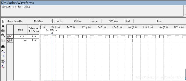
波形仿真:

资源消耗对比:
mux4_1:
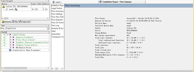
mux2_1:

mux4_1比mux2_1的logic_cell多一倍,即资源消耗多了将近一倍。
- 编写一个4X4路交叉开关的RTL,然后编译,看RTL View 比较2x2与4x4之间消耗资源的区别。通过对比资源,你有什么结论?
// module  top, a 4x4 crossbar switch circuit

module mux44(
  IN0       ,   // input 1
  IN1       ,   // input 2
  IN2       ,   // input 3
  IN3       ,   // input 4
  SEL0      ,   // select the output0 source
  SEL1      ,   // select the output1 source
  SEL2      ,   // select the output2 source
  SEL3      ,   // select the output3 source
  OUT0      ,   // output data 0
  OUT1      ,   // output data 1
  OUT2      ,   // output data 2
  OUT3      );  // output data 3
parameter WL = 16;
input [WL-1:0] IN0, IN1, IN2,IN3;
input SEL0, SEL1, SEL2, SEL3;
output[WL-1:0] OUT0, OUT1, OUT2, OUT3;

reg   [WL-1:0] OUT0, OUT1, OUT2, OUT3;
// get the OUT0
always @ (IN0 or IN1 or IN2 or IN3 or SEL0 or SEL1) begin
  if((SEL0)&&(SEL1))
    OUT0 = IN3;
  else if((!SEL0)&&(SEL1))
    OUT0 = IN2;
  else if((SEL0)&&(!SEL1))
    OUT0 = IN1;
  else
    OUT0 = IN0;
end
// get the OUT1
always @ (IN0 or IN1 or IN2 or IN3 or SEL1 or SEL2) begin
  if((SEL1)&&(SEL2))
    OUT1 = IN3;
  else if((!SEL1)&&(SEL2))
    OUT1 = IN2;
  else if((SEL1)&&(!SEL2))
    OUT1 = IN1;
  else
    OUT1 = IN0;
end
// get the OUT2
always @ (IN0 or IN1 or IN2 or IN3 or SEL2 or SEL3) begin
  if((SEL2)&&(SEL3))
    OUT2 = IN3;
  else if((!SEL2)&&(SEL3))
    OUT2 = IN2;
  else if((SEL2)&&(!SEL3))
    OUT2 = IN1;
  else
    OUT2 = IN0;
end
// get the OUT3
always @ (IN0 or IN1 or IN2 or IN3 or SEL0 or SEL3) begin
  if((SEL0)&&(SEL3))
    OUT3 = IN3;
  else if((!SEL0)&&(SEL3))
    OUT3 = IN2;
  else if((SEL0)&&(!SEL3))
    OUT3 = IN1;
  else
    OUT3 = IN0;
end
endmodule
// endmodule top
RTL View:

消耗资源对比:
4x4:
2x2:

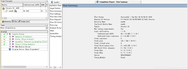
2x2的交叉开关是2个输出分别对应1个1位的控制信号,选择该输出哪一个输入信号,4X4路的交叉开关,则每个输出对应一个2位的控制信号,从四个输入信号中选择一个进行输出,当输入和输出的端口增加时,该电路会消耗非常多的电路资源,4x4的交叉开关消耗资源成倍的增长了。
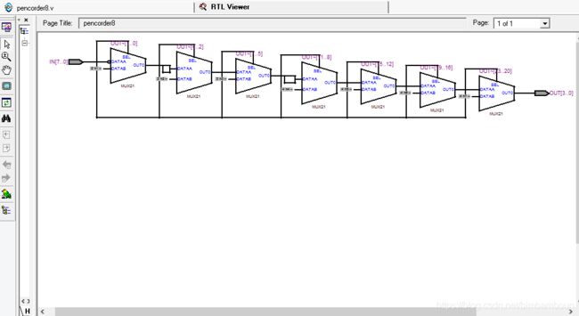
- 编写一个8输入的优先编码器,然后编译,看RTL View
module pencorder8(
  IN        ,   // input
  OUT       );  // output
input [7:0] IN;
output[3:0] OUT;

reg   [3:0] OUT;
// get the OUT
always @ (IN) begin
   if(IN[7])       // 第一优先
     OUT = 4'b0111;
   else if(IN[6])  // 第二优先
     OUT = 4'b0110;
   else if(IN[5])  // 第三优先
     OUT = 4'b0101;
   else if(IN[4])  // 第四优先
     OUT = 4'b0100;
   else if(IN[3])  // 第5
     OUT = 4'b0011;
   else if(IN[2])  // 6
     OUT = 4'b0010;
   else if(IN[1])  // 7
     OUT = 4'b0001;
   else if(IN[0])  // 8
     OUT = 4'b0000;
   else            // 什么都没有检测到
     OUT = 4'b1111; // 输出值可自定义,不和上面的输出值混淆即可
end
endmodule
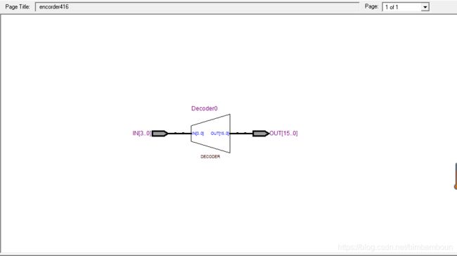
- 编写一个4-16的译码器,编译
- 和3-8译码器对比资源开销
- 看RTL View
module encorder416(
  IN        ,   // input
  OUT       );  // output

input [3:0] IN;
output[15:0] OUT;

reg   [15:0] OUT;
// get the OUT
always @ (IN) begin
  case(IN)
    4'b0000: OUT = 16'b0000_0000_0000_0001;
    4'b0001: OUT = 16'b0000_0000_0000_0010;
    4'b0010: OUT = 16'b0000_0000_0000_0100;
    4'b0011: OUT = 16'b0000_0000_0000_1000;
    4'b0100: OUT = 16'b0000_0000_0001_0000;
    4'b0101: OUT = 16'b0000_0000_0010_0000;
    4'b0110: OUT = 16'b0000_0000_0100_0000;
    4'b0111: OUT = 16'b0000_0000_1000_0000;
    4'b1000: OUT = 16'b0000_0001_0000_0000;
    4'b1001: OUT = 16'b0000_0010_0000_0000;
    4'b1010: OUT = 16'b0000_0100_0000_0000;
    4'b1011: OUT = 16'b0000_1000_0000_0000;
    4'b1100: OUT = 16'b0001_0000_0000_0000;
    4'b1101: OUT = 16'b0010_0000_0000_0000;
    4'b1110: OUT = 16'b0100_0000_0000_0000;
    4'b1111: OUT = 16'b1000_0000_0000_0000;
    //  full case 不需要写default,否则一定要有default
  endcase
end
endmodule
消耗资源对比:
4-16译码器:
3-8译码器:
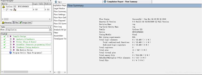
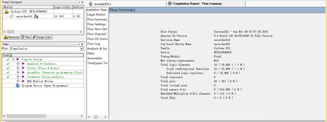
输入输出增加一位,4-16译码器的消耗资源几乎比3-8译码器的消耗资源多了一倍。
- 无符号加法器:输入和输出数据都是无符号的整数
- 把加法器的输出信号改成4比特位宽,编译,波形仿真。观察输出结果,说出输出和输入的对应关系。
- 把加法器的输入信号改成8比特位宽,编译,波形仿真。观察加法器的输出延迟,和4比特输入位宽的情况对比,你有什么结论,为什么?
4比特宽输出:
module unadd4(
  IN1   ,
  IN2   ,
  OUT   );
input[3:0] IN1, IN2;
output[3:0] OUT;
reg[3:0] OUT;
always@(IN1 or IN2) begin // 生成组合逻辑的always 块
  OUT = IN1 + IN2;
end
endmodule
仿真波形:

结果分析:原实验是4位输入、5位输出的的无符号加法器,结果不会超出量程,而改为4位输出,输出结果最大为15,超出量程则会出错,仅能输出正确结果的后四位。
8比特宽输入:
module unadd8(
  IN1   ,
  IN2   ,
  OUT   );
input[7:0] IN1, IN2;
output[4:0] OUT;
reg[4:0] OUT;
always@(IN1 or IN2) begin // 生成组合逻辑的always 块
  OUT = IN1 + IN2;
end
endmodule
仿真波形:
结果分析:
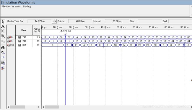
改为8位输入(0~255),5位输出,输出量程为0至31,则超出量程的部分只能输出正确结果的后5位,而加法器仍然需要运算正确结果的前3位,所以输出延时应该要大于4位输入、5位输出的加法器。
- 补码加法器:输入和输出数据都是2补码形式的有符号数
- 把加法器的输出信号改成4比特位宽,编译,波形仿真。观察输出结果,观察输出结果在什么时候是正确的? 把加法器的输入信号改成8比特位宽,编译,波形仿真。观察加法器的输出延迟,和4比特输入位宽的情况对比,你有什么结论,为什么?
4比特输出:
module sigadd4(
  IN1   ,
  IN2   ,
  OUT   );
input signed [3:0] IN1, IN2;
output signed [4:0] OUT;
reg signed [4:0] OUT;
always@(IN1 or IN2) begin // 生成组合逻辑的always 块
  OUT = IN1 + IN2;
end
endmodule
8比特输入:
module sigadd8(
  IN1   ,
  IN2   ,
  OUT   );
input signed [7:0] IN1, IN2;
output signed [4:0] OUT;
reg signed [4:0] OUT;
always@(IN1 or IN2) begin // 生成组合逻辑的always 块
  OUT = IN1 + IN2;
end
endmodule
时序仿真:
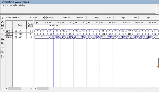
4比特输入:
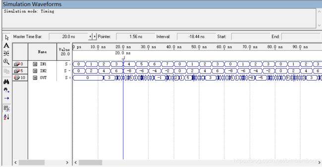
结果分析:和4比特输入相比,延时稍大一点。
- 不改变流水线的级数,把加法器的输入信号改成8比特位宽,编译,波形仿真,和不带流水线的情况对比一下,你有什么结论? 在8比特输入位宽的情况下,在输入上再添加一级流水线,观察编译和仿真的结果,你有什么结论?
8比特输入:
module fluadd(
  IN1   ,
  IN2   ,
  CLK   ,
  OUT   );
input  [7:0] IN1, IN2;
input CLK;
output  [4:0] OUT;
reg [7:0] in1_d1R, in2_d1R;
reg  [4:0] adder_out, OUT;
always@(posedge CLK) begin // 生成D触发器的always块
  in1_d1R <= IN1;
  in2_d1R <= IN2;
  OUT     <= adder_out;
end
always@(in1_d1R or in2_d1R) begin // 生成组合逻辑的always 块
  adder_out = in1_d1R + in2_d1R;
end
endmodule
仿真:

结果分析:与不加流水线的加法器相比,带流水线的加法器即在加法器的输入与输出都连接了D触发器,有效的减少了组合逻辑的竞争与冒险,从而明显减少了“毛刺”的长度。
再加一级流水线:
module fluadd1(
  IN1   ,
  IN2   ,
  CLK   ,
  OUT   );
input  [3:0] IN1, IN2;
input CLK;
output  [4:0] OUT;
reg [3:0] in1_d1R, in1_d2R, in2_d1R, in2_d2R;
reg  [4:0] adder_out, OUT;
always@(posedge CLK) begin // 生成D触发器的always块
  in1_d1R <= IN1;
  in2_d1R <= IN2;
  in1_d2R <= in1_d1R;
  in2_d2R <= in2_d1R;
  OUT     <= adder_out;
end
always@(in1_d2R or in2_d2R) begin // 生成组合逻辑的always 块
  adder_out = in1_d2R + in2_d2R;
end
endmodule
仿真:
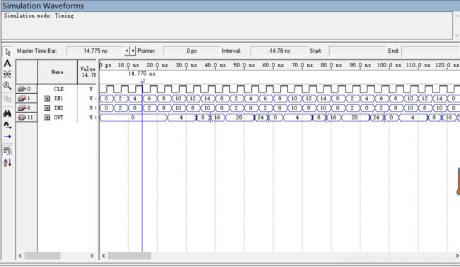
结果分析:流水线的级数越高,毛刺也随之越短,但输出的时延也会相应地增加。
- 乘法器:乘法器是一种奢侈品会消耗大量的组合电路逻辑资源。
- 改变乘法器的输入位宽为8比特,编译,波形仿真,观察信号毛刺的时间长度。
- 选一款没有硬件乘法器的FPGA芯片(例如Cyclone EP1C6)对比8比特的乘法器和加法器两者编译之后的资源开销(Logic Cell的数目)
- 编写一个输入和输出都有D触发器的流水线乘法器代码,编译后波形仿真,观察组合逻辑延迟和毛刺的时间,和不带流水线的情况下对比。
8比特输入:
////////////////////  无符号的乘法器  /////////////////////////
module unmul8(
  IN1   ,
  IN2   ,
  OUT   );
 input [7:0] IN1, IN2;
 output [7:0] OUT;
 reg [7:0] OUT;
always@(IN1 or IN2) begin // 生成组合逻辑的always 块
  OUT = IN1 * IN2;
end
endmodule
仿真:

资源消耗对比:

无硬件:

结果分析:无硬件的logic cell明显更多,资源消耗更大。
流水线乘法器:
module flumul8(
  IN1   ,
  IN2   ,
  CLK   ,
  OUT   );
 input signed[3:0] IN1, IN2;
 input CLK;
 output signed [7:0] OUT;

 reg signed[7:0] mulout, OUT;
 reg signed[3:0] in1_d1R, in2_d1R;
always@(posedge CLK) begin // 生成always 块
  in1_d1R <=IN1;
  in2_d1R <=IN2;
  OUT <= mulout;
end
 always@(in1_d1R or in2_d1R) begin // 生成组合逻辑的always 块
  mulout = in1_d1R * in2_d1R;
end
endmodule
仿真:

结果分析:相比于没有流水线的乘法器,毛刺时间变短,延时变长。
- 设计一个最简单的计数器,只有一个CLK输入和一个OVerflow输出,当计数到最大值的时钟周期CLK输出1
- 设计复杂的计数器,和本例相似,带有多种信号,其中同步清零CLR的优先级最高,使能EN次之,LOAD最低。
简单计数器:
//////////////////// 计数器代码  /////////////////////////

module counter(
  CLK   , // 时钟,上升沿有效
  OVerflow    );// 计数溢出信号,计数值为最大值时该信号为1

input  CLK;
output OVerflow;

reg OVerflow;
reg [3:0] cnt_next;
// 电路编译参数,最大计数值
parameter CNT_MAX_VAL = 9;

// 组合逻辑,生成OV
always @ (posedge CLK) begin
  if(cnt_next <= CNT_MAX_VAL) begin
    OVerflow <= 0;
    cnt_next <=cnt_next+1;
  end
  else begin
    OVerflow <= 1;
    cnt_next <=0;
  end
end

endmodule
复杂计数器:
//////////////////// 计数器代码  /////////////////////////

module counter1(
  RST   , // 异步复位, 高有效
  CLK   , // 时钟,上升沿有效
  EN    , // 输入的计数使能,高有效
  CLR   , // 输入的清零信号,高有效
  LOAD  , // 输入的数据加载使能信号,高有效
  DATA  , // 输入的加载数据信号
  CNTVAL, // 输出的计数值信号
  OV    );// 计数溢出信号,计数值为最大值时该信号为1

input RST   , CLK   , EN    , CLR   , LOAD  ;
input [3:0] DATA ;
output [3:0] CNTVAL;
output OV;

reg [3:0] CNTVAL, cnt_next;
reg OV;
// 电路编译参数,最大计数值
parameter CNT_MAX_VAL = 9;

// 组合逻辑,生成cnt_next
// CLR EN LOAD
always @(EN or CLR or LOAD or DATA or CNTVAL) begin
  if(CLR)    //CLR有效
    cnt_next=0;
  else begin
    if(EN) begin    //使能有效
      if(LOAD) begin // 加载有效
        cnt_next = DATA;
      end
      else begin     // 加载无效,正常计数
        if(CNTVAL < CNT_MAX_VAL) begin // 未计数到最大值, 下一值加1
          cnt_next = CNTVAL + 1'b1;
        end
        else begin // 计数到最大值,下一计数值为0
          cnt_next = 0;
        end
      end // else LOAD
    end
    else begin  // 使能无效,计数值保持不动
       cnt_next = CNTVAL;
    end // else EN
  end
end

// 时序逻辑 更新下一时钟周期的计数值
// CNTVAL 会被编译为D触发器
always @ (posedge CLK or posedge RST) begin
  if(RST)
    CNTVAL <= 0;
  else
    CNTVAL <= cnt_next;
end

// 组合逻辑,生成OV
always @ (CNTVAL) begin
  if(CNTVAL == CNT_MAX_VAL)
    OV = 1;
  else
    OV = 0;
end

endmodule
仿真:

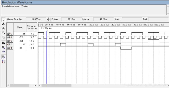
结果分析:当RST为复位,CLR输入清0,优先级比EN高,EN为1时,开始计数,当计数值为9时输出1,十进制计数,LOAD优先级最小,当LOAD为1时,将DATA输给计数值,当计数值数到为9时,输出1。
- 设计一个用于识别2进制序列“1011”的状态机:
- 电路每个时钟周期输入1比特数据,当捕获到1011的时钟周期,电路输出1,否则输出0
- 使用序列101011010作为输出的测试序列
- 给你的电路添加输入使能端口,只有输入使能EN为1的时钟周期,才从输入的数据端口向内部获取1比特序列数据。
////////////////////  三段式状态机代码  /////////////////////////
////////////////////  三段式状态机代码  /////////////////////////
module tinout(
  CLK       ,   // clock
  EN        ,
  RST       ,   // reset
  CENT1IN   ,   // input 1 cent coin
  TINOUT    );  // output 1 tin cola

input EN         ;
input  CLK       ;
input  RST       ;
input  CENT1IN   ;
output TINOUT    ;

parameter ST_0_CENT = 0;
parameter ST_1_CENT = 1;
parameter ST_2_CENT = 2;
parameter ST_3_CENT = 3;
parameter ST_4_CENT = 4;

reg [4-2:0]stateR       ;
reg [4-2:0]next_state   ;
reg        TINOUT       ;

// calc next state
always @ (EN or CENT1IN or stateR) begin
 if(EN) begin
  case (stateR)
    ST_0_CENT :begin if(CENT1IN) next_state = ST_1_CENT ; else next_state = ST_0_CENT; end
    ST_1_CENT :begin if(CENT1IN) next_state = ST_1_CENT ; else next_state = ST_2_CENT; end
    ST_2_CENT :begin if(CENT1IN) next_state = ST_3_CENT ; else next_state = ST_0_CENT; end
    ST_3_CENT :begin if(CENT1IN) next_state = ST_4_CENT ; else next_state = ST_2_CENT; end
    ST_4_CENT :begin next_state = ST_1_CENT; end
  endcase
 end
 else begin
  next_state = stateR;
 end
end

// calc output
always @ (stateR or CENT1IN) begin
  if(stateR == ST_4_CENT)
//  if((stateR == ST_3_CENT)&&(CENT1IN))
    TINOUT = 1'b1;
  else
    TINOUT = 1'b0;
end

// state DFF
always @ (posedge CLK or posedge RST)begin
  if(RST)
    stateR <= ST_0_CENT;
  else
    stateR <= next_state;
end

endmodule
仿真:
Tools-Netlist Viewers-State Machine Viewer 状态机转移图:

- 设计一个如本节“电路描述”部分的“带加载使能和移位使能的并入串出”的移位寄存器,电路的RTL结构图如“电路描述”部分的RTL结构图所示。
//////////////////// 串入并出移位寄存器  /////////////////////////
module yiwei(
  RST   ,   // 异步复位, 高有效
  CLK   ,   // 时钟,上升沿有效
  LOAD  ,
  EN    ,   // 输入数据串行移位使能
  IN    ,   // 输入串行数据
  OUT   );  // 并行输出数据

input RST, CLK, EN, LOAD;
input [3:0] IN;
output OUT;
reg [3:0] shift_R;
reg OUT;

//assign OUT[3:0] = shift_R[3:0];
// 时序逻辑 根据输入使能进行串行移位
// shift_R 会被编译为D触发器
always @ (posedge CLK or posedge RST) begin
  if(RST)
    shift_R[3:0] <= 0;
  else begin
    if(LOAD) begin
      shift_R[3:0] <=IN[3:0];
    end//load
    else begin
     if(EN) begin
      OUT=shift_R[3];
      shift_R[3:1] <= shift_R[2:0];
      shift_R[0]   <= 0;
     end
     else begin // 使能无效保持不动
      shift_R[3:0] <= shift_R[3:0];
     end
    end
  end
end // always
endmodule
RTL View:

仿真:

结果分析:
“并入串出”是将输入并行输入寄存器中,若移位使能有效,则将最高位输出,移位寄存器后三3同时前移1位,最低位存入0。设置RST为复位,LOAD是加载输入的使能端,EN是移位使能端,当LOAD为1时,加载输入,当EN=1时,进行移位,将最高位shift_R[3]输出。
