FIR Filter Design
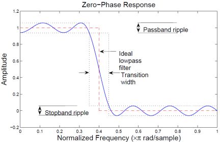
The ideal lowpass filter is one that leaves unchanged all frequency components of a signal below a designated cutoff frequency, ωc, and rejects all components above ωc. Because the impulse response required to implement the ideal lowpass filter is infinitely long, it is impossible to design an ideal FIR lowpass filter. Finite length approximations to the ideal impulse response lead to the presence of ripples in both the passband (ω<ωc) and the stopband (ω>ωc) of the filter, as well as to a nonzero transition width between passband and stopband.
Both the passband/stopband ripples and the transition width are undesirable but unavoidable deviations from the response of an ideal lowpass filter when approximated with a finite impulse response. These deviations are depicted in the following figure:
Practical FIR designs typically consist of filters that have a transition width and maximum passband and stopband ripples that do not exceed allowable values. In addition to those design specifications, one must select the filter order, or, equivalently, the length of the truncated impulse response.
A useful metaphor for the design specifications in filter design is to think of each specification as one of the angles in the triangle shown in the figure below.
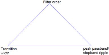
The triangle is used to understand the degrees of freedom available when choosing design specifications. Because the sum of the angles is fixed, one can at most select the values of two of the specifications. The third specification will be determined by the particular design algorithm. Moreover, as with the angles in a triangle, if we make one of the specifications larger/smaller, it will impact one or both of the other specifications.
FIR filters are very attractive because they are inherently stable and can be designed to have linear phase. Nonetheless, these filters can have long transient responses and might prove computationally expensive in certain applications.
Minimum-Order FIR Designs
Minimum-order designs are obtained by specifying passband and stopband frequencies as well as a passband ripple and a stopband attenuation. The design algorithm then chooses the minimum filter length that complies with the specifications.
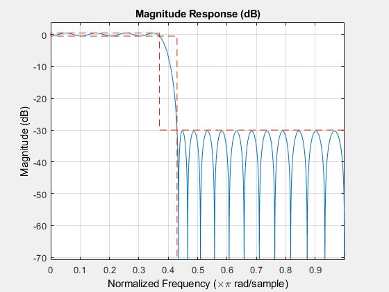
Design a minimum-order lowpass FIR filter with a passband frequency of 0.37*pi rad/sample, a stopband frequency of 0.43*pi rad/sample (hence the transition width equals 0.06*pi rad/sample), a passband ripple of 1 dB and a stopband attenuation of 30 dB.
Fpass = 0.37;
Fstop = 0.43;
Ap = 1;
Ast = 30;

d = designfilt('lowpassfir','PassbandFrequency',Fpass,...
  'StopbandFrequency',Fstop,'PassbandRipple',Ap,'StopbandAttenuation',Ast);
The resulting filter order can be queried using the filtord function.
N = filtord(d)
N = 39
Thedesignfiltfunction chooses an equiripple design algorithm by default. Linear-phase equiripple filters are desirable because for a given order they have the smallest possible maximum deviation from the ideal filter.
Note, however, that minimum-order designs can also be obtained using a Kaiser window. Even though the Kaiser window method yields a larger filter order for the same specifications, the algorithm is less computationally expensive and less likely to have convergence issues when the design specifications are very stringent. This may occur if the application requires a very narrow transition width or a very large stopband attenuation.
Design a filter with the same specifications as above using the Kaiser window method and compare its response to the equiripple filter.
dk = designfilt('lowpassfir','PassbandFrequency',Fpass,...
  'StopbandFrequency',Fstop,'PassbandRipple',Ap,...
  'StopbandAttenuation',Ast, 'DesignMethod', 'kaiserwin');

N = filtord(dk)
N = 52
Specifying Frequency Parameters in Hertz
If you know the sample rate at which the filter will operate, you can specify the sample rate and the frequencies in hertz. Redesign the minimum-order equiripple filter for a sample rate of 2 kHz.
Fpass = 370;
Fstop = 430;
Ap = 1;
Ast = 30;
Fs = 2000;

d = designfilt('lowpassfir','PassbandFrequency',Fpass,...
  'StopbandFrequency',Fstop,'PassbandRipple',Ap,...
  'StopbandAttenuation',Ast,'SampleRate',Fs);

Fixed Order, Fixed Transition Width
Fixed-order designs are useful for applications that are sensitive to computational load or impose a limit on the number of filter coefficients. An option is to fix the transition width at the expense of control over the passband ripple/stopband attenuation.
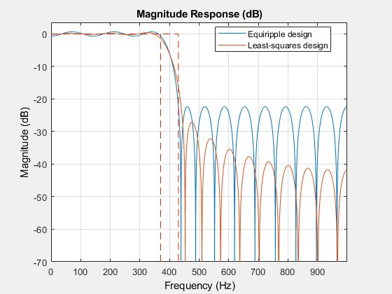
Consider a 30-th order lowpass FIR filter with a passband frequency of 370 Hz, a stopband frequency of 430 Hz, and sample rate of 2 kHz. There are two design methods available for this particular set of specifications: equiripple and least squares. Let us design one filter for each method and compare the results.
N = 30;
Fpass = 370;
Fstop = 430;
Fs = 2000;

% Design method defaults to 'equiripple' when omitted
deq = designfilt('lowpassfir','FilterOrder',N,'PassbandFrequency',Fpass,...
  'StopbandFrequency',Fstop,'SampleRate',Fs);

dls = designfilt('lowpassfir','FilterOrder',N,'PassbandFrequency',Fpass,...
  'StopbandFrequency',Fstop,'SampleRate',Fs,'DesignMethod','ls');
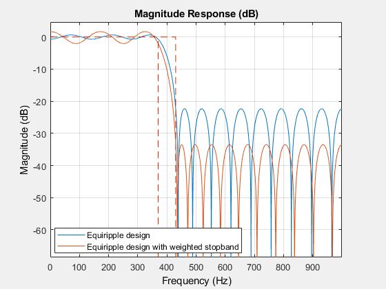
Equiripple filters are ideally suited for applications in which a specific tolerance must be met, such as designing a filter with a given minimum stopband attenuation or a given maximum passband ripple. On the other hand, these designs may not be desirable if we want to minimize the energy of the error (between ideal and actual filter) in the passband/stopband.
In the examples above, the designed filters had the same ripple in the passband and in the stopband. We can use weights to reduce the ripple in one of the bands while keeping the filter order fixed. For example, if you wish the stopband ripple to be a tenth of that in the passband, you must give the stopband ten times the passband weight. Redesign the equiripple filter using that fact.
deqw = designfilt('lowpassfir','FilterOrder',N,'PassbandFrequency',Fpass,...
  'StopbandFrequency',Fstop,'SampleRate',Fs,...
  'PassbandWeight',1,'StopbandWeight',10);
Fixed Order, Fixed Cutoff Frequency
You can design filters with fixed filter order and cutoff frequency using a window design method.
-
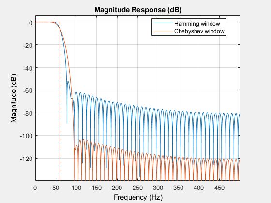
You can use different windows to control the stopband attenuation while keeping the filter order unchanged.
For example, consider a 100-th order lowpass FIR filter with a cutoff frequency of 60 Hz and a sample rate of 1 kHz. Compare designs that result from using a Hamming window, and a Chebyshev window with 90 dB of sidelobe attenuation.
dhamming = designfilt('lowpassfir','FilterOrder',100,'CutoffFrequency',60,...
  'SampleRate',1000,'Window','hamming');

dchebwin = designfilt('lowpassfir','FilterOrder',100,'CutoffFrequency',60,...
  'SampleRate',1000,'Window',{'chebwin',90});
There are other ways in which you can specify a filter with fixed order: fixed cutoff frequency, passband ripple, and stopband attenuation; fixed transition width; and fixed half-power (3dB) frequency.
Reference,
1. MathWorks