Stm32下的激光传输数据
做出来没有什么实际用途数据,传输速率不快..不过能够学到很多东西
原理
将数据使用Biphase mark coding(BMC)加码, 激光亮代表1灭代表0,使用接受器接收激光并解码
什么是BMC?
BMC是一种数据加码方式,有两种状态:
1.全周期固定反转,0变1,1变0
2.半周期基于数据反转,0不反转,1反转
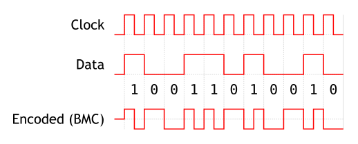
看下图应该会明白(图片来自维基百科)
不懂的带你走一下..
请看图片中的Encoded(BMC)这行
最开始的反转是全周期,全周期固定反转,0变1(它上面画的是中位,其实应该是低位)
之后是半周期,半周期按照数据反转,数据第一位是1,所以要反转
之后全周期,固定反转,低位变高位--第一bit的数据已经传输完毕
然后到了半周期,数据是0,不反转,保持高位
之后全周期,固定反转,高变低
....于是就有了上面那个图
具体介绍可以到维基百科看一下
http://en.wikipedia.org/wiki/Differential_Manchester_encoding
解码
激光可以传输数据,我们就可以用接收器分析并且解码
将D0与Tim3链接,设置触发为TIM_ICPolarity_BothEdge(上升沿和下降沿),这样每次触发就会读到这次触发和上次触发的时差
比如上面图的度数就会类似于
0.5 0.5 1 1 0.5 0.5 0.5 0.5 1 0.5 0.5 1 1 0.5 0.5,
数值的大小基于你tim3的频率,数值代表上一次触发和这一次触发tim3走过了多少tick,我在实验中半周期的度数是300tick左右,全周期大概在600tick左右
需要注意的是,不能够直接在激光中传输原始数据,因为解码程序不知道那里是开始与结束
所以这里用了按字节传输的方法,将数据用汉明加密,并且在每字节前面加上11,后面加上0
比如传入字节是0xff
汉明加密后变为两字节:
ffff --也就是 1111,1111, 1111,1111
然后在每字节前面和后面加上修饰位11和0,便成了
11,1111,1111,0 11,1111,1111,0
一个11,dddd,ddddd,0的组合是一个码块,可解码出4位原始数据
这样我们按照每个码块来传输,如果出现了错误,我们也可以知道下一个码块从哪里开始
关于汉明加密
汉明加密可以给予数据自我恢复的能力,这里使用的是8,4加密法, 4bit数据加密后将变为8bit
如果这8bit中有一位在传输过程中由于错误反转,在解码的时候也可以找出错误位并纠正
但是多余1位的错误是无法纠正的(不过几率很小)
具体请看wiki
http://en.wikipedia.org/wiki/Hamming_code
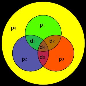
没接触过的可以看下这个图(图片来自维基百科)
d1到d4代表数据位,是原始的数据
p1到p4是校验位,根据原始数据算出的
如何算呢?看图可知,
p1 = d1^d2^d4
p2 = d1^d4^d3
p3 = d2^d3^d4
p4 = p1^p2^p3^d1^d2^d3^d4 也就是一个奇偶校验位
加密后,如果这8位其中任意一位反转,你都可以计算出反转位哪里(自我恢复能力).
实现
需要注意的是,真实读出来的时差并不是十分准确,不会像这样:
300,300,600,600,300
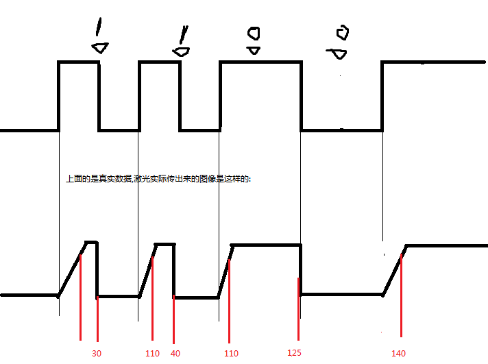
因为激光每次发光会有一个冲能时间,在冲能时间里,光缓慢变亮,只有亮到一定程度后才能够被捕获
看下图:
由于激光会冲能,高位的时候会有延迟,频率越高越干扰明显
红色的是读数半周期有: 30 110 40 110
全周期有 125 150
于是我们定义一个界限, 小与117的为半周期,大于117的为全周期
如果能够吧接受器灵敏度调高一些,这样的情况会有缓解
附上部分解码部分初始化和实现代码:
void hwInit_D0Tim3(){


	GPIO_InitTypeDef GPIO_InitStructure;

	TIM_ICInitTypeDef  TIM_ICInitStructure;

	NVIC_InitTypeDef   NVIC_InitStructure;
	TIM_TimeBaseInitTypeDef  TIM_TimeBaseStructure;


	uint16_t PrescalerValue = 0;


  	/* TIM3 clock enable */

  	RCC_APB1PeriphClockCmd(RCC_APB1Periph_TIM3, ENABLE);


  	/* Enable the D0 Clock */

  	RCC_AHB1PeriphClockCmd(NP2_D0_GPIO_CLK, ENABLE);


  	/* Configure the D0 pin */

  	GPIO_InitStructure.GPIO_Pin = NP2_D0_PIN;

  	GPIO_InitStructure.GPIO_Mode = GPIO_Mode_AF;

  	GPIO_InitStructure.GPIO_Speed = GPIO_Speed_100MHz;

  	GPIO_InitStructure.GPIO_OType = GPIO_OType_PP;

  	GPIO_InitStructure.GPIO_PuPd = GPIO_PuPd_UP ;

  	GPIO_Init(NP2_D0_GPIO_PORT, &GPIO_InitStructure);


  	/* Connect TIM3 output to D0 pin */

  	GPIO_PinAFConfig(NP2_D0_GPIO_PORT, NP2_D0_PINSOURCE, GPIO_AF_TIM3);


	//--Compute the prescaler value

  	PrescalerValue = (uint16_t) ((SystemCoreClock /2)/TIM3_PRESCALER) - 1;

  	//--Time base configuration

  	TIM_TimeBaseStructure.TIM_Period = TIM3_PERIOD;

  	TIM_TimeBaseStructure.TIM_Prescaler = PrescalerValue;

  	TIM_TimeBaseStructure.TIM_ClockDivision = 0;

  	TIM_TimeBaseStructure.TIM_CounterMode = TIM_CounterMode_Up;

  	TIM_TimeBaseInit(TIM3, &TIM_TimeBaseStructure);


	// Configure TIM3 Input capture for channel 2

  	TIM_ICInitStructure.TIM_Channel = TIM_Channel_2;

  	TIM_ICInitStructure.TIM_ICPolarity = TIM_ICPolarity_BothEdge;

  	TIM_ICInitStructure.TIM_ICSelection = TIM_ICSelection_DirectTI;

  	TIM_ICInitStructure.TIM_ICPrescaler = TIM_ICPSC_DIV1;

  	TIM_ICInitStructure.TIM_ICFilter = 0x0;


	TIM_ICInit(TIM3, &TIM_ICInitStructure);


	TIM_UpdateRequestConfig(TIM3,TIM_UpdateSource_Regular);

	// Select the TIM3 Filter Input Trigger: TI2FP2

  	TIM_SelectInputTrigger(TIM3, TIM_TS_TI2FP2);


	/* Enable the TIM3 global Interrupt */

  	NVIC_InitStructure.NVIC_IRQChannel = TIM3_IRQn;

  	NVIC_InitStructure.NVIC_IRQChannelPreemptionPriority = 0;

  	NVIC_InitStructure.NVIC_IRQChannelSubPriority = 1;

  	NVIC_InitStructure.NVIC_IRQChannelCmd = ENABLE;

  	NVIC_Init(&NVIC_InitStructure);


  	/* Select the slave Mode: Reset Mode */

  	TIM_SelectSlaveMode(TIM3, TIM_SlaveMode_Reset);

  	TIM_SelectMasterSlaveMode(TIM3,TIM_MasterSlaveMode_Enable);


  	/* Enable the CC2 Interrupt Request */

  	TIM_ITConfig(TIM3, TIM_IT_CC2, ENABLE);

	//enable overflow flag
	//TIM_ITConfig(TIM3, TIM_IT_Update, ENABLE);


	//clear overflow flag
	TIM_ClearFlag(TIM3, TIM_FLAG_Update);

	//disable arp preload
	//TIM_ARRPreloadConfig(TIM3, DISABLE);


  	/* TIM3 enable counter */

 	TIM_Cmd(TIM3, ENABLE);
}
void TIM3_IRQHandler(void) {

//bug: if data is continuous (without idle time) then any error will lead to infinate wait state

	uint16_t read_value;


	if (TIM_GetITStatus(TIM3, TIM_IT_CC2) != RESET) {

    		TIM_ClearITPendingBit(TIM3, TIM_IT_CC2);
		laser_recv_ttl = 10;
		read_value = TIM_GetCapture2(TIM3);
		//debug_printf("readval = %d\r\n", read_value);

		if (  TIM_GetFlagStatus(TIM3,TIM_FLAG_Update) == SET || read_value > full_idle_gate ){
			//overflow or idle end state, reset counter..
			TIM_ClearFlag(TIM3,TIM_FLAG_Update);
			read_enc_hchar = 0;
			//hbyte_counter = 0;
			rx_bit_counter = 0;
			last_state = PERIOD_FULL;
			//debug_printf("idle end\r\n");
			return;//idle end
		}

		if ( last_state == PERIOD_FULL ){

			if ( read_value < half_full_gate ){
				//last state is full, interval is half, this state is half, read 1
				rx_bit_counter++;
				if ( rx_bit_counter != 1 && rx_bit_counter != 2 && rx_bit_counter != 11 ){
					read_enc_hchar = read_enc_hchar << 1;
					read_enc_hchar |= 1;
					//debug_printf("read 1 at half state, last is full\r\n");
				}else if ( rx_bit_counter == 11 ){
					//11th bit should be 0, error occurs, wait for another block
					last_state = PERIOD_WAIT;
					debug_printf("error :bit 11 is 1 \r\n");
					return;//error
				}
				last_state = PERIOD_HALF;


			}else{
				//last state is full, interval is full, this state is full, read 0
				rx_bit_counter++;
				if ( rx_bit_counter != 1 && rx_bit_counter != 2 && rx_bit_counter != 11 ){
					//read 0
					read_enc_hchar = read_enc_hchar << 1;
					//debug_printf("read 0 at full state, last is full \r\n");
				}else if ( rx_bit_counter == 1 || rx_bit_counter == 2 ) {
					//1st and 2nd bit should be 1, error occurs, wait for another block
					debug_printf("error :bit 1 or 2 is 0 \r\n");
					last_state = PERIOD_WAIT;
					return;//error
				}
				last_state = PERIOD_FULL;

				//this state is full and reads 0, lets check the bit counter
				if ( rx_bit_counter == 11 ){
					//out put result
					hbyte_push( read_enc_hchar );
					//debug_printf("out halfbit at full state \r\n");
					//clear counter and read_enc_hchar
					read_enc_hchar = 0;
					rx_bit_counter = 0;
				}
			}

		}else if ( last_state == PERIOD_HALF ){
			//last state is half, interval must be half, this state must be full, read nothing.
			if ( read_value < half_full_gate ){
				//interval is half
				last_state = PERIOD_FULL;
				//debug_printf("last is half, this is full \r\n");
				//last state read 1, this state is full, but last bit must be 0, don't check the bit counter
				//if ( rx_bit_counter == 11 ){
				//	//out put result
				//	hbyte_push( hamming_hbyte_decoder(read_enc_hchar) );
				//	//clear counter and read_enc_hchar
				//	read_enc_hchar = 0;
				//	rx_bit_counter = 0;
				//}
			}else{
				//some thing is wrong..wait for next block
				last_state = PERIOD_WAIT;
				debug_printf("err:last half this read whole period \r\n");
				return;//error
			}
		}else{
			//wait state do nothing
			//debug_printf("wait/....\r\n");
			return;//error
		}


	}

}


