小梅哥实战指南复习笔记第3章:FPGA基本数字逻辑设计
文章目录
- 3.4 BCD计数器
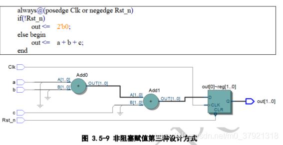
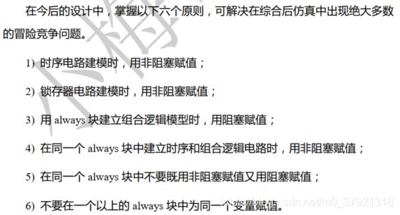
- 3.5 阻塞/非阻塞赋值
- 3.7 按键消抖
- 3.8 加减法计数器
- 3.9 8位7段数码管HEX显示驱动
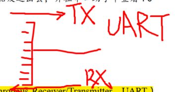
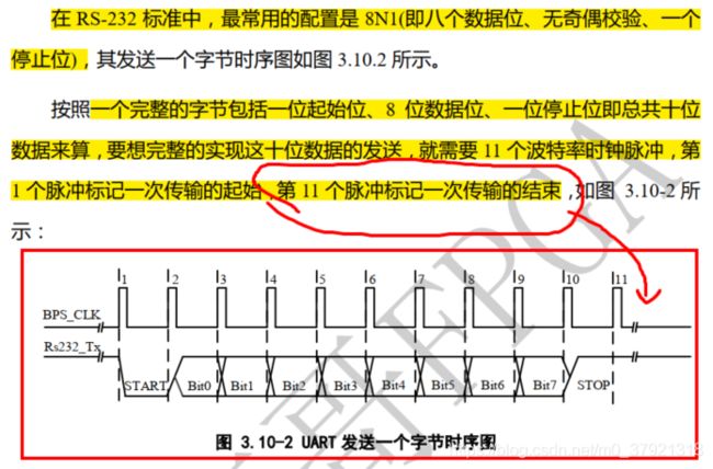
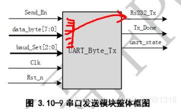
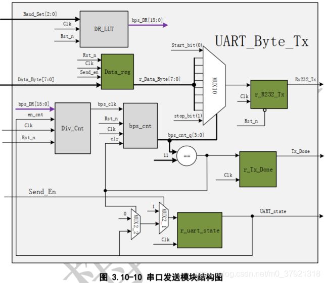
- 3.10.1 串口发送UART_TX
- 3.10.2 串口接收UART_RX
3.4 BCD计数器
/******************************p142 3.4.2 级联BCD码计数器********************************/
module  BCDcnt(clk,rst_n,cin,cout,cnt);

input               clk,rst_n,cin;
output  reg         cout;
output  reg [3:0]   cnt;
wire                end_cnt,add_cnt;

always @(posedge clk or negedge rst_n)begin
    if(!rst_n)  cnt <= 0;
    else if(add_cnt)begin
        if(end_cnt)
            cnt <= 0;
        else
            cnt <= cnt + 1;
    end
end
assign  add_cnt     =       cin == 1'b1;//相当于下一级计数器的使能信号
assign  end_cnt     =       cnt == 4'd9;

always@(posedge clk or negedge rst_n)begin
    if(!rst_n)          			cout    <=  1'b0;
    else if(add_cnt && end_cnt)    	cout    <=  1'b1;//这里cout<=1的条件可以只是end_cnt吗??
    else                			cout    <=  1'b0;
end

endmodule
/******************************p144 3.4 BCDcnt3_top********************************/
`include    BCDcnt.v
module  BCDcnt3_top(cin,clk,rst_n,cout,q);
input               rst_n,clk,cin;
output      [12:0]  q;
wire                cout0,cout1;
wire        [3:0]   cnt0,cnt1,cnt2;

assign  q={cout,cnt2,cnt1,cnt0};

BCDcnt  u0(.clk(clk),.rst_n(rst_n),.cin(cin),  .cout(cout0),.cnt(cnt0));
BCDcnt  u1(.clk(clk),.rst_n(rst_n),.cin(cout0),.cout(cout1),.cnt(cnt1));
BCDcnt  u2(.clk(clk),.rst_n(rst_n),.cin(cout1),.cout(cout), .cnt(cnt2));

endmodule
3.5 阻塞/非阻塞赋值
3.7 按键消抖
之前写的一篇按键消抖的博文
https://blog.csdn.net/m0_37921318/article/details/105890194
复盘了部分代码
/******************************p163 3.17 独立按键消抖模块设计及验证********************************/
module  key_filter(key_in,clk,rst_n,key_flag,key_state);

input               key_in,clk,rst_n;
output  reg         key_state;
output  reg         key_flag;

        reg [19:0]  cnt;

wire                end_cnt,en_cnt;

//20ms计数器
always@(posedge clk or negedge rst_n)begin
    if(!rst_n)  begin
        cnt <=  0;
    end
    else if(en_cnt)begin
        if(end_cnt)
            cnt <=  20'd0;
        else
            cnt <=  cnt+1;
    end
end
//递增使能信号应该是 状态(FILTER0/FILTER1)
assign  end_cnt=    cnt==20'd999_000;

reg key_sync_a,key_sync_b;
//输入信号同步化
always@(posedge clk or negedge rst_n)begin
    if(!rst_n)  begin
        key_sync_a   <=  0;
        key_sync_b   <=  0;
    end
    else    begin
        key_sync_a   <=  key_in;
        key_sync_b   <=  key_sync_a;
    end
end

reg key_edge_a,key_edge_b;
//边沿检测
always@(posedge clk or negedge rst_n)begin
    if(!rst_n)  begin
        key_edge_a   <=  0;
        key_edge_b   <=  0;
    end
    else    begin
        key_edge_a   <=  key_sync_b;
        key_edge_b   <=  key_edge_a;
    end
end
assign  pedge   = key_edge_a & !key_edge_b;
assign  nedge   =!key_edge_a &  key_edge_b;

reg [3:0]   state_c,state_n;
//主状态机UP-FILTER0-DOWN-FILTER1
//状态转移
always@(posedge clk or negedge rst_n)begin
    if(!rst_n)  state_c <=  UP;
    else        state_c <=  state_n;
end

//组合逻辑
always@(*)begin
    case(state_c)
        UP:         state_n =(nedge)?FILTER0:state_n;
        FILTER0:    state_n = end_cnt ? DOWN:(pedge ? UP:state_n);
        DOWN:       state_n =(pedge)?FILTER1:state_n;
        FILTER1:    state_n = end_cnt ? UP:(nedge ? DOWN:state_n);
        default:    state_n = UP;
    endcase
end

//输出时序
reg en_cnt;
always@(posedge clk or negedge rst_n)begin
    if(!rst_n)begin
        en_cnt      <=0;
        key_flag    <=0;
        key_state   <=0;
    end
    else    begin
        case(state_c)
            UP:     begin
                en_cnt<=(nedge)?1:en_cnt;
            end
            FILTER0:begin
                key_flag<=end_cnt ? 1:key_flag;
                key_state<=end_cnt ? 0:key_state;
                en_cnt<=0;
            end
            DOWN:   begin
                en_cnt<=(pedge)?1:en_cnt;
            end
            FILTER1:begin
                key_flag<=end_cnt ? 1:key_flag;
                key_state<=end_cnt ? 1:key_state;
                en_cnt<=0;
            end
            default:begin
                en_cnt      <=0;
                key_flag    <=0;
                key_state   <=0;
            end
        endcase
    end
end
assign  key_state=state_c;

endmodule
3.8 加减法计数器
按下0键+1,按下1键-1
控制模块如下:
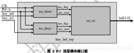
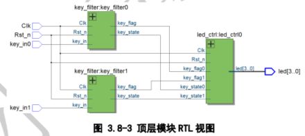
需要注意的是:按键按下的表示是
key_flag && !key_state ==1
即按键有按下/释放动作 && 按键状态为DOWN按下
(key_state==1为弹起来的UP,==0为按下去的DOWN)
因此需要将key_flag和key_state为1的时序进行对齐,如果没对齐需要加触发器使其对齐。
同理,按键释放的表示是
key_flag && key_state ==1
module key_ctrl(key_flag_add,key_flag_minus,key_state_add,key_state_minus,clk,rst_n,num);
input   。。。
output  reg [4:0]   num;

always@(posedge clk or negedge rst_n)begin
    if(!rst_n)
        num<=0;
    else if(key_flag_add && !key_state_add)
        num<=num+1;
    else if(key_flag_minus && !key_state_minus)
        num<=num-1;
    else
        num<=num;
end
3.9 8位7段数码管HEX显示驱动
/******************************p185 3.9 4位7段数码管循环点亮驱动设计********************************/
module  hex4(data,clk,rst_n);
input               clk,rst_n;
input       [15:0]  data;//4个BCD码输入数字
output  reg [3:0]   sel; //4数码管数选信号输出
output  reg [6:0]   seg; //1数码管上的点亮的灯条信号选择输出
        reg [14:0]  cnt;


always @(posedge clk or negedge rst_n)begin
    if(!rst_n)  cnt <= 0;
    else if(add_cnt)begin
        if(end_cnt)
            cnt <= 0;
        else
            cnt <= cnt + 1;
    end
end
assign  add_cnt     =       1;
assign  end_cnt     =       cnt == 15'd24_999;

//1kHz的时钟
reg clk_1k;
always @(posedge clk or negedge rst_n)begin
    if(!rst_n)          clk_1k <= 0;
    else if(end_cnt)    clk_1k=~clk_1k;
    else                clk_1k=clk_1k;
    end
end

always @(posedge clk_1k or negedge rst_n)begin
    if(!rst_n)              sel<=4'b0000;
    else if(sel==4'b1000)   sel<=4'b0001;
    else                    sel<=sel<<1;
end

reg [3:0]   disp_data;
always @(posedge clk_1k or negedge rst_n)begin
    if(!rst_n)  disp_data<=4'b0000;
    else
        case(sel)
            4'b0001:disp_data<=data[3:0];
            4'b0010:disp_data<=data[7:4];
            4'b0100:disp_data<=data[11:8];
            4'b1000:disp_data<=data[15:12];
            default:disp_data<=4'b0000
        endcase
end

reg [3:0]   disp_data;
always @(posedge clk_1k or negedge rst_n)begin
    if(!rst_n)  seg<=7'b;
    else
        case(disp_data)
            4'd1:   seg<=7'b     ;
            4'd2:   seg<=7'b     ;
            4'd3:   seg<=7'b     ;
            4'd4:   seg<=7'b     ;


            4'd9:   seg<=7'b     ;
            default:seg<=7'bz;
        endcase
end

endmodule
3.10.1 串口发送UART_TX
3.10.2 串口接收UART_RX
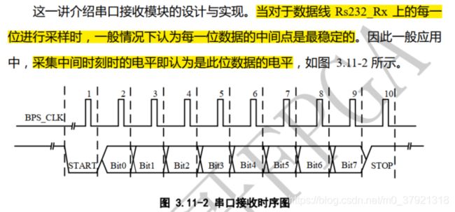
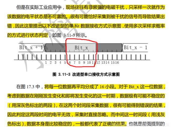
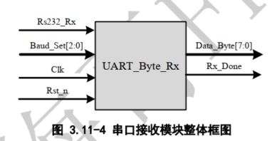
思路:设置波特率时钟,将波特率max计数值除以16,为一个bps_clk,并在检测到下降沿时,开始对bps_clk进行计数 得到bps_cnt,范围在0-159(16*10[START_BIT+8个串行数据bit+STOP_BIT]);则定义寄存器数组深度为8,宽度为3(8个3bit寄存器,最高位标志着该bit的真实值);第一个bit的0-15范围内的6,7,8,9,10,11计数值进行累加放在寄存器1中,间隔16个的累加值放在寄存器2中,以此类推。并在bps_cnt==16’d159时输出这8个3bit寄存器的最高位r_data_byte[x]【2】,(x为0~7),即输出data_byte[7:0] 。

