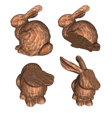
计算机图形学:纹理
第八章:纹理(Texture)
参考:视差遮蔽映射
1 程序贴图(Procedure Texture)
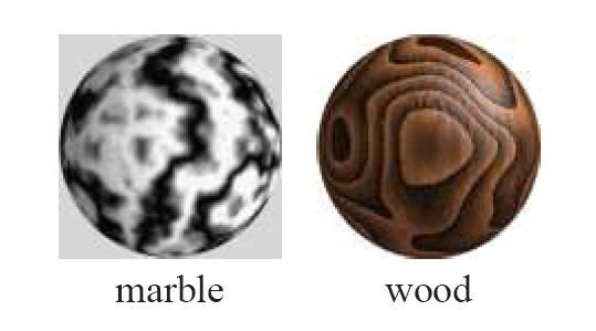
由计算机算法生成的贴图,而非存储的数据,有低存储的优点。主要用于木材,大理石,花岗岩,金属,石头等材质。程序贴图纹理通常用于离线渲染应用程序,而图像纹理在实时渲染中更为常见,毕竟快。
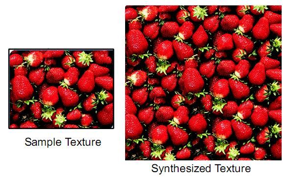
2 纹理合成(Texture Synthesis)
2.1 Pixel-based texture synthesis
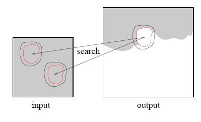
Synthesis a new texture pixel by pixel, where the value of each pixel is determined by the local neighbourhood(e.g. 3x3, 5x5), choosing the input pixel with a similar neighboorhood
2.2 Patch-based texture synthesis
3纹理映射(Texture Mapping)
3.1 By natural parameterization
For regular objects, such as sphere, cube, cylinder
3.2 By manually specify texture coordinates
For complex objects, each vertex is specified a texture coordinate
3.3 Mesh parametrization
Construct a mapping from 3D mesh models to planar domain
3.4 Conformal parametrization and area preserving: inverse curvature map
在网格上从网格边的边长到网格顶点的高斯曲率的映射称之为曲率映射,利用共形几何理论,由网格曲面的曲率映射的切映射,可以证明这个映射是可逆的
4 纹理采样(Texture Filtering)
Aliasing(走样) and Anti-aliasing(反走样)
Generally, aliasing is caused when a signal is sampled at too low frequency rate. So that many high frequency features of the signal are missed.
如下图所示,黑色线为原始信号曲线,红色为采样曲线,结果相差很大,就是采样走样了:
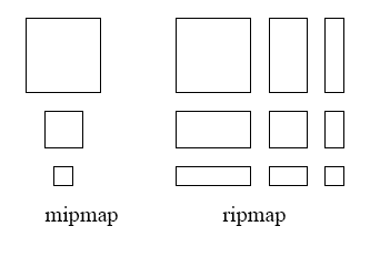
4.1 Mipmapping:Isotropic(各向同性) filtering
4.2 Ripmap:Anisotropic(各向异性) Filtering
5 体纹理(Solid Texture,Volume Texture)
Have a 3-D array of texture values (e.g., a block of marble).Use a function [xyz] -> [RGB] to map colors to points
In practice the map is often defined procedurally, no need to store an entire 3D array of colors, Just define a function to generate a color for each 3D point
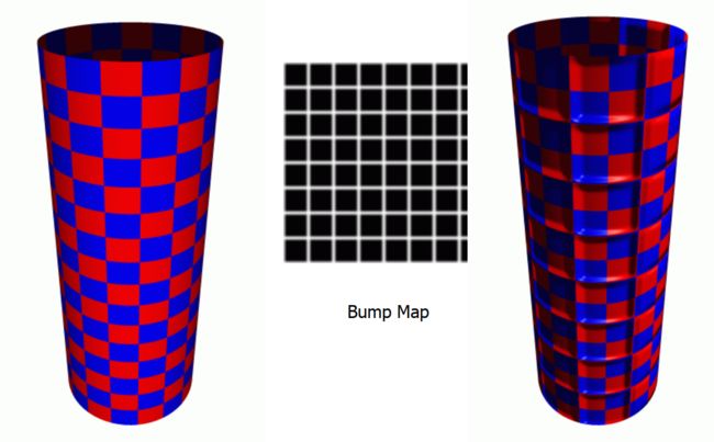
6 凹凸贴图(Bump Mapping)
水波浪,每个待渲染的像素在计算照明之前都要加上一个从高度图中找到的扰动
[外链图片转存失败,源站可能有防盗链机制,建议将图片保存下来直接上传(img-VlvDymjS-1584097934563)(https://upload.wikimedia.org/wikipedia/commons/0/0a/Bump-map-demo-full.png)]
实现算法:
修改点(u,v)的法线:
du = 1/BumpMapWidth
dv = 1/BumpMapHeight
u_gradient = BumpMap(u-du, v) - BumpMap(u+du, v)(U方向的坡度)
v_gradient = BumpMap(u, v-dv) - BumpMap(u, v+dv) (V方向的坡度)
NewNormal = OldNormal + (T * u_gradient) + (B * v_gradient)
- 不能产生侧面轮廓效果(silhouette)
- 不支持自遮挡或者自阴影
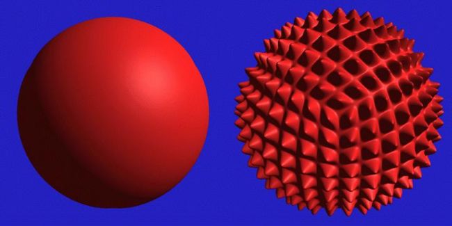
7 移位贴图(Displacement Mapping)
移位贴图的每一个纹素中存储了一个向量,这个向量代表了对应顶点的位移
- Use the texture map to actually move the surface point(沿法向移动)
- The geometry must be displaced before visibility is determined
- Pixel-based processing
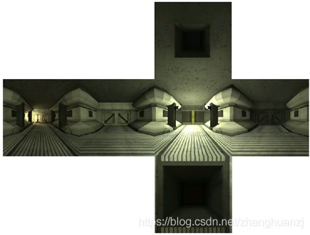
8 立方体贴图(Cube Map)
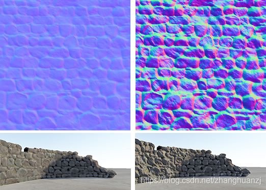
9 法线贴图(Normal Mapping)
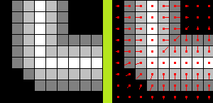
- 直接把Normal存到一张NormalMap里面,从NormalMap里面采回来的值就是Normal
- NormalMap存的Normal是基于切线空间
- 原理和Bump Mapping类似,只不过这里法向量不用计算而是直接读取,弊端也是一样的
- 法线贴图常常用在低解析度模型,伪装出高解析度的模型细节表现。造成了模型表面更多细节的假象。然而,从侧面来看,模型本身并没有改变。
9.1 Tangent Space
Why Use Tangent Space
- 法向量通常用来计算光照,如果法向量定义在世界坐标系中,那么光线,视线方向都不用作任何变换就还可以直接与法向量进行计算。但是一旦物体运动,那么法线贴图中所有的法向量均需要进行相应的变换才可以。而法线贴图的计算通常是在像素着色器中进行的,成千上万的物体,这带来的计算量是十分巨大的,而旋转light/camera/vertex这些是可以接受的。并且物体还不能进行非刚体运动;
- 对于不同的物体,不能够复用同样的法线贴图,譬如一个正方体的6个面,因为朝向不同,不能共享一张这样的法线贴图;
9.2 Create Normal Map
TangentU(i,j) = (1, 0, (HeightMap(i+1,j) - HeightMap(i-1,j))*a);
TangentV(i,j) = (0, 1, (HeightMap(i,j+1) - HeightMap(i,j-1))*a);

Normal = normalize(cross(TangentU, TangentV));
Normal = (Normal + (1, 1, 1)) / 2; //To Tangent Space
9.3 Gram-Schmidt
给定n个线性无关向量组成的集合 S = e 1 , e 2 , . . . e n S={e_1,e_2,...e_n} S=e1,e2,...en,该算法可以计算出集合 S ′ = e 1 ′ , e 2 ′ , . . . e n ′ S'={e_1',e_2',...e_n'} S′=e1′,e2′,...en′,当i不等于j时 e i ′ ⋅ e j ′ = 0 e_i'\cdot e_j'=0 ei′⋅ej′=0
- 令 e 1 ′ = e 1 e_1' = e_1 e1′=e1
- i=2
- 从向量 e i e_i ei中减去 e i e_i ei在向量 e 1 ′ , e 2 ′ , . . . e i 1 ′ e_1',e_2',...e_{i_1}' e1′,e2′,...ei1′上的投影,结果保存到 e i ′ e_i' ei′中,即
e i ′ = e i − ∑ k = 1 i − 1 e i ⋅ e k ′ e k ′ 2 e k ′ e_i' = e_i - \sum_{k=1}^{i-1}\frac{e_i\cdot e_k'}{e_k'^2}e_k' ei′=ei−k=1∑i−1ek′2ei⋅ek′ek′ - 如果i
9.4 切向量的计算
可以将三角形的法向量作为切线空间的法向量,这样在大部分情况下norma的方向就是三角形面的法向量,也就是在切空间的Z轴(0,0,1)因为向量每个维度的取值范围是[-1,1],而纹理每个通道的取值范围为[0,1],所以要做一步映射,即 pixel =(normal + 1)/2,(0,0,1)就变成了(0.5,0.5,1),而这个颜色就是法线贴图中大片的蓝色
要计算顶点的切线空间向量(B-bitangent,T-tangent,N-normal),首先要计算每个三角面的切线空间向量,假设三角形的三个顶点为 P 0 , P 1 , P 2 P_0,P_1,P_2 P0,P1,P2,纹理坐标为 ( u 0 , v 0 ) , ( u 1 , v 1 ) , ( u 2 , v 2 ) (u_0, v_0),(u_1, v_1),(u_2, v_2) (u0,v0),(u1,v1),(u2,v2)
Q 1 = P 1 − P 0 Q 2 = P 2 − P 0 ( t 1 , b 1 ) = ( u 1 − u 0 , v 1 − v 0 ) ( t 2 , b 2 ) = ( u 2 − u 0 , v 2 − v 0 ) Q 1 = t 1 ∗ T + b 1 ∗ B Q 2 = t 2 ∗ T + b 2 ∗ B [ Q 1 ⋅ x Q 1 ⋅ y Q 1 ⋅ z Q 2 ⋅ x Q 2 ⋅ x Q 2 ⋅ x ] = [ t 1 b 1 t 2 b 2 ] [ T x T y T z B x B y B z ] [ T x T y T z B x B y B z ] = 1 t 1 b 2 − t 2 b 1 [ b 2 − b 1 − t 2 t 1 ] [ Q 1 ⋅ x Q 1 ⋅ y Q 1 ⋅ z Q 2 ⋅ x Q 2 ⋅ x Q 2 ⋅ x ] Q_1 = P_1 - P_0\\ \ \\ Q_2 = P_2 - P_0\\ \ \\ (t_1, b_1) = (u_1 - u_0, v_1 - v_0)\\ \ \\ (t_2, b_2) = (u_2 - u_0, v_2 - v_0)\\ \ \\ Q_1 = t_1*T + b_1*B\\ \ \\ Q_2 = t_2*T + b_2*B\\ \ \\ \begin{bmatrix} Q_{1\cdot}x & Q_{1\cdot}y & Q_{1\cdot}z\\ Q_{2\cdot}x & Q_{2\cdot}x & Q_{2\cdot}x \end{bmatrix} = \begin{bmatrix} t_1 & b_1 \\ t_2 & b_2 \end{bmatrix} \begin{bmatrix} T_x & T_y & T_z \\ B_x & B_y & B_z \end{bmatrix} \ \\ \ \\ \begin{bmatrix} T_x & T_y & T_z \\ B_x & B_y & B_z \end{bmatrix} = \frac{1}{t_1b_2-t_2b_1} \begin{bmatrix} b_2 & -b_1 \\ -t_2 & t_1 \end{bmatrix} \begin{bmatrix} Q_{1\cdot}x & Q_{1\cdot}y & Q_{1\cdot}z\\ Q_{2\cdot}x & Q_{2\cdot}x & Q_{2\cdot}x \end{bmatrix} Q1=P1−P0 Q2=P2−P0 (t1,b1)=(u1−u0,v1−v0) (t2,b2)=(u2−u0,v2−v0) Q1=t1∗T+b1∗B Q2=t2∗T+b2∗B [Q1⋅xQ2⋅xQ1⋅yQ2⋅xQ1⋅zQ2⋅x]=[t1t2b1b2][TxBxTyByTzBz] [TxBxTyByTzBz]=t1b2−t2b11[b2−t2−b1t1][Q1⋅xQ2⋅xQ1⋅yQ2⋅xQ1⋅zQ2⋅x]
这样便求解得到了三角形的切向量。顶点的切向量为相邻三角形切向量的平均值。此时的切向量不一定垂直,需要Gram-Schmidt算法正交化,并且规范化,最终计算得到的切线空间转化矩阵如下所示:
[ T x T y T z B x B y B z N x N y N z ] \begin{bmatrix} T_x & T_y & T_z \\ B_x & B_y & B_z \\ N_x & N_y & N_z \end{bmatrix} ⎣⎡TxBxNxTyByNyTzBzNz⎦⎤
9.5 法线贴图的使用
映射分为两部分,一部分为顶点的计算,一部分为像素的计算。
- 对顶点的计算包括求出指向相机的向量V和指向光源的向量L,以及将其转换到切线空间的计算(vertex shader);
- 三角形表面的V和L通过插值获得,结合采样得到的N进行颜色的计算(fragment shader)
10 视差贴图(Parallax Mapping)
- 平面上看到点A就用A对应的贴图采样,但在有高低起伏的表面,点A可能被B遮挡,视差贴图就是找到对应于A的点B进行采样
- 这里粗糙的红线代表高度贴图中的数值的立体表达,向量V代表观察方向。如果平面进行实际位移,观察者会在点B看到表面。然而我们的平面没有实际上进行位移,观察方向将在点A与平面接触。视差贴图的目的是,在A位置上的fragment不再使用点A的纹理坐标而是使用点B的。随后我们用点B的纹理坐标采样,观察者就像看到了点B一样。
- 法线贴图会看到所有的点,所以效果没有那么逼真
这里P向量的长度与A点处的高度相关,除以z是将xy做一个映射;平面的边缘上,纹理坐标超出了0到1的范围进行采样,根据纹理的环绕方式导致了不真实的结果。解决的方法是当它超出默认纹理坐标范围进行采样的时候就丢弃这个fragment:
vec2 parallaxMapping(in vec3 V, in vec2 T, out float parallaxHeight)
{
   // get depth for this fragment
   float initialHeight = texture(u_heightTexture, o_texcoords).r;

   // calculate amount of offset for Parallax Mapping
   vec2 texCoordOffset = parallaxScale * V.xy / V.z * initialHeight;

   // calculate amount of offset for Parallax Mapping With Offset Limiting
   // 带偏移上限的视差映射可以避免在摄像机向量V和法向量N夹角太大时的一些诡异的结果。
   // texCoordOffset = parallaxScale * V.xy * initialHeight;

   // retunr modified texture coordinates
   return o_texcoords - texCoordOffset;
}
11 陡峭视差映射(Steep Parallax Mapping)
陡峭视差映射,不像简单的视差映射近似,并不只是简单粗暴的对纹理坐标进行偏移而不检查合理性和关联性,会检查结果是否接近于正确值。
算法:
我们从上到下遍历深度层,我们把每个深度层和储存在深度贴图中的它的深度值进行对比。如果这个层的深度值小于深度贴图的值,就意味着这一层采样到的深度大于层的深度。我们继续这个处理过程直到有一层的深度高于储存在深度贴图中的值
vec2 steepPallaxMapping(in vec3 v, in vec2 t)
{
	// determine number of layers from angle between V and N
	// 当垂直看一个表面的时候纹理时位移比以一定角度看时的小。我们可以在垂直看时使用更少的样本,以一定角度看时增加样本数量:
	const float minLayers = 5;
	const float maxLayers = 15;
	float numLayers = mix(maxLayers, minLayers, abs(dot(vec3(0, 0, 1), v)));

	// height of each layer
	float layerHeight = 1.0 / numLayers;
	// depth of current layer
	float currentLayerHeight = 0;
	// shift of texture coordinates for each iteration
	vec2 dtex = gHeightScale * v.xy / v.z / numLayers;

 	// current texture coordinates
	vec2 currentTextureCoords = t;

	// get first depth from heightmap
 	float heightFromTexture = texture(NormTexSampler, currentTextureCoords).a;

	// while point is above surface
	while(heightFromTexture > currentLayerHeight)
	{
		// to the next layer
		currentLayerHeight += layerHeight;
		// shift texture coordinates along vector V
		currentTextureCoords -= dtex;
		// get new depth from heightmap
		heightFromTexture = texture(NormTexSampler, currentTextureCoords).a;
   }

   return currentTextureCoords;
}
12 视差遮蔽映射(Parallax Occlusion Mapping)
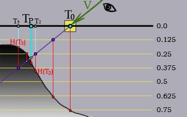
视差遮蔽映射(POM)是陡峭视差映射的另一个改进版本。浮雕视差映射用了二分搜索法来提升结果精度,但是搜索降低程序性能。视差遮蔽映射旨在比浮雕视差映射更好的性能下得到比陡峭视差映射更好的效果。但是POM的效果要比浮雕视差映射差一些。视差遮蔽映射简单的对陡峭视差映射的结果进行插值。
nextHeight = H(T3) - currentLayerHeight  //Left triangle line length, 负
prevHeight = H(T2) - (currentLayerHeight - layerHeight) //Right triangle line length, 正
weight = nextHeight / (nextHeight - prevHeight) // 占总的比例
Tp = T(T2) weight + T(T3) (1.0 - weight)
13 浮雕视差映射(Relief Parallax Mapping)
浮雕视差映射升级了陡峭视差映射,让我们的shader能找到更精确的纹理坐标。首先你先用陡峭视差映射,然后你能得到交点前后的两个层,和对应的深度值。在下面的图中这两个层分别对应纹理坐标T2和T3。现在你可以用二分法来进一步改进你的结果,每一次搜索迭代可以使精确度提升一倍。
// Start of Relief Parallax Mapping

// decrease shift and height of layer by half
vec2 deltaTexCoord = dtex / 2;
float deltaHeight = layerHeight / 2;

// return to the mid point of previous layer
currentTextureCoords += deltaTexCoord;
currentLayerHeight -= deltaHeight;

// binary search to increase precision of Steep Paralax Mapping
const int numSearches = 5;
for(int i=0; i<numSearches; i++)
{
  // decrease shift and height of layer by half
  deltaTexCoord /= 2;
  deltaHeight /= 2;

  // new depth from heightmap
  heightFromTexture = texture(u_heightTexture, currentTextureCoords).r;

  // shift along or agains vector V
  if(heightFromTexture > currentLayerHeight) // below the surface
  {
     currentTextureCoords -= deltaTexCoord;
     currentLayerHeight += deltaHeight;
  }
  else // above the surface
  {
     currentTextureCoords += deltaTexCoord;
     currentLayerHeight -= deltaHeight;
  }
}

// return results
parallaxHeight = currentLayerHeight;
return currentTextureCoords;
