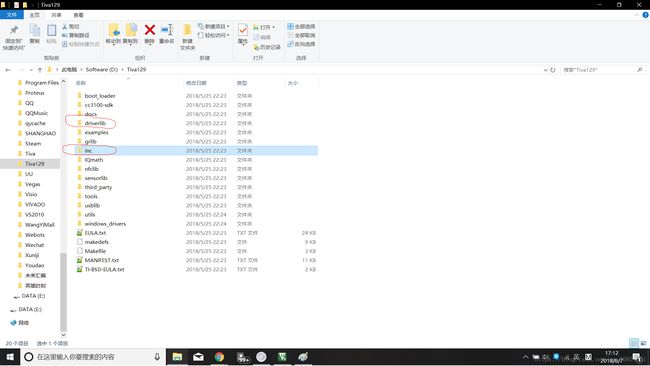
\keil_v5 keil可执行文件目录
\TivaWare_C_Series-2.1.4.178 TIVA系列驱动及样例
WIN7及以上操作系统,2G内存
TM4129XL开发板
Micro-USB数据线一根
1.打开keil5,Project→New uVisonProject,新建一个项目 ,选择好目录后,选择芯片如下图
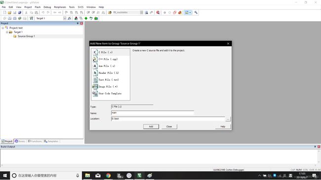
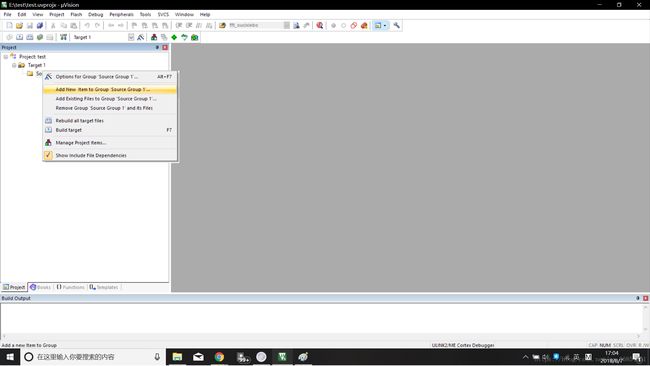
2.单击Source Group 1右键,选择Add New Item to Group “Source Group 1 “如下图所示,生成一个源文件main.c,并完成一个最简单的主函数
3.接下来完成一个LED灯闪烁的工程
(1).首先把固件库文件添加到项目中:
点击Target1右键,Add Group
点击New Group右键,Add Existing File to Group “New Group”,将driverlib.lib库文件添加到此组中,如下图所示,注意文件类型为为LIB
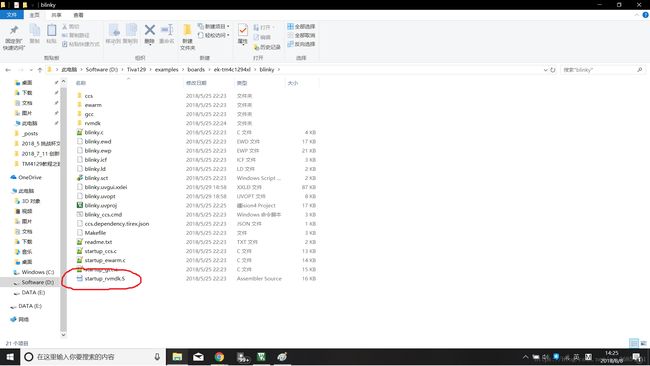
(2).添加开始文件Startup_Tm4c129.s,在下载的例程工程中进行拷贝
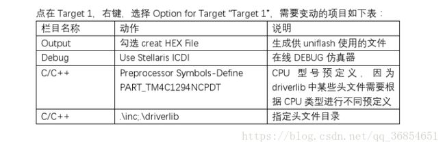
(3).配置工程
(4).将之前添加的C文件改为如下代码
#include
#include
#include "inc/hw_memmap.h"
#include "driverlib/debug.h"
#include "driverlib/gpio.h"
#include "driverlib/sysctl.h"
//*****************************************************************************
//
//! \addtogroup example_list
//! <h1>Blinky (blinky)h1>
//!
//! A very simple example that blinks the on-board LED using direct register
//! access.
//
//*****************************************************************************
//*****************************************************************************
//
// The error routine that is called if the driver library encounters an error.
//
//*****************************************************************************
#ifdef DEBUG
void
__error__(char *pcFilename, uint32_t ui32Line)
{
while(1);
}
#endif
//*****************************************************************************
//
// Blink the on-board LED.
//
//*****************************************************************************
int
main(void)
{
volatile uint32_t ui32Loop;
//
// Enable the GPIO port that is used for the on-board LED.
//
SysCtlPeripheralEnable(SYSCTL_PERIPH_GPION);
//
// Check if the peripheral access is enabled.
//
while(!SysCtlPeripheralReady(SYSCTL_PERIPH_GPION))
{
}
//
// Enable the GPIO pin for the LED (PN0). Set the direction as output, and
// enable the GPIO pin for digital function.
//
GPIOPinTypeGPIOOutput(GPIO_PORTN_BASE, GPIO_PIN_0);
//
// Loop forever.
//
while(1)
{
//
// Turn on the LED.
//
GPIOPinWrite(GPIO_PORTN_BASE, GPIO_PIN_0, GPIO_PIN_0);
//
// Delay for a bit.
//
for(ui32Loop = 0; ui32Loop < 200000; ui32Loop++)
{
}
//
// Turn off the LED.
//
GPIOPinWrite(GPIO_PORTN_BASE, GPIO_PIN_0, 0x0);
//
// Delay for a bit.
//
for(ui32Loop = 0; ui32Loop < 200000; ui32Loop++)
{
}
}
}
(5).最后选择编译并且下载程序,按开发板上的Reset键便可以看到灯闪烁现象。