FPGA工程师笔试面试题(四)
Verilog编程练习:
1、根据描述功能用verilog编写一段代码并用状态机来实现该功能
(1)状态机:实现一个测试过程,该过程包括启动准备状态、启动测试、停止测试、查询测试结果、显示测试结果、测试结束返回初始化6个状态;用时间来控制该过程,90秒内完成该过程;
(2)描述状态跳转时间
(3)编码实现
解答过程如下:
(1)状态机:

S0表示初始化状态(initial)
S1表示准备状态:准备20秒钟。
S2 表示测试启动状态(start):经过30秒测试完成。
S3表示测试停止状态(stop):表示测试结束。
S4表示测试查询状态:进行测试结果查询。
S5表示显示查询结果状态(display):显示测试结果。
(2)
C0表示timer = 1秒时跳到S1状态。
C1表示timer =41 秒时,进入S2状态。
C2 表示timer= 71秒,进入S3状态。
C3 表示timer = 72秒,进入S4状态。
C4 表示timer =73秒时,进入S5结果显示状态。
C5 表示timer = 74 秒,返回S0初始化状态。
(3)
reg[5:0] state;
wire[63:0] timer;

always @(posedge clk)
	begin
		if(reset)
			state S0;
		else
			begin
				case(state)
					S0 ://inital
						begin
							if(timer == 1)
								state = state;
							else
								state = S0;
						end
					S1 :// ready
						begin
							if(timer == 41)
								state = S2;
							else
								state = state;
						end
					S2 ://start
						begin
							if(timer == 71)
								state = S3;
							else
								state = state;
						end
					S3 ://stop
						begin
							if(timer == 72)
								state = S4;
							else
								state = state;
						end
					S4 ://search
						begin
							if(timer == 73)
								state = S5;
							else
								state = state;
						end
					S5 ://display
						begin
							if(timer == 74)
								state = S0;
							else
								state = state;
						end
					default : state = S0;
				end case
			end
	end
2、写同步、异步复位及置位D触发器的verilog module。(扬智电子笔试)
//带有异步清0、异步置1的D触发器模块描述

module D_trigger(clk,set_n,rst_n,D,Q);
	input clk;
	input set_n;
	input rst_n;
	input D;
	output Q;

	reg Q;

	always @(posedge clk or negedge rst_n or negedge set_n)
	begin
		if(!rst_n)//异步清0 低有效
			Q <= 1'b0;
		else if(~set_n)
			Q <= 1'b1;
		else
			Q <= D;
	end
endmodule
//同步复位、置位D触发器
module D_trigger(clk,set_n,rst_n,D,Q);
	input clk;
	input set_n;
	input rst_n;
	input D;
	output Q;

	reg Q;

	always @(posedge clk)
	begin
		if(!rst_n)//同步清0 低有效
			Q <= 1'b0;
		else if(!set_n)
			Q <= 1'b1;
		else
			Q <= D;
	end
endmodule
2、描述8位D触发器逻辑
module dff8(clk , reset, d, q);
input        clk;
input        reset;
input  [7:0] d;
output [7:0] q;
reg   [7:0] q;
always @ (posedge clk or posedge reset)
   if(reset)
     q <= 0;
   else
     q <= d;
endmodule
3、请用HDL描述四位的全加法器。(仕兰微电子)
4位全加器:能实现4位二进制数全加的数字电路模块,称之为四位全加器(逐位进位 超前进位)多位全加器连接可以是逐位进位,也可以是超前进位。逐位进位也称串行进位,其逻辑电路简单,但速度也较低。
①第一种方法:仿真源文件代码:(行为描述和结构描述基本上差不多)
//	①第一种方法:仿真源文件代码:(行为描述和结构描述基本上差不多)
//数据流描述4位全加器
    module add_4
    (
    	input[3:0] a,b,
    	input cin
    	output[3:0] sum,
    	output cout,
    );
    assign{cout,sum} = a+b+cin;
    endmodule

//测试文件
//在写testbeach文件之前,先普及一点testbeach的知识:
//一般来讲,在数据类型声明时,和被测模块的输入端口相连的信号定义为reg类型,这样便于在initial语句和always语句块中对其进行赋值;
//和被测模块输出端口相连的信号定义为wire类型,便于进行检测。Testbench模块最重要的的任务就是利用各种合法的语句,产生适当的时序和数据,以完成测试,并达到覆盖率要求。
//测试文件源代码:
module adder_4();
    wire[3:0] sum;
    wire cout;
    reg[3:0] a,b;
    reg cin;
    initial
        begin//这个其实就是真值表的应用
            #0 a = 4'b0001; b = 4'b1010; cin = 1'b0;
            #5 a = 4'b0010; b = 4'b1010; cin = 1'b1;
            #5 a = 4'b0010; b = 4'b1110; cin = 1'b0;
            #5 a = 4'b0011; b = 4'b1100; cin = 1'b1;
            #5 a = 4'b0111; b = 4'b1001; cin = 1'b0;
            #5 a = 4'b0001; b = 4'b1100; cin = 1'b1;
            #5 a = 4'b0011; b = 4'b1100; cin = 1'b0;
            #5 a = 4'b0111; b = 4'b1111; cin = 1'b1;
            #5 $finish;
        end
    add_4 u1(.a(a),.b(b),.cin(cin),.sum(sum),.cout(cout));
endmodule
//在这里主要用到的是Verilog的拼接运算符——{信号1,信号2}, 其中信号1是高位置,信号2是低位值
module add4
(
		input[3:0] a,b,
		output[3:0] sum,
		output cout
);
assign {cout,sum} = a + b;
endmodule

//测试文件
module adder4();
reg [3:0] a,b;
wire  [3:0] sum;
wire cout;
initial
	begin
		a = 0;	b = 0;	#50;
		a = 0;	b = 1;	#50;
		a = 0;	b = 3;	#50;
		a = 0;	b = 7;	#50;
		a = 0;	b = 15;	#50;
		a = 1;	b = 15;	#50;
		a = 3;	b = 15;	#50;
		a = 7;	b = 15;	#50;
		a = 15;	b = 15;	#50;

	end
add4 u2(.a(a),.b(b),.sum(sum),.cout(cout));
endmodule
4、用VERILOG或VHDL写一段代码,实现10进制计数器
//4位10进制计算器
`timescale 1ns/10ps
module counter10(clk,rst,count);
input clk,rst;
output [3:0] count;
reg [3:0] q;
assign count = q;
always@(posedge clk)
begin
  if(!rst)
    q <= 0;
  else if(q >= 4'd9)
    q <= 0;
  else
    q <= q + 1;
end
endmodule


//testbench
module counter10_tb();

reg rst;
reg clk;
wire [3:0] count;

counter10 wt(.clk(clk),.rst(rst), .count(count));

initial
begin
  rst <= 1;
  clk <= 0;
  #50 rst <= 0;
  #1000 rst <= 1;
  #2000 rst <= 0;
end
always
  #10 clk = ~clk;
endmodule
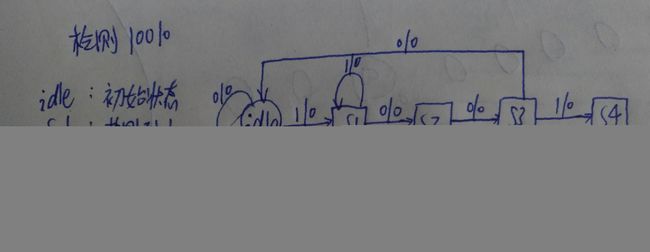
5、画出可以检测10010串的状态图,并verilog实现之。(威盛)
方法1: 状态机如下,修改状态机可实现其他序列检测。
Verilog实现之:
//序列检测
module sequential_detector(clk, rst_n, d, y);
	//输入输出端口定义
	input clk, rst_n, d;
	output y;

	//内部寄存器及连线定义
	reg [2 : 0] curr_state, next_state;

	//状态编码
	parameter idle = 3'b000, s1 = 3'b001, s2 = 3'b010, s3 = 3'b011, s4 = 3'b100;

	//状态机实现
	always@(posedge clk or posedge rst_n)
	begin
		if(!rst_n)
			curr_state <= idle;
		else
			curr_state <= next_state;
	end

	always@(curr_state or d)
		begin
			case(curr_state)
				idle: begin
						if(d == 1) next_state <= s1;
						else next_state <= idle;
					  end
				s1: begin
						if(d == 0) next_state <= s2;
						else next_state <= s1;
					end
				s2: begin
						if(d == 0) next_state <= s3;
						else next_state <= s1;
					end
				s3: begin
						if(d == 1) next_state <= s4;
						else next_state <= idle;
					end
				s4:	begin
						if(d == 0)
						begin
							next_state <= idle;
							y <= 1'b1;
						end
						else next_state <= s1;
					end
				default: next_state <= idle;
			endcase
		end
	end
endmodule
方法2:用移位寄存器实现
//一位寄存器实现特定序列检测 10010
module sequential_detector_shift
(
	input clk;
	input rst_n;
	input din,
	output dout
);

reg dout;
reg [4:0] data;

always @(posedge clk or negedge rst_n)
begin
	if(!rst_n)
		data <= 0;
	else
		data <= {data[3:0],din};
end
assign dout = (data[4:0] == 5'b10010)?  1'b1 : 1'b0 ; //此时输入数据din表示上一时钟的输入
endmodule
参考:
(1)https://blog.csdn.net/qq_37363005/article/details/97890745
(2)https://blog.csdn.net/whm0077/article/details/6141886
(3)https://blog.csdn.net/shanekong/article/details/29638699