HDLBits刷题合集—7 Basic Gates
HDLBits刷题合集—7 Basic Gates
HDLBits-44 Exams/m2014 q4h
Problem Statement
实现以下电路:
![]()
代码如下:
module top_module (
    input in,
    output out);

	assign out = in;

endmodule
HDLBits-45 Exams/m2014 q4i
Problem Statement
实现以下电路:

代码如下:
module top_module (
    output out);

	assign out = 1'b0;

endmodule
HDLBits-46 Exams/m2014 q4e
Problem Statement
实现以下电路:

代码如下:
module top_module (
    input in1,
    input in2,
    output out);

    assign out = ~(in1 | in2);

endmodule
HDLBits-47 Exams/m2014 q4f
Problem Statement
实现以下电路:

代码如下:
module top_module (
    input in1,
    input in2,
    output out);

    assign out = in1 & (~in2);

endmodule
HDLBits-48 Exams/m2014 q4g
Problem Statement
实现以下电路:

代码如下:
module top_module (
    input in1,
    input in2,
    input in3,
    output out);
	wire out1;

    assign out1 = in1 ~^ in2;
    assign out  = in3 ^ out1;

endmodule
HDLBits-49 Gates
Problem Statement
让我们尝试同时构建几个逻辑门。用a和b两个输入建立一个组合电路,
它有7个输出,每个输出都有一个逻辑门驱动:
| output | input |
|---|---|
| out_and | a and b |
| out_or | a or b |
| out_xor | a xor b |
| out_nand | a nand b |
| out_nor | a nor b |
| out_xnor | a xnor b |
| out_anotb | a and-not b |
代码如下:
module top_module(
    input a, b,
    output out_and,
    output out_or,
    output out_xor,
    output out_nand,
    output out_nor,
    output out_xnor,
    output out_anotb
);

	assign out_and   = a & b;
    assign out_or    = a | b;
    assign out_xor   = a ^ b;
    assign out_nand  = ~(a & b);
    assign out_nor   = ~(a | b);
    assign out_xnor  = a ~^ b;
    assign out_anotb = a & (~b);

endmodule
HDLBits-50 7420
Problem Statement
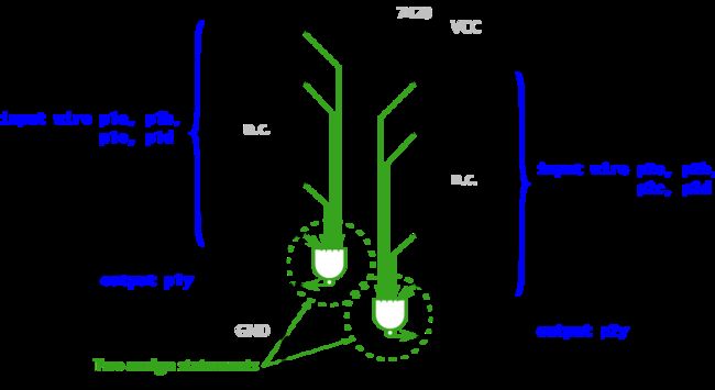
7400系列集成电路是一系列数字芯片,每个芯片有几个逻辑门。7420是一个有两个4输入与非门的芯片。创建一个具有与7420芯片相同功能的模块。它有8个输入和2个输出。
module top_module (
    input p1a, p1b, p1c, p1d,
    output p1y,
    input p2a, p2b, p2c, p2d,
    output p2y );

    assign p1y = ~(p1a & p1b & p1c & p1d);
    assign p2y = ~(p2a & p2b & p2c & p2d);

endmodule
HDLBits-51 Truthtable1
Problem Statement
在前面的练习中,我们使用了简单的逻辑门和几个逻辑门的组合。这些电路都是组合电路。组合意味着电路的输出仅是其输入的函数(在数学意义上)。这意味着对于任何给定的输入值,只有一个可能的输出值。因此,描述组合函数行为的一种方法是显式地列出输入的每个可能值的输出。这就是真值表。
对于N个输入的布尔函数,有2的N次方种可能的输入组合。真值表的每一行列出一个输入组合,因此总有2的N次方行。output列显示的是每个输入值的输出。
| Row number | x3 x2 x1 | y |
|---|---|---|
| 0 | 0 0 0 | 0 |
| 1 | 0 0 1 | 0 |
| 2 | 0 1 0 | 1 |
| 3 | 0 1 1 | 1 |
| 4 | 1 0 0 | 0 |
| 5 | 1 0 1 | 1 |
| 6 | 1 1 0 | 0 |
| 7 | 1 1 1 | 1 |
上面的真值表是一个有三输入一个输出的函数。它有8行,对应8种可能的输入组合,以及一个输出列。有四种输入组合的输出为1,还有四种输入组合的输出为0。
用真值表组成电路
假设我们想要构建上面的电路,但是我们只能使用一组标准的逻辑门。如何构建任意的逻辑函数(表示成真值表)?
创建实现真值表函数电路的一个简单方法是用积之和的形式表示函数。积(表示与)之和s(表示或)表示在真值表的每一行使用一个N输入的与门(用于检测输入匹配是否每一行),然后用一个或门,它只选择那些结果输出“1”的行。
对于上面的例子,如果输入匹配第2行、第3行、第5行或第7行(这是一个4输入或门),则输出为’1’。如果x3=0且x2=1且x1=0(这是一个3输入与gate),则输入与第2行匹配。因此,这个真值表通过使用4输入与门相或简洁地实现。
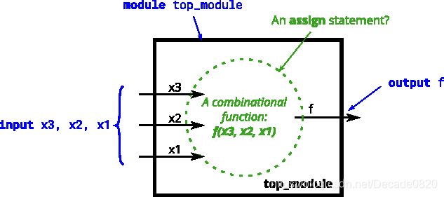
创建一个实现上述真值表的组合电路。
module top_module(
    input x3,
    input x2,
    input x1,  // three inputs
    output f   // one output
);
    assign f = (~x3 & x2) | (x3 & x1);
    //assign f = (~x3 & x2 & ~x1) | (~x3 & x2 & x1) | (x3 & ~x2 & x1) | (x3 & x2 & x1) ;
endmodule
HDLBits-52 Mt2015 eq2
Problem Statement
实现一个这样的电路:有两个2位输入a[1:0]和B[1:0],并产生一个输出z。如果A= B,z的值是1,否则z的值是0。
代码如下:
module top_module ( input [1:0] A, input [1:0] B, output z );
    always @(*)
        begin
   			 if(A == B)
       			  z = 1;
   			 else z = 0;
        end
     //assign z = (A[1:0]==B[1:0]);
endmodule
HDLBits-53 Mt2015 q4a
Problem Statement
模块A需要实现函数z = (x^y) & x,实现这个模块。
代码如下:
module top_module (input x, input y, output z);

    assign z = (x ^ y) & x;

endmodule
HDLBits-54 Mt2015 q4b
Problem Statement
电路B(紧接着上一题的A)可以用以下仿真波形来描述:
| x | y | z |
|---|---|---|
| 0 | 0 | 1 |
| 0 | 1 | 0 |
| 1 | 0 | 0 |
| 1 | 1 | 1 |
代码如下:
module top_module ( input x, input y, output z );

    assign z = x ~^ y;
    //assign z = (~x & ~y) | (x & y);
endmodule
HDLBits-55 Mt2015 q4
Problem Statement
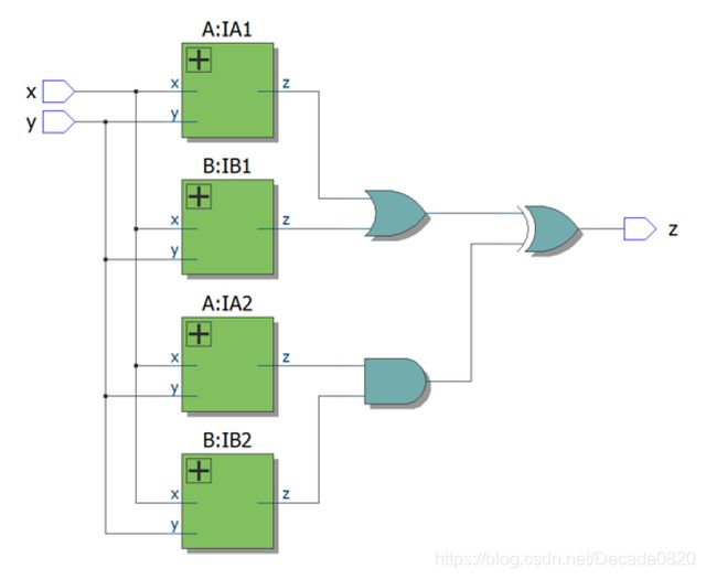
顶层设计由每个子电路A(HDLBits-52 Mt2015 eq2)和B(HDLBits-53 Mt2015 q4a)的两次实例组成,如下所示。
module top_module(
	input x,
	input y,
	output z);

	wire z1, z2, z3, z4;

	A ia1 (x, y, z1);
	B ib1 (x, y, z2);
	A ia2 (x, y, z3);
	B ib2 (x, y, z4);

	assign z = (z1 | z2) ^ (z3 & z4);

endmodule

module A (
	input x,
	input y,
	output z);

	assign z = (x ^ y) & x;

endmodule

module B (
	input x,
	input y,
	output z);

	assign z = ~(x ^ y);

endmodule
HDLBits-56 Ringer
Problem Statement
假设你正在设计一个控制手机铃声和振动马达的电路。每当电话打来时,你的电路必须打开铃声(输出ringer = 1)或震动马达(输出motor= 1),但不能两者都打开。如果手机处于振动模式(输入vibrate_mode = 1),打开马达,否则打开铃声。
尝试只使用assign语句,看看是否可以将问题描述转换为逻辑门的集合。
在设计电路的时候,我们经常要考虑“向后”的问题,从输出开始,然后向后处理输入。这通常与考虑(顺序的、命令式的)编程问题的方法相反,在这种方法中,首先查看输入,然后决定操作(或输出)。对于顺序程序,人们通常会认为“If (inputs are ___ ) then (output should be ___ )”。另一方面,硬件设计人员经常认为“The (output should be ___ ) when (inputs are ___ )”。
上面的问题描述是用适合于软件编程的命令式形式编写(如果ring然后做),因此必须将其转换为更适合于硬件实现的声明式形式(assign ringer =___ )。能够在两种风格之间进行思考和转换是硬件设计人员所需要的最重要的技能之一。
module top_module (
    input ring,
    input vibrate_mode,
    output ringer,       // Make sound
    output motor         // Vibrate
);

	assign motor  = ring & vibrate_mode;
    assign ringer = ring & (~vibrate_mode);

endmodule
HDLBits-57 Thermostat
Problem Statement
采暖/制冷恒温器控制加热器(冬季)和空调(夏季)。实现一个电路,将适时打开和关闭加热器,空调和鼓风机。
恒温器有两种模式:加热模式(模式1)和冷却模式(模式0)。在加热模式下,当过冷时(too_cold = 1),打开加热器,但不要使用空调。在冷却模式下,太冷时打开空调(too_hot = 1),但不要打开加热器。当加热器或空调打开时,打开风扇使空气流通。此外,用户还可以要求打开风扇(fan_on = 1),即使加热器和空调已经关闭。
尝试只使用assign语句,看看是否可以将问题描述转换为逻辑门的集合。
代码如下:
module top_module (
    input too_cold,
    input too_hot,
    input mode,
    input fan_on,
    output heater,
    output aircon,
    output fan);

    // Heater is on when it's too cold and mode is "heating".
    assign heater = mode  & too_cold;
    // Aircon is on when it's too hot and mode is not "heating".
	assign aircon = ~mode & too_hot;
	// Fan should be on when either heater or aircon is on, and also when requested to do so (fan_on = 1).
	assign fan    = (mode & too_cold) | (~mode & too_hot) | fan_on;

endmodule
HDLBits-58 Popcount3
Problem Statement
“总体计数”电路计算输入向量中“1”的个数。建立一个3位输入向量的总体计数电路。
代码如下:
module top_module(
    input [2:0] in,
    output [1:0] out );
	int i;
    always @(*)
        begin
            out = 2'b0;
            for (i=0; i<3; i++) begin
                if (in[i])
            	out = out + 2'b1;
        	end
        end
endmodule
HDLBits-59 Gatesv
Problem Statement
给定一个四位的输入向量in[3:0]。我们想知道它的每个位与邻近位之间的关系:
out_both:这个输出向量的每个位指出对应的输入位及其左边邻近位是否都为’1’。例如,out_both[2]应该指出in[2]和in[3]中是否都是1。因为在in[3]中没有左邻近位,所以答案很明显,所以我们不需要知道out_both[3]。
out_any:这个输出向量的每个位指出对应的输入位及其右边邻近位是否存在‘1’。例如,out_any[2]应该指出in[2]和in[3]中是否有‘1’。因为在in[0]中没有右邻近位,所以答案很明显,所以我们不需要知道out_any[0]。
out_different:这个输出向量的每个位指出对应的输入位是否与其左边邻近位不同。例如,out_different[2]应该指出in[2]与in[3]不同。对于这部分,将向量视为环绕的,因此在in[3]的左边邻近位是in[0]。
代码如下:
module top_module(
    input [3:0] in,
    output [2:0] out_both,
    output [3:1] out_any,
    output [3:0] out_different );

    assign out_both      = {{in[3] & in[2]}, {in[2] & in[1]}, {in[1] & in[0]}};
    assign out_any       = {{in[3] | in[2]}, {in[2] | in[1]}, {in[1] | in[0]}};
    assign out_different = {{in[0] ^ in[3]}, {in[3] ^ in[2]}, {in[2] ^ in[1]}, {in[1] ^ in[0]}};

endmodule
HDLBits-60 Gatesv100
Problem Statement
这题是上一题的升级版。
给定一个100位的输入向量in[99:0]。我们想知道它的每个位与邻近位之间的关系。
代码如下:
module top_module(
    input [99:0] in,
    output [98:0] out_both,
    output [99:1] out_any,
    output [99:0] out_different );

    assign out_both      = in[98:0] & in[99:1];
    assign out_any       = in[99:1] | in[98:0];
    assign out_different = in[99:0] ^ {in[0],in[99:1]};

endmodule
Note
新手一枚,主要分享博客,记录学习过程,后期参考大佬代码或思想会一一列出。欢迎大家批评指正!


