MATLAB与ROS开始(3)---PR2机器人运动控制(翻译)
1、前记:一切都是铺垫,要在张牙舞爪的世界里要拼到最后。
博客内容主要来源mathwork官网:https://www.mathworks.com/help/robotics/examples.html?category=manipulators中的机械臂算法-示例第四个https://www.mathworks.com/help/robotics/examples/control-pr2-arm-movements-using-actions-and-ik.html。
2、主要实现内容:利用 ros 动作和逆运动学控制 pr2 臂运动---在 matlab中向机器人控制器发送命令。关节位置命令 ros 操作客户端通过 ros 网络发送。此示例还演示了如何计算末端执行器位置所需的关节位置配置。刚体树定义了机器人的几何形状和关节约束, 它与逆运动学一起用于获取机器人的关节位置。然后, 发送这些关节位置作为一个轨迹, 命令机器人移动。
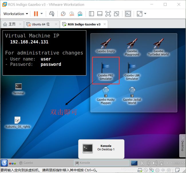
打开pr2 Gazebo,如下在虚拟机中桌面打开
参考 "开始使用 gazebo" 和 "模拟 turtlebot"中的步骤
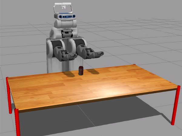
打开环境如下:
从 matlab连接到 ros 网络
在主机上的 matlab 实例中, 运行以下命令在 matlab 中初始化 ros 全局节点, 并通过其 ip 地址ipaddress到虚拟机中的 ros 主机。将 "192.168.245.130" 替换为虚拟机的 ip 地址。
ipaddress = '192.168.244.131'; rosinit(ipaddress);
为机器人手臂发送命令创建操作客户端
在此任务中, 将关节轨迹发送到 pr2 臂。手臂可以通过 ros 的行动来控制。关节轨迹是为每个手臂手动指定的, 并通过单独的操作客户端作为单独的目标消息发送。
创建一个 ros 简单的操作客户端来发送目标消息来移动机器人的右臂。返回rosactionclient和目标消息。等待客户端连接到 ros 操作服务器。
[rArm, rGoalMsg] = rosactionclient('r_arm_controller/joint_trajectory_action');
waitForServer(rArm);
目标消息是一个trajectory_msgs/JointTrajectoryPoint。每个轨迹点应指定关节的位置和速度。
disp(rGoalMsg)
ROS JointTrajectoryGoal message with properties: MessageType: 'pr2_controllers_msgs/JointTrajectoryGoal' Trajectory: [1×1 JointTrajectory]
disp(rGoalMsg.Trajectory)
ROS JointTrajectory message with properties: MessageType: 'trajectory_msgs/JointTrajectory' Header: [1×1 Header] JointNames: {0×1 cell} Points: [0×1 JointTrajectoryPoint]
设置关节名称以匹配 pr2 机器人关节名称。请注意, 有7个关节需要控制。要查找 pr2 右臂中的关节, 请在虚拟机终端中键入以下命令:rosparam get /r_arm_controller/joints
rGoalMsg.Trajectory.JointNames = {'r_shoulder_pan_joint', ...
                                   'r_shoulder_lift_joint', ...
                                   'r_upper_arm_roll_joint', ...
                                   'r_elbow_flex_joint',...
                                   'r_forearm_roll_joint',...
                                   'r_wrist_flex_joint',...
                                   'r_wrist_roll_joint'};
通过创建 rostrajectory_msgs/JointTrajectoryPoint
消息并指定所有7个关节的位置和速度作为矢量, 在臂关节轨迹中创建设定值。将开始时的时间指定为 ros 持续时间对象。
% Point 1
tjPoint1 = rosmessage('trajectory_msgs/JointTrajectoryPoint');
tjPoint1.Positions = zeros(1,7);%七个关节位置都为0
tjPoint1.Velocities = zeros(1,7);%速度位1
tjPoint1.TimeFromStart = rosduration(1.0);

% Point 2
tjPoint2 = rosmessage('trajectory_msgs/JointTrajectoryPoint');
tjPoint2.Positions = [-1.0 0.2 0.1 -1.2 -1.5 -0.3 -0.5];%七个关节位置
tjPoint2.Velocities = zeros(1,7);
tjPoint2.TimeFromStart = rosduration(2.0);
创建具有轨迹中的点的对象数组, 并将其分配给目标消息。使用操作客户端发送目标。 sendGoalAndWait执行, 直到 pr2 手臂完成执行轨迹
rGoalMsg.Trajectory.Points = [tjPoint1,tjPoint2]; %右臂轨迹点从Point1到Point2.
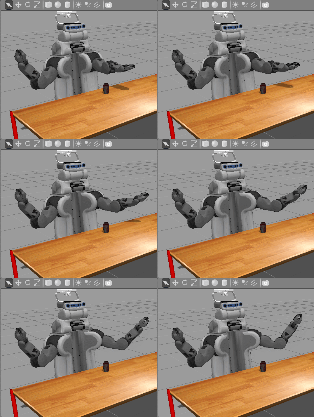
sendGoalAndWait(rArm,rGoalMsg); 发送消息后右臂移动
创建另一个操作客户端, 将命令发送到左臂。指定 pr2 机器人的关节名称。
[lArm, lGoalMsg] = rosactionclient('l_arm_controller/joint_trajectory_action');
waitForServer(lArm);
lGoalMsg.Trajectory.JointNames = {'l_shoulder_pan_joint', ...
                                   'l_shoulder_lift_joint', ...
                                   'l_upper_arm_roll_joint', ...
                                   'l_elbow_flex_joint',...
                                   'l_forearm_roll_joint',...
                                   'l_wrist_flex_joint',...
                                   'l_wrist_roll_joint'};
设置左臂的轨迹点。将其分配给目标消息,并发送目标。
tjPoint3 = rosmessage('trajectory_msgs/JointTrajectoryPoint'); %Point3
tjPoint3.Positions = [1.0 0.2 -0.1 -1.2 1.5 -0.3 0.5]; %目标位置
tjPoint3.Velocities = zeros(1,7); %速度
tjPoint3.TimeFromStart = rosduration(2.0);
lGoalMsg.Trajectory.Points = tjPoint3;
sendGoalAndWait(lArm,lGoalMsg);%发送消息左臂移动
计算末端位置的逆运动学
在本节中, 您将根据所需的末端执行器 (pr2 右夹持器) 位置计算关节的轨迹。robotics.InverseKinematics>类计算所有必需的关节位置, 可以通过操作客户端作为轨迹目标消息发送。 robotics.RigidBodyTree 中的机器人参数、生成配置和可视化机器人。
执行以下步骤:
-
从 ros 网络获取 pr2 机器人的当前状态, 并将其分配给
robotics.RigidBodyTree在 matlab®中与机器人一起工作的硬质 bodytree 对象。 -
定义末端执行器目标姿势。
-
使用这些关节位置可视化机器人配置, 以确保正确的解决方案。
-
使用逆运动学从目标末端效应姿态计算关节位置。
-
将关节位置的轨迹发送到 ros 动作服务器, 以命令实际的 pr2 机器人。
在 matlab®中创建刚体树
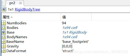
加载 pr2 机器人作为robotics.RigidBodyTree此对象定义机器人的所有运动参数 (包括关节限制)。
pr2 = exampleHelperWGPR2Kinect; %机器人的结构树和显示的可视化文件如下:代码;show(pr2)
获取当前机器人状态
创建一个订阅者, 从机器人中获取关节状态。
jointSub = rossubscriber('joint_states');
获取当前的联合状态消息。
jntState = receive(jointSub);
将联合状态从联合状态消息分配到pr2对象所理解的配置结构的字段。
jntPos = exampleHelperJointMsgToStruct(pr2,jntState);
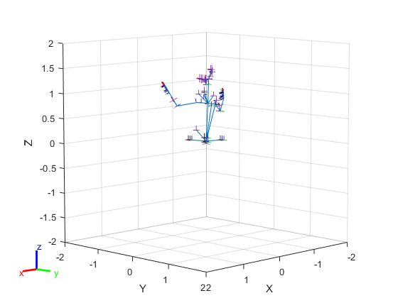
可视化当前机器人配置(从虚拟机得到当前的机器人状态,用Show可视化)
使用 show可视化机器人与给定的关节位置向量。这应该与机器人的当前状态相匹配。代码:show(pr2,jntPos)
创建robotics.InverseKinematics pr2机器人对象的逆变运动学对象。逆运动学的目的是计算 pr2 臂的关节角度, 将夹持器 (即末端执行器) 置于所需的姿势。在一段时间内, 一系列的末端效应器被称为轨迹。
在本例中, 我们将只控制机器人的手臂。因此, 在规划过程中, 我们对抬起关节设置了严格的限制。
torsoJoint = pr2.getBody('torso_lift_link').Joint;
idx = strcmp({jntPos.JointName}, torsoJoint.Name);
torsoJoint.HomePosition = jntPos(idx).JointPosition;
torsoJoint.PositionLimits = jntPos(idx).JointPosition + [-1e-3,1e-3];
创建InverseKinematics对象:
ik = robotics.InverseKinematics('RigidBodyTree', pr2);
禁用随机重新启动以确保安全解决方案一致:
ik.SolverParameters.AllowRandomRestart = false;
为目标姿势的每个组件上的公差指定权重。
weights = [0.25 0.25 0.25 1 1 1];
initialGuess = jntPos; % current jnt pos as initial guess
指定与任务相关的末端效应器姿势。在本例中, pr2 将到达桌上的罐, 抓住罐, 将其移动到不同的位置, 并再次将其设置。我们将使用InverseKinematics对象来规划从一个末端效应姿势顺利过渡到另一个末端效应的运动。
指定末端执行器的名称。
endEffectorName = 'r_gripper_tool_frame';
指定罐的初始 (当前) 姿势和所需的最终姿势。
TCanInitial = trvec2tform([0.7, 0.0, 0.55]);
TCanFinal = trvec2tform([0.6, -0.5, 0.55]);
定义抓取时端部效应器和罐之间所需的相对变换。
TGraspToCan = trvec2tform([0,0,0.08])*eul2tform([pi/8,0,-pi]);
定义所需笛卡尔轨迹的关键航点。罐应该沿着这个轨迹移动。轨迹可以被分解, 如下所示:
-
打开夹持器
-
将末端执行器从当前姿态移动到
T1以便机器人在启动抓握时感到舒适 -
将末端执行器从
T1到TGrasp(准备好抓住) -
合上夹持器, 抓住罐头
-
将末端执行器从
TGraspT2(空气中的提升罐) -
将末端效应器从
T2到T3(可平整移动) -
将末端效应器从
T3移动到TRelease(较低的罐到表表面并准备释放) -
打开抓手, 放开罐头
-
将末端效应器从
TReleaseT4(收回臂)
TGrasp = TCanInitial*TGraspToCan; % The desired end-effector pose when grasping the can
T1 = TGrasp*trvec2tform([0.,0,-0.1]);
T2 = TGrasp*trvec2tform([0,0,-0.2]);
T3 = TCanFinal*TGraspToCan*trvec2tform([0,0,-0.2]);
TRelease = TCanFinal*TGraspToCan; % The desired end-effector pose when releasing the can
T4 = T3*trvec2tform([-0.1,0,0]);
实际运动将由一个序列中的numWaypoints关节位置指定, 并通过 ros 简单动作客户端发送到机器人。这些配置将使用InverseKinematics对象进行选择, 以便将末端效应姿态从初始姿态插值到最终姿势。
执行运动
指定运动的顺序。
motionTask = {'Release', T1, TGrasp, 'Grasp', T2, T3, TRelease, 'Release', T4};
逐一执行motionTask中指定的每个任务。使用指定的帮助器函数发送命令。
for i = 1: length(motionTask)
    if strcmp(motionTask{i}, 'Grasp')
        exampleHelperSendPR2GripperCommand('right',0.0,1000,true);
        continue
    end
    if strcmp(motionTask{i}, 'Release')
        exampleHelperSendPR2GripperCommand('right',0.1,-1,true);
        continue
    end
    Tf = motionTask{i};
    % Get current joint state
    jntState = receive(jointSub);
    jntPos = exampleHelperJointMsgToStruct(pr2, jntState);
    T0 = getTransform(pr2, jntPos, endEffectorName);
    % Interpolating between key waypoints
    numWaypoints = 10;
    TWaypoints = exampleHelperSE3Trajectory(T0, Tf, numWaypoints); % end-effector pose waypoints
    jntPosWaypoints = repmat(initialGuess, numWaypoints, 1); % joint position waypoints
    rArmJointNames = rGoalMsg.Trajectory.JointNames;
    rArmJntPosWaypoints = zeros(numWaypoints, numel(rArmJointNames));
    % Calculate joint position for each end-effector pose waypoint using IK
    for k = 1:numWaypoints
        jntPos = ik(endEffectorName, TWaypoints(:,:,k), weights, initialGuess);
        jntPosWaypoints(k, :) = jntPos;
        initialGuess = jntPos;
        % Extract right arm joint positions from jntPos
        rArmJointPos = zeros(size(rArmJointNames));
        for n = 1:length(rArmJointNames)
            rn = rArmJointNames{n};
            idx = strcmp({jntPos.JointName}, rn);
            rArmJointPos(n) = jntPos(idx).JointPosition;
        end
        rArmJntPosWaypoints(k,:) = rArmJointPos';
    end
    % Time points corresponding to each waypoint
    timePoints = linspace(0,3,numWaypoints);
    % Estimate joint velocity trajectory numerically
    h = diff(timePoints); h = h(1);
    jntTrajectoryPoints = repmat(rosmessage('trajectory_msgs/JointTrajectoryPoint'),1,numWaypoints);
    [~, rArmJntVelWaypoints] = gradient(rArmJntPosWaypoints, h);
    for m = 1:numWaypoints
        jntTrajectoryPoints(m).Positions = rArmJntPosWaypoints(m,:);
        jntTrajectoryPoints(m).Velocities = rArmJntVelWaypoints(m,:);
        jntTrajectoryPoints(m).TimeFromStart = rosduration(timePoints(m));
    end
    % Visualize robot motion and end-effector trajectory in MATLAB(R)
    hold on
    for j = 1:numWaypoints
        show(pr2, jntPosWaypoints(j,:),'PreservePlot', false);
        exampleHelperShowEndEffectorPos(TWaypoints(:,:,j));
        drawnow;
        pause(0.1);
    end
    % Send the right arm trajectory to the robot
    rGoalMsg.Trajectory.Points = jntTrajectoryPoints;
    sendGoalAndWait(rArm, rGoalMsg);
end
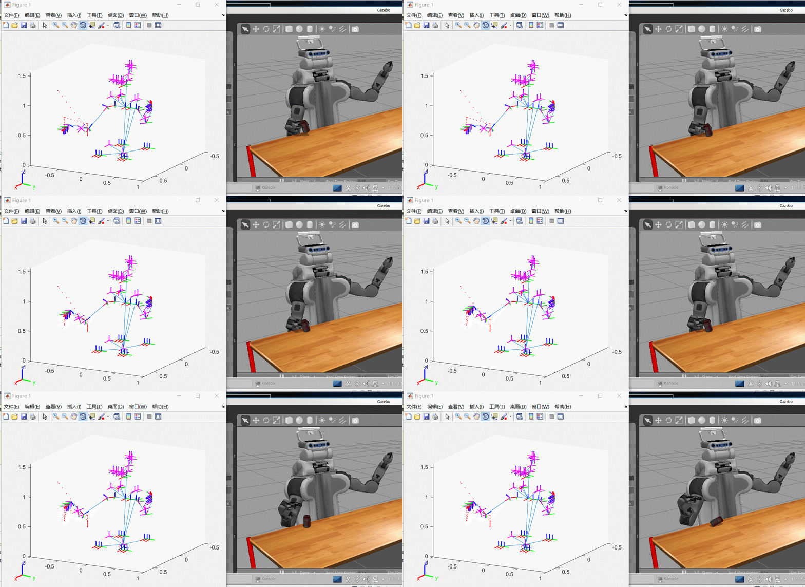
以下为Pick
以下为Place居然倒了。。。。
将手臂移回起始位置。
exampleHelperSendPR2GripperCommand('r',0.0,-1)
rGoalMsg.Trajectory.Points = tjPoint2;
sendGoal(rArm, rGoalMsg);
调用rosshutdown关闭 ros 网络, 并断开与机器人的连接。
rosshutdown
全部代码:
%% Control PR2 Arm Movements Using ROS Actions and Inverse Kinematics
%% Introduction
% This example shows how to send commands to robotic manipulators in MATLAB(R).
% Joint position commands are sent via a ROS action client over a ROS network.
% This example also shows how to calculate joint positions for a desired
% end-effector position. A rigid body tree defines the robot geometry and
% joint constraints, which is used with inverse kinematics to get the robot
% joint positions. You can then send these joint positions as a trajectory
% to command the robot to move.

% Copyright 2016-2018 The MathWorks, Inc.

%% Bring up PR2 Gazebo Simulation
% Spawn PR2 in a simple environment (only with a table and a coke can) in
% Gazebo Simulator. Follow steps in the
% to launch the |Gazebo PR2 Simulator| from the Ubuntu(R) virtual machine desktop.
%
% <>

%% Connect to ROS Network from MATLAB(R)
% In your MATLAB instance on the host computer, run the following commands
% to initialize ROS global node in MATLAB and connect to the ROS master
% in the virtual machine through its IP address |ipaddress|. Replace
% '192.168.245.130' with the IP address of your virtual machine.
%
rosshutdown;
ipaddress = '192.168.244.131';
rosinit(ipaddress);

%% Create Action Clients for Robot Arms and Send Commands
% In this task, you send joint trajectories to the PR2 arms. The arms can be
% controlled via ROS actions. Joint trajectories are manually specified for
% each arm and sent as separate goal messages via separate action clients.

%%
% Create a ROS simple action client to send goal messages to move
% the right arm of the robot. || object
% and goal message are returned. Wait for the client to connect to the ROS action server.

[rArm, rGoalMsg] = rosactionclient('r_arm_controller/joint_trajectory_action');
waitForServer(rArm);

%%
% The goal message is a |trajectory_msgs/JointTrajectoryPoint| message. Each
% trajectory point should specify positions and velocities of the joints.
disp(rGoalMsg)

%%
%       ROS JointTrajectoryGoal message with properties:
%
%         MessageType: 'pr2_controllers_msgs/JointTrajectoryGoal'
%          Trajectory: [1x1 JointTrajectory]
%
%       Use showdetails to show the contents of the message
%

disp(rGoalMsg.Trajectory)

%%
%       ROS JointTrajectory message with properties:
%
%         MessageType: 'trajectory_msgs/JointTrajectory'
%              Header: [1x1 Header]
%          JointNames: {0x1 cell}
%              Points: [0x1 JointTrajectoryPoint]
%
%       Use showdetails to show the contents of the message


%%
% Set the joint names to match the PR2 robot joint names. Note that there
% are 7 joints to control. To find what joints are in PR2 right arm, try
%%
%
%      rosparam get /r_arm_controller/joints
%
%%
% in the virtual machine terminal

rGoalMsg.Trajectory.JointNames = {'r_shoulder_pan_joint', ...
                                   'r_shoulder_lift_joint', ...
                                   'r_upper_arm_roll_joint', ...
                                   'r_elbow_flex_joint',...
                                   'r_forearm_roll_joint',...
                                   'r_wrist_flex_joint',...
                                   'r_wrist_roll_joint'};

%%
% Create setpoints in the arm joint trajectory by creating ROS
% |trajectory_msgs/JointTrajectoryPoint| messages and specifying the
% position and velocity of all 7 joints as a vector. Specify a time from
% the start as a ROS duration object.

% Point 1
tjPoint1 = rosmessage('trajectory_msgs/JointTrajectoryPoint');
tjPoint1.Positions = zeros(1,7);
tjPoint1.Velocities = zeros(1,7);
tjPoint1.TimeFromStart = rosduration(1.0);

% Point 2
tjPoint2 = rosmessage('trajectory_msgs/JointTrajectoryPoint');
tjPoint2.Positions = [-1.0 0.2 0.1 -1.2 -1.5 -0.3 -0.5];
tjPoint2.Velocities = zeros(1,7);
tjPoint2.TimeFromStart = rosduration(2.0);

%%
% Create an object array with the points in the trajectory and assign it to
% the goal message. Send the goal using the action client. The ||
% function will block execution until the PR2 arm finishes executing the trajectory
rGoalMsg.Trajectory.Points = [tjPoint1,tjPoint2];
sendGoalAndWait(rArm,rGoalMsg);

%%
rGoalMsg.Trajectory.Points = tjPoint1;
sendGoalAndWait(rArm,rGoalMsg);
%%
rGoalMsg.Trajectory.Points = tjPoint2;
sendGoalAndWait(rArm,rGoalMsg);

%%
%
% <>
%
%%
% Create another action client to send commands to the left arm. Specify
% the joint names of the PR2 robot.

[lArm, lGoalMsg] = rosactionclient('l_arm_controller/joint_trajectory_action');
waitForServer(lArm);

lGoalMsg.Trajectory.JointNames = {'l_shoulder_pan_joint', ...
                                   'l_shoulder_lift_joint', ...
                                   'l_upper_arm_roll_joint', ...
                                   'l_elbow_flex_joint',...
                                   'l_forearm_roll_joint',...
                                   'l_wrist_flex_joint',...
                                   'l_wrist_roll_joint'};

%%
% Set a trajectory point for the left arm. Assign it to the goal message
% and send the goal.

tjPoint3 = rosmessage('trajectory_msgs/JointTrajectoryPoint');
tjPoint3.Positions = [1.0 0.2 -0.1 -1.2 1.5 -0.3 0.5];
tjPoint3.Velocities = zeros(1,7);
tjPoint3.TimeFromStart = rosduration(2.0);

lGoalMsg.Trajectory.Points = tjPoint3;

sendGoalAndWait(lArm,lGoalMsg);

%%
%
% <>
%
%% Calculate Inverse Kinematics for an End-Effector Position
% In this section, you calculate a trajectory for joints based on the desired end-effector
% (PR2 right gripper) positions. The |robotics.InverseKinematics>| class calculates all the required
% joint positions, which can be sent as a trajectory goal message
% via the action client. A || class is used to define the
% robot parameters, generate configurations, and visualize the robot in
% MATLAB(R).
%
% Perform The following steps:
%
% * Get the current state of the PR2 robot from the ROS network and assign it
% to a |robotics.RigidBodyTree| object to work with the robot in MATLAB(R).
%
% * Define an end-effector goal pose.
%
% * Visualize the robot configuration using these joint positions to ensure
% a proper solution.
%
% * Use inverse kinematics to calculate joint positions from goal end-effector
% poses.
%
% * Send the trajectory of joint positions to the ROS action server to
% command the actual PR2 robot.


%% Create a Rigid Body Tree in MATLAB(R)
% Load a PR2 robot as a |robotics.RigidBodyTree| object. This object defines all the
% kinematic parameters (including joint limits) of the robot.
pr2 = exampleHelperWGPR2Kinect;%关节树
show(pr2)
%% Get the Current Robot State
% Create a subscriber to get joint states from the robot.

jointSub = rossubscriber('joint_states');

%%
% Get the current joint state message.
jntState = receive(jointSub);
% Assign the joint positions from the joint states message to the fields of
% a configuration struct that the |pr2| object understands.
jntPos = exampleHelperJointMsgToStruct(pr2, jntState);


%%  Visualize the Current Robot Configuration
% Use || to visualize the robot with the given joint position vector.
% This should match the current state of the robot.
figure
show(pr2,jntPos)
%%
%
% <>
%

%%
% Create an |robotics.InverseKinematics| object from the |pr2| robot object.
% The goal of inverse kinematics is to calculate the joint
% angles for the PR2 arm that places the gripper (i.e. the end-effector)
% in a desired pose. A sequence of end-effector poses over a period of time
% is called a trajectory.

% In this example we will only be controlling the robot's arms. Therefore
% we place tight limits on the torso-lift joint during planning.
torsoJoint = pr2.getBody('torso_lift_link').Joint;
idx = strcmp({jntPos.JointName}, torsoJoint.Name);
torsoJoint.PositionLimits = jntPos(idx).JointPosition + [-1e-3,1e-3];

% Create the |InverseKinematics| object.
ik = robotics.InverseKinematics('RigidBodyTree', pr2);

% Disable random restart to ensure consistent IK solutions
ik.SolverParameters.AllowRandomRestart = false;

% Specify weights for the tolerances on each component of the goal pose.
weights = [0.25 0.25 0.25 1 1 1];
initialGuess = jntPos; % current jnt pos as initial guess


%%
% Specify end-effector poses related to the task. In this example, PR2 will reach
% to the can on the table, grasp the can, move it to a different location
% and set it down again. We will use the |InverseKinematics| object to plan
% motions that smoothly transition from one end-effector pose to another.

% Specify the name of the end effector
endEffectorName = 'r_gripper_tool_frame';
% Can's initial (current) pose and the desired final pose (There is a
% translation between the two poses along the table top)
TCanInitial = trvec2tform([0.7, 0.0, 0.55]);
TCanFinal = trvec2tform([0.6, -0.5, 0.55]);

% Define the desired relative transform between the end-effector and the can
% when grasping
TGraspToCan = trvec2tform([0,0,0.08])*eul2tform([pi/8,0,-pi]);

%%
% Define the key waypoints of a desired Cartesian trajectory. The can should
% move along this trajectory. The trajectory can be broken up as follows:
% (note each variable starting with a |T| represents an SE3 pose)
%
% * Open the gripper
%
% * Move the end-effector from current pose to |T1| so that the robot will
% feel comfortable to initiate the grasp
%
% * Move the end-effector from |T1| to |TGrasp| (ready to grasp)
%
% * Close the gripper and grab the can
%
% * Move the end-effector from |TGrasp| to |T2| (lift can in the air)
%
% * Move the end-effector from |T2| to |T3| (move can levelly)
%
% * Move the end-effector from |T3| to |TRelease| (lower can to table surface and ready to release)
%
% * Open the gripper and let go of the can
%
% * Move the end-effector from |TRelease| to |T4| (retract arm)
TGrasp = TCanInitial*TGraspToCan; % The desired end-effector pose when grasping the can
T1 = TGrasp*trvec2tform([0.,0,-0.1]);
T2 = TGrasp*trvec2tform([0,0,-0.2]);
T3 = TCanFinal*TGraspToCan*trvec2tform([0,0,-0.2]);
TRelease = TCanFinal*TGraspToCan; % The desired end-effector pose when releasing the can
T4 = T3*trvec2tform([-0.1,0,0]);

%%
% The actual motion will be specified by |numWaypoints| joint
% positions in a sequence and sent to the robot through the ROS simple action
% client. These configurations will be chosen using the
% |InverseKinematics| object such that the end effector pose is
% interpolated from the initial pose to the final pose.

%% Execute the Motion

% Collection of tasks
motionTask = {'Release', T1, TGrasp, 'Grasp', T2, T3, TRelease, 'Release', T4};

% Execute each task specified in motionTask one by one
for i = 1: length(motionTask)
    disp(i)
    if strcmp(motionTask{i}, 'Grasp')
        exampleHelperSendPR2GripperCommand('right',0.0,1000,true);
        continue
    end

    if strcmp(motionTask{i}, 'Release')
        exampleHelperSendPR2GripperCommand('right',0.1,-1,true);
        continue
    end

    Tf = motionTask{i};
    % Get current joint state
    jntState = receive(jointSub);
    jntPos = exampleHelperJointMsgToStruct(pr2, jntState);

    T0 = getTransform(pr2, jntPos, endEffectorName);

    % Interpolating between key waypoints
    numWaypoints = 10;
    TWaypoints = exampleHelperSE3Trajectory(T0, Tf, numWaypoints); % end-effector pose waypoints
    jntPosWaypoints = repmat(initialGuess, numWaypoints, 1); % joint position waypoints

    rArmJointNames = rGoalMsg.Trajectory.JointNames;
    rArmJntPosWaypoints = zeros(numWaypoints, numel(rArmJointNames));

    % Calculate joint position for each end-effector pose waypoint using IK
    for k = 1:numWaypoints
        jntPos = ik(endEffectorName, TWaypoints(:,:,k), weights, initialGuess);
        jntPosWaypoints(k, :) = jntPos;
        initialGuess = jntPos;

        % Extract right arm joint positions from jntPos
        rArmJointPos = zeros(size(rArmJointNames));
        for n = 1:length(rArmJointNames)
            rn = rArmJointNames{n};
            idx = strcmp({jntPos.JointName}, rn);
            rArmJointPos(n) = jntPos(idx).JointPosition;
        end
        rArmJntPosWaypoints(k,:) = rArmJointPos';
    end

    % Time points corresponding to each waypoint
    timePoints = linspace(0,3,numWaypoints);

    % Estimate joint velocity trajectory numerically
    h = diff(timePoints); h = h(1);
    jntTrajectoryPoints = repmat(rosmessage('trajectory_msgs/JointTrajectoryPoint'),1,numWaypoints);
    [~, rArmJntVelWaypoints] = gradient(rArmJntPosWaypoints, h);
    for m = 1:numWaypoints
        jntTrajectoryPoints(m).Positions = rArmJntPosWaypoints(m,:);
        jntTrajectoryPoints(m).Velocities = rArmJntVelWaypoints(m,:);
        jntTrajectoryPoints(m).TimeFromStart = rosduration(timePoints(m));
    end

    % Visualize robot motion and end-effector trajectory in MATLAB(R)
    hold on
    for j = 1:numWaypoints
        show(pr2, jntPosWaypoints(j,:),'PreservePlot', false);
        exampleHelperShowEndEffectorPos(TWaypoints(:,:,j));
        drawnow;
        pause(0.1);
    end

    % Send the right arm trajectory to the robot
    rGoalMsg.Trajectory.Points = jntTrajectoryPoints;
    sendGoalAndWait(rArm, rGoalMsg);

end

%%
%
% <>
%
%%
%
% <>
%


%% Wrap Up
%%
% Move arm back to starting position
exampleHelperSendPR2GripperCommand('r',0.0,-1)
rGoalMsg.Trajectory.Points = tjPoint2;
sendGoal(rArm, rGoalMsg);

%%
% Call |rosshutdown| to shutdown ROS network and disconnect from the robot.
rosshutdown
displayEndOfDemoMessage(mfilename)
