ARFoundation之路-平面管理
平面检测是很多AR应用的基础,无论是ARKit还是ARCore,都提供平面检测功能。同时,平面也是可跟踪对象,在前几节中我们知道,ARFoundation使用ARPlaneManager管理器来管理平面。
(一)平面检测管理
AR中检测平面的原理:ARFoundation对摄像机获取的图像进行处理,分离图像中的特征点(这些特征点往往都是图像中明暗、强弱、颜色变化较大的点),利用VIO和IMU跟踪这些特征点的三维空间信息,在跟踪过程中,对特征点信息进行处理,并尝试用空间中位置相近或者符合一定规律的特征点构建平面,如果成功就是检测出了平面。平面有其位置、方向和边界信息,ARPlaneManager负责如何检测平面以及管理这些检测出来的平面,但它并不负责渲染平面。
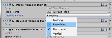
在ARPlaneManager中,我们可以设置平面检测的方式,如水平平面(Horizontal)、垂直平面(Vertical)、水平平面&垂直平面(Everything)或者不检测平面(Nothing),因为检测平面也是一个消耗性能的工作,所以根据应用需要选择合适的检测方式可以优化应用性能,如下图所示。
ARPlaneManager每帧都会进行平面检测,会添加新检测到的平面、更新现有平面、移除过时的平面。当一个新的平面被检测到时,ARPlaneManager会实例化一个平面Prefab来表示该平面,如果开发中ARPlaneManager的Plane Prefab属性没有对赋值,ARPlaneManager将会实例化一个空对象,并在这个空对象上挂载ARPlane组件,ARPlane组件包含了该平面的相关信息数据。
ARPlaneManager组件还有一个planesChanged事件,开发人员可以注册这个事件,以便在平面发生改变时进行相应处理。
(二)可视化平面
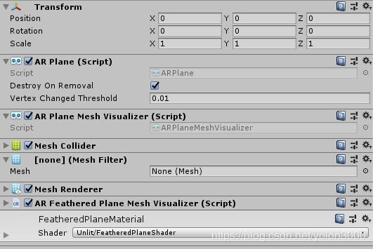
在ARFoundation中,ARPlaneManager并不负责平面的可视化渲染,而由其Plane Prefab属性指定的预制体负责。在前文中,我们新建了一个AR Default Plane对象作为预制体,该预制体上挂载了如下图所示组件。
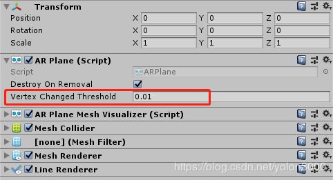
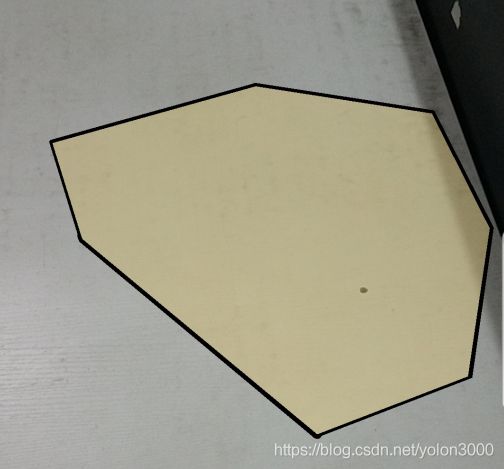
AR Plane组件负责该平面各类属性事宜,如是否在移除平面时销毁该实例化对象,控制可划分为同一平面的特征点的阀值(上图中红框属性,只有偏差在这个阀值内的特征点才可归属为同一平面,这影响平面检测。);AR Plane Mesh Visualizer该组件主要是从边界特征点和其他特征点三角化生成一个平面网格,有这个平面网格后自然就可以使用Mesh Renderer采用合适材质渲染出来了;默认平面预制体还有一个Line Renderer,它负责渲染平面可视化后的边界连线。所以使用默认平面预制体可视已检测到的平面如下图所示。
(三)个性化可视平面
对已检测到的平面默认的可视化显得有些生硬和突兀,有时我们需要更加友好的界面,这时我们就需要对已检测到的平面定制我们自己个性的可视方案。
为达到更好的视觉效果,处理的思路如下:
1)、不显示黑色边框;
2)、重新制作一个渲染材质和Shader脚本,纹理我们使用半透明的PNG,Shader脚本渲染这个半透明的纹理,将纹理空白区域都镂空;
3)、编写一个渐隐的脚本,让边缘的纹理渐隐,达到更好的视觉过渡。
按照以上思路,我们直接对AR Default Plane预制体进行改造。
1)、删除AR Default Plane预制体上的Line Renderer组件;
2)、编写如下所示Shader,制作一张PNG半透明纹理,并新建一个利用这个Shader的材质。
Shader "Unlit/FeatheredPlaneShader"
{
	Properties
	{
		_MainTex ("Texture", 2D) = "white" {}
		_TexTintColor("Texture Tint Color", Color) = (1,1,1,1)
		_PlaneColor("Plane Color", Color) = (1,1,1,1)
	}
	SubShader
	{
		Tags { "RenderType"="Transparent" "Queue"="Transparent" }
		LOD 100
		Blend SrcAlpha OneMinusSrcAlpha
		ZWrite Off

		Pass
		{
			CGPROGRAM
			#pragma vertex vert
			#pragma fragment frag

			#include "UnityCG.cginc"

			struct appdata
			{
				float4 vertex : POSITION;
				float2 uv : TEXCOORD0;
				float3 uv2 : TEXCOORD1;
			};

			struct v2f
			{
				float4 vertex : SV_POSITION;
				float2 uv : TEXCOORD0;
				float3 uv2 : TEXCOORD1;
			};

			sampler2D _MainTex;
			float4 _MainTex_ST;
			fixed4 _TexTintColor;
			fixed4 _PlaneColor;
			float _ShortestUVMapping;

			v2f vert (appdata v)
			{
				v2f o;
				o.vertex = UnityObjectToClipPos(v.vertex);
				o.uv = TRANSFORM_TEX(v.uv, _MainTex);
				o.uv2 = v.uv2;
				return o;
			}

			fixed4 frag (v2f i) : SV_Target
			{
				fixed4 col = tex2D(_MainTex, i.uv) * _TexTintColor;
				col = lerp( _PlaneColor, col, col.a);
				// Fade out from as we pass the edge.
				// uv2.x stores a mapped UV that will be "1" at the beginning of the feathering.
				// We fade until we reach at the edge of the shortest UV mapping.
				// This is the remmaped UV value at the vertex.
				// We choose the shorted one so that ll edges will fade out completely.
				// See ARFeatheredPlaneMeshVisualizer.cs for more details.
				col.a *=  1-smoothstep(1, _ShortestUVMapping, i.uv2.x);
				return col;
			}
			ENDCG
		}
	}
}
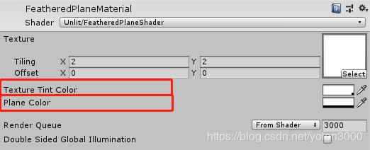
在这个Shader中,有三个参数,Texture即为纹理,将我们制作的纹理赋给它,TextureTintColor为纹理显示,我们要让透明的十字星号显示出来,Alpha设置为220,PlaneColor为平面的背景色,这里我们不要背景色,Alpha设置为0,如下图所示。
3)、新建一个C#脚本文件,命名为ARFeatheredPlaneMeshVisualizer.cs,编写如下代码:
using System.Collections.Generic;
using UnityEngine;
using UnityEngine.XR.ARFoundation;
/// ARPlaneMeshVisualizer has a meshUpdated event that can be used to modify the generated
/// mesh. In this case we'll add UV2s to mark the boundary vertices.
/// This technique avoids having to generate extra vertices for the boundary. It works best when the plane is
/// is fairly uniform.
///
/// The Mesh generated by ARPlaneMeshVisualizer
void GenerateBoundaryUVs(Mesh mesh)
{
int vertexCount = mesh.vertexCount;
// Reuse the list of UVs
s_FeatheringUVs.Clear();
if (s_FeatheringUVs.Capacity < vertexCount) { s_FeatheringUVs.Capacity = vertexCount; }
mesh.GetVertices(s_Vertices);
Vector3 centerInPlaneSpace = s_Vertices[s_Vertices.Count - 1];
Vector3 uv = new Vector3(0, 0, 0);
float shortestUVMapping = float.MaxValue;
// Assume the last vertex is the center vertex.
for (int i = 0; i < vertexCount - 1; i++)
{
float vertexDist = Vector3.Distance(s_Vertices[i], centerInPlaneSpace);
// Remap the UV so that a UV of "1" marks the feathering boudary.
// The ratio of featherBoundaryDistance/edgeDistance is the same as featherUV/edgeUV.
// Rearrange to get the edge UV.
float uvMapping = vertexDist / Mathf.Max(vertexDist - featheringWidth, 0.001f);
uv.x = uvMapping;
// All the UV mappings will be different. In the shader we need to know the UV value we need to fade out by.
// Choose the shortest UV to guarentee we fade out before the border.
// This means the feathering widths will be slightly different, we again rely on a fairly uniform plane.
if (shortestUVMapping > uvMapping) { shortestUVMapping = uvMapping; }
s_FeatheringUVs.Add(uv);
}
m_FeatheredPlaneMaterial.SetFloat("_ShortestUVMapping", shortestUVMapping);
// Add the center vertex UV
uv.Set(0, 0, 0);
s_FeatheringUVs.Add(uv);
mesh.SetUVs(1, s_FeatheringUVs);
mesh.UploadMeshData(false);
}
static List<Vector3> s_FeatheringUVs = new List<Vector3>();
static List<Vector3> s_Vertices = new List<Vector3>();
ARPlaneMeshVisualizer m_PlaneMeshVisualizer;
ARPlane m_Plane;
Material m_FeatheredPlaneMaterial;
}
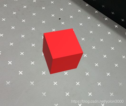
将ARFeatheredPlaneMeshVisualizer挂载到AR Default Plane预制体上,完成之后应该如下图所示:
编译运行,效果如下所示,视觉效果要好很多了。
注:本文Shader与ARFeatheredPlaneMeshVisualizer.cs脚本均取自参考代码工程,为方便读者,我已将图片、Shader、脚本分离出来,读者也可以在 这里 下载,直接就可以在工程里使用。
参考代码
arfoundation-samples arfoundation-samples