TM4C129建立FREERTOS工程
写下这篇教程的原因主要是自己当初学习TM4C129使用FREERTOS操作系统时,发现TI只提供了TM4C123G的移植工程而没有提供TM4C129的,并且网络上教程比较少,而且有很多的教程存在问题,因此把自己当初建立 FREERTOS操作系统的过程写成一个教程,供大家参考。
FREERTOS操作系统介绍
FREERTOS是免费的、自由的、不受约束的操作系统。
操作系统允许多个任务同时运行,这个叫做多任务,实际上,一个处理核心在某一个时刻只能运行一个任务,操作系统中任务调度器的责任就是决定在某一个时刻究竟运行哪个任务,任务调度在各个任务之间的切换非常快,这就给人们造成了同一个时刻有多个任务同时运行的错觉。
操作系统源码下载
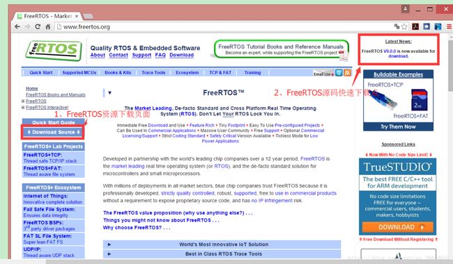
进入FREERTOS官网下载源码

下载得到一个.exe文件,安装后实际上是一个文件夹,里面存放着FREERTOS的源码及一些相关的移植好的工程。

点开FREERTOS中的Source文件夹就是我们的FREERTOS源码了。

FREERTOS移植
一、添加源码
1.首先需要新建一个空白工程,详见TM4129新建工程
2.在工程中新建一个FREERTOS文件夹

3.将FREERTOS源码移植到该文件夹中

4.注意!portable文件夹只需要留下keil,MemMang和RVDS三个文件夹

二、在工程中添加文件
1.打开新建好的工程,新建分组FREERTOS_CORE和FREERTOS_PORTABLE,然后向这两个分组中添加文件

2.注意!这里heap_4.c是第四种内存管理办法,一共有5中内存管理办法,原理不同,各有利弊。
三、添加相应的头文件路径
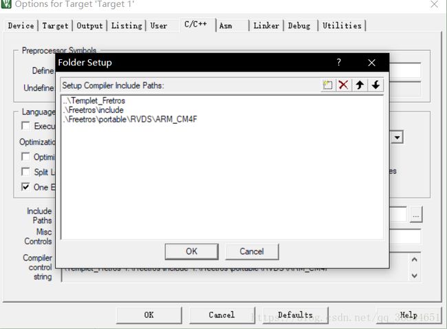
1.添加完文件后,还要添加其源码的头文件路径

2.添加FreeRTOSConfig.h文件
在TM4123G提供的FREERTOS例程中可以找到该文件,我这里也可以提供一个链接
3.FreeRTOS里面有许多定义,包括系统时钟,滴答时钟等等,更多的详细说明可以参考原子资料FREERTOS开发手册
4.注意!开发手册里面提到了关于钩子函数编译错误的问题,我在实际开发中也遇到了此问题,文中提到了解决办法,请读者有机会一定要读一读这个开发手册,虽然此开发是针对STM32,但也只是在建立工程时有所区别,后面的学习都可以跟着此开发手册来。
四、修改Startup.s文件
Startup.s文件是系统的启动文件,主要包括堆和栈的初始化配置、中断向量表的配置以及将程序引导到main( )函数等。Startup.s主要完成三个工作:栈和堆的初始化、定位中断向量表、调用Reset Handler
有关Startup.s文件的介绍,推荐看下这篇博客
我们需要把文件修改为如下格式:
; <<< Use Configuration Wizard in Context Menu >>>
;******************************************************************************
;
; startup_rvmdk.S - Startup code for use with Keil's uVision.
;
; Copyright (c) 2013-2017 Texas Instruments Incorporated.  All rights reserved.
; Software License Agreement
;
; Texas Instruments (TI) is supplying this software for use solely and
; exclusively on TI's microcontroller products. The software is owned by
; TI and/or its suppliers, and is protected under applicable copyright
; laws. You may not combine this software with "viral" open-source
; software in order to form a larger program.
;
; THIS SOFTWARE IS PROVIDED "AS IS" AND WITH ALL FAULTS.
; NO WARRANTIES, WHETHER EXPRESS, IMPLIED OR STATUTORY, INCLUDING, BUT
; NOT LIMITED TO, IMPLIED WARRANTIES OF MERCHANTABILITY AND FITNESS FOR
; A PARTICULAR PURPOSE APPLY TO THIS SOFTWARE. TI SHALL NOT, UNDER ANY
; CIRCUMSTANCES, BE LIABLE FOR SPECIAL, INCIDENTAL, OR CONSEQUENTIAL
; DAMAGES, FOR ANY REASON WHATSOEVER.
;
; This is part of revision 2.1.4.178 of the EK-TM4C1294XL Firmware Package.
;
;******************************************************************************

;******************************************************************************
;
; <o> Stack Size (in Bytes) <0x0-0xFFFFFFFF:8>
;
;******************************************************************************
Stack   EQU     0x00000200

;******************************************************************************
;
; <o> Heap Size (in Bytes) <0x0-0xFFFFFFFF:8>
;
;******************************************************************************
Heap    EQU     0x00000000

;******************************************************************************
;
; Allocate space for the stack.
;
;******************************************************************************
        AREA    STACK, NOINIT, READWRITE, ALIGN=3
StackMem
        SPACE   Stack
__initial_sp

;******************************************************************************
;
; Allocate space for the heap.
;
;******************************************************************************
        AREA    HEAP, NOINIT, READWRITE, ALIGN=3
__heap_base
HeapMem
        SPACE   Heap
__heap_limit

;******************************************************************************
;
; Indicate that the code in this file preserves 8-byte alignment of the stack.
;
;******************************************************************************
        PRESERVE8

;******************************************************************************
;
; Place code into the reset code section.
;
;******************************************************************************
        AREA    RESET, CODE, READONLY
        THUMB

;******************************************************************************
;
; External declarations for the interrupt handlers used by the application.
;
;******************************************************************************
        EXTERN  xPortPendSVHandler
        EXTERN  vPortSVCHandler
        EXTERN  xPortSysTickHandler
;******************************************************************************
;
; The vector table.
;
;******************************************************************************
        EXPORT  __Vectors
__Vectors
        DCD     StackMem + Stack            ; Top of Stack
        DCD     Reset_Handler               ; Reset Handler
        DCD     NmiSR                       ; NMI Handler
        DCD     FaultISR                    ; Hard Fault Handler
        DCD     IntDefaultHandler           ; The MPU fault handler
        DCD     IntDefaultHandler           ; The bus fault handler
        DCD     IntDefaultHandler           ; The usage fault handler
        DCD     0                           ; Reserved
        DCD     0                           ; Reserved
        DCD     0                           ; Reserved
        DCD     0                           ; Reserved
        DCD     vPortSVCHandler             ; SVCall handler
        DCD     IntDefaultHandler           ; Debug monitor handler
        DCD     0                           ; Reserved
        DCD     xPortPendSVHandler          ; The PendSV handler
        DCD     xPortSysTickHandler         ; The SysTick handler
        DCD     IntDefaultHandler           ; GPIO Port A
        DCD     IntDefaultHandler           ; GPIO Port B
        DCD     IntDefaultHandler           ; GPIO Port C
        DCD     IntDefaultHandler           ; GPIO Port D
        DCD     IntDefaultHandler           ; GPIO Port E
        DCD     IntDefaultHandler           ; UART0 Rx and Tx
        DCD     IntDefaultHandler           ; UART1 Rx and Tx
        DCD     IntDefaultHandler           ; SSI0 Rx and Tx
        DCD     IntDefaultHandler           ; I2C0 Master and Slave
        DCD     IntDefaultHandler           ; PWM Fault
        DCD     IntDefaultHandler           ; PWM Generator 0
        DCD     IntDefaultHandler           ; PWM Generator 1
        DCD     IntDefaultHandler           ; PWM Generator 2
        DCD     IntDefaultHandler           ; Quadrature Encoder 0
        DCD     IntDefaultHandler           ; ADC Sequence 0
        DCD     IntDefaultHandler           ; ADC Sequence 1
        DCD     IntDefaultHandler           ; ADC Sequence 2
        DCD     IntDefaultHandler           ; ADC Sequence 3
        DCD     IntDefaultHandler           ; Watchdog timer
        DCD     IntDefaultHandler           ; Timer 0 subtimer A
        DCD     IntDefaultHandler           ; Timer 0 subtimer B
        DCD     IntDefaultHandler           ; Timer 1 subtimer A
        DCD     IntDefaultHandler           ; Timer 1 subtimer B
        DCD     IntDefaultHandler           ; Timer 2 subtimer A
        DCD     IntDefaultHandler           ; Timer 2 subtimer B
        DCD     IntDefaultHandler           ; Analog Comparator 0
        DCD     IntDefaultHandler           ; Analog Comparator 1
        DCD     IntDefaultHandler           ; Analog Comparator 2
        DCD     IntDefaultHandler           ; System Control (PLL, OSC, BO)
        DCD     IntDefaultHandler           ; FLASH Control
        DCD     IntDefaultHandler           ; GPIO Port F
        DCD     IntDefaultHandler           ; GPIO Port G
        DCD     IntDefaultHandler           ; GPIO Port H
        DCD     IntDefaultHandler           ; UART2 Rx and Tx
        DCD     IntDefaultHandler           ; SSI1 Rx and Tx
        DCD     IntDefaultHandler           ; Timer 3 subtimer A
        DCD     IntDefaultHandler           ; Timer 3 subtimer B
        DCD     IntDefaultHandler           ; I2C1 Master and Slave
        DCD     IntDefaultHandler           ; Quadrature Encoder 1
        DCD     IntDefaultHandler           ; CAN0
        DCD     IntDefaultHandler           ; CAN1
        DCD     0                           ; Reserved
        DCD     0                           ; Reserved
        DCD     IntDefaultHandler           ; Hibernate
        DCD     IntDefaultHandler           ; USB0
        DCD     IntDefaultHandler           ; PWM Generator 3
        DCD     IntDefaultHandler           ; uDMA Software Transfer
        DCD     IntDefaultHandler           ; uDMA Error
        DCD     IntDefaultHandler           ; ADC1 Sequence 0
        DCD     IntDefaultHandler           ; ADC1 Sequence 1
        DCD     IntDefaultHandler           ; ADC1 Sequence 2
        DCD     IntDefaultHandler           ; ADC1 Sequence 3
        DCD     0                           ; Reserved
        DCD     0                           ; Reserved
        DCD     IntDefaultHandler           ; GPIO Port J
        DCD     IntDefaultHandler           ; GPIO Port K
        DCD     IntDefaultHandler           ; GPIO Port L
        DCD     IntDefaultHandler           ; SSI2 Rx and Tx
        DCD     IntDefaultHandler           ; SSI3 Rx and Tx
        DCD     IntDefaultHandler           ; UART3 Rx and Tx
        DCD     IntDefaultHandler           ; UART4 Rx and Tx
        DCD     IntDefaultHandler           ; UART5 Rx and Tx
        DCD     IntDefaultHandler           ; UART6 Rx and Tx
        DCD     IntDefaultHandler           ; UART7 Rx and Tx
        DCD     0                           ; Reserved
        DCD     0                           ; Reserved
        DCD     0                           ; Reserved
        DCD     0                           ; Reserved
        DCD     IntDefaultHandler           ; I2C2 Master and Slave
        DCD     IntDefaultHandler           ; I2C3 Master and Slave
        DCD     IntDefaultHandler           ; Timer 4 subtimer A
        DCD     IntDefaultHandler           ; Timer 4 subtimer B
        DCD     0                           ; Reserved
        DCD     0                           ; Reserved
        DCD     0                           ; Reserved
        DCD     0                           ; Reserved
        DCD     0                           ; Reserved
        DCD     0                           ; Reserved
        DCD     0                           ; Reserved
        DCD     0                           ; Reserved
        DCD     0                           ; Reserved
        DCD     0                           ; Reserved
        DCD     0                           ; Reserved
        DCD     0                           ; Reserved
        DCD     0                           ; Reserved
        DCD     0                           ; Reserved
        DCD     0                           ; Reserved
        DCD     0                           ; Reserved
        DCD     0                           ; Reserved
        DCD     0                           ; Reserved
        DCD     0                           ; Reserved
        DCD     0                           ; Reserved
        DCD     IntDefaultHandler           ; Timer 5 subtimer A
        DCD     IntDefaultHandler           ; Timer 5 subtimer B
        DCD     IntDefaultHandler           ; Wide Timer 0 subtimer A
        DCD     IntDefaultHandler           ; Wide Timer 0 subtimer B
        DCD     IntDefaultHandler           ; Wide Timer 1 subtimer A
        DCD     IntDefaultHandler           ; Wide Timer 1 subtimer B
        DCD     IntDefaultHandler           ; Wide Timer 2 subtimer A
        DCD     IntDefaultHandler           ; Wide Timer 2 subtimer B
        DCD     IntDefaultHandler           ; Wide Timer 3 subtimer A
        DCD     IntDefaultHandler           ; Wide Timer 3 subtimer B
        DCD     IntDefaultHandler           ; Wide Timer 4 subtimer A
        DCD     IntDefaultHandler           ; Wide Timer 4 subtimer B
        DCD     IntDefaultHandler           ; Wide Timer 5 subtimer A
        DCD     IntDefaultHandler           ; Wide Timer 5 subtimer B
        DCD     IntDefaultHandler           ; FPU
        DCD     0                           ; Reserved
        DCD     0                           ; Reserved
        DCD     IntDefaultHandler           ; I2C4 Master and Slave
        DCD     IntDefaultHandler           ; I2C5 Master and Slave
        DCD     IntDefaultHandler           ; GPIO Port M
        DCD     IntDefaultHandler           ; GPIO Port N
        DCD     IntDefaultHandler           ; Quadrature Encoder 2
        DCD     0                           ; Reserved
        DCD     0                           ; Reserved
        DCD     IntDefaultHandler           ; GPIO Port P (Summary or P0)
        DCD     IntDefaultHandler           ; GPIO Port P1
        DCD     IntDefaultHandler           ; GPIO Port P2
        DCD     IntDefaultHandler           ; GPIO Port P3
        DCD     IntDefaultHandler           ; GPIO Port P4
        DCD     IntDefaultHandler           ; GPIO Port P5
        DCD     IntDefaultHandler           ; GPIO Port P6
        DCD     IntDefaultHandler           ; GPIO Port P7
        DCD     IntDefaultHandler           ; GPIO Port Q (Summary or Q0)
        DCD     IntDefaultHandler           ; GPIO Port Q1
        DCD     IntDefaultHandler           ; GPIO Port Q2
        DCD     IntDefaultHandler           ; GPIO Port Q3
        DCD     IntDefaultHandler           ; GPIO Port Q4
        DCD     IntDefaultHandler           ; GPIO Port Q5
        DCD     IntDefaultHandler           ; GPIO Port Q6
        DCD     IntDefaultHandler           ; GPIO Port Q7
        DCD     IntDefaultHandler           ; GPIO Port R
        DCD     IntDefaultHandler           ; GPIO Port S
        DCD     IntDefaultHandler           ; PWM 1 Generator 0
        DCD     IntDefaultHandler           ; PWM 1 Generator 1
        DCD     IntDefaultHandler           ; PWM 1 Generator 2
        DCD     IntDefaultHandler           ; PWM 1 Generator 3
        DCD     IntDefaultHandler           ; PWM 1 Fault

;******************************************************************************
;
; This is the code that gets called when the processor first starts execution
; following a reset event.
;
;******************************************************************************
        EXPORT  Reset_Handler
Reset_Handler
        ;
        ; Enable the floating-point unit.  This must be done here to handle the
        ; case where main() uses floating-point and the function prologue saves
        ; floating-point registers (which will fault if floating-point is not
        ; enabled).  Any configuration of the floating-point unit using
        ; DriverLib APIs must be done here prior to the floating-point unit
        ; being enabled.
        ;
        ; Note that this does not use DriverLib since it might not be included
        ; in this project.
        ;
        MOVW    R0, #0xED88
        MOVT    R0, #0xE000
        LDR     R1, [R0]
        ORR     R1, #0x00F00000
        STR     R1, [R0]

        ;
        ; Call the C library enty point that handles startup.  This will copy
        ; the .data section initializers from flash to SRAM and zero fill the
        ; .bss section.
        ;
        IMPORT  __main
        B       __main

;******************************************************************************
;
; This is the code that gets called when the processor receives a NMI.  This
; simply enters an infinite loop, preserving the system state for examination
; by a debugger.
;
;******************************************************************************
NmiSR
        B       NmiSR

;******************************************************************************
;
; This is the code that gets called when the processor receives a fault
; interrupt.  This simply enters an infinite loop, preserving the system state
; for examination by a debugger.
;
;******************************************************************************
FaultISR
        B       FaultISR

;******************************************************************************
;
; This is the code that gets called when the processor receives an unexpected
; interrupt.  This simply enters an infinite loop, preserving the system state
; for examination by a debugger.
;
;******************************************************************************
IntDefaultHandler
        B       IntDefaultHandler

;******************************************************************************
;
; Make sure the end of this section is aligned.
;
;******************************************************************************
        ALIGN

;******************************************************************************
;
; Some code in the normal code section for initializing the heap and stack.
;
;******************************************************************************
        AREA    |.text|, CODE, READONLY

;******************************************************************************
;
; The function expected of the C library startup code for defining the stack
; and heap memory locations.  For the C library version of the startup code,
; provide this function so that the C library initialization code can find out
; the location of the stack and heap.
;
;******************************************************************************
    IF :DEF: __MICROLIB
        EXPORT  __initial_sp
        EXPORT  __heap_base
        EXPORT  __heap_limit
    ELSE
        IMPORT  __use_two_region_memory
        EXPORT  __user_initial_stackheap
__user_initial_stackheap
        LDR     R0, =HeapMem
        LDR     R1, =(StackMem + Stack)
        LDR     R2, =(HeapMem + Heap)
        LDR     R3, =StackMem
        BX      LR
    ENDIF

;******************************************************************************
;
; Make sure the end of this section is aligned.
;
;******************************************************************************
        ALIGN

;******************************************************************************
;
; Tell the assembler that we're done.
;
;******************************************************************************
        END
这里面添加了许多外设以及和FREERTOS时钟控制有关的定义。有兴趣的可以研究一下。
五、修改代码
将代码修改如下
led.c:
//*****************************************************************************
//
// led_task.c - A simple flashing LED task.
//
// Copyright (c) 2012-2017 Texas Instruments Incorporated. All rights reserved.
// Software License Agreement
//
// Texas Instruments (TI) is supplying this software for use solely and
// exclusively on TI's microcontroller products. The software is owned by
// TI and/or its suppliers, and is protected under applicable copyright
// laws. You may not combine this software with "viral" open-source
// software in order to form a larger program.
//
// THIS SOFTWARE IS PROVIDED "AS IS" AND WITH ALL FAULTS.
// NO WARRANTIES, WHETHER EXPRESS, IMPLIED OR STATUTORY, INCLUDING, BUT
// NOT LIMITED TO, IMPLIED WARRANTIES OF MERCHANTABILITY AND FITNESS FOR
// A PARTICULAR PURPOSE APPLY TO THIS SOFTWARE. TI SHALL NOT, UNDER ANY
// CIRCUMSTANCES, BE LIABLE FOR SPECIAL, INCIDENTAL, OR CONSEQUENTIAL
// DAMAGES, FOR ANY REASON WHATSOEVER.
//
// This is part of revision 2.1.4.178 of the EK-TM4C123GXL Firmware Package.
//
//*****************************************************************************
#include main .c:
//*****************************************************************************
//
// blinky.c - Simple example to blink the on-board LED.
//
// Copyright (c) 2013-2017 Texas Instruments Incorporated. All rights reserved.
// Software License Agreement
//
// Texas Instruments (TI) is supplying this software for use solely and
// exclusively on TI's microcontroller products. The software is owned by
// TI and/or its suppliers, and is protected under applicable copyright
// laws. You may not combine this software with "viral" open-source
// software in order to form a larger program.
//
// THIS SOFTWARE IS PROVIDED "AS IS" AND WITH ALL FAULTS.
// NO WARRANTIES, WHETHER EXPRESS, IMPLIED OR STATUTORY, INCLUDING, BUT
// NOT LIMITED TO, IMPLIED WARRANTIES OF MERCHANTABILITY AND FITNESS FOR
// A PARTICULAR PURPOSE APPLY TO THIS SOFTWARE. TI SHALL NOT, UNDER ANY
// CIRCUMSTANCES, BE LIABLE FOR SPECIAL, INCIDENTAL, OR CONSEQUENTIAL
// DAMAGES, FOR ANY REASON WHATSOEVER.
//
// This is part of revision 2.1.4.178 of the EK-TM4C1294XL Firmware Package.
//
//*****************************************************************************
#include 编译下载即可。
最后,附上我自己完成好的工程。
例程