HDLBits:在线学习 Verilog (十二 · Problem 55 - 59)
本系列内容来自于知乎专栏,链接如下:https://zhuanlan.zhihu.com/c_1131528588117385216
本系列文章将和读者一起巡礼数字逻辑在线学习网站 HDLBits 的教程与习题,并附上解答和一些作者个人的理解,相信无论是想 7 分钟精通 Verilog,还是对 Verilog 和数电知识查漏补缺的同学,都能从中有所收获。
Problem 55 Ring or vibrate
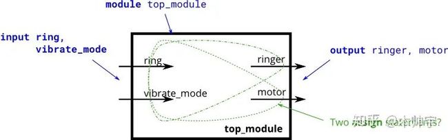
假设你正在设计一个电路来控制手机的振铃器和振动电机。当手机来电时(input ring),电路必须把震动( output motor = 1 )或响铃( output ringer = 1 )打开,但不能同时打开。当手机处于震动模式时( input vibrate = 1 ),则打开震动( output motor = 1 )。否则打开响铃。
我们尝试仅适用assign语句来实现该组合电路。
设计思路(加粗)
此处为本问题的中心内容,也是整个电路设计时的重要思路,我尽量给各位初学者表达清楚。
硬件电路的编程与软件的变成是存在差异的,一般进行软件编程时,我们是先关注输入( if (input are _)),再关注输出( then (output are ))。而在硬件编程时,我们需要转变思维方式,在确保输出是正确的情况下,再思考输入。( The (output should be _) when (inputs are __))。
本题所述的要求十分适合以软件编程的命令形式来编写程序( if ring then do this ),所以我们需要试着来转变思维,用硬件的设计思路来编写该程序( assign ringer = )。
能够思考和转换两种风格是硬件设计所需的最重要技能之一。
(本次练习期望仅使用两行语句)
tips: 我们应该思考只有当.....时,输出motor才为高。停止软件编程思维( if (vibrate mode ) then ....)
//Module Declaration

module top_module (
    input ring,
    input vibrate_mode,
    output ringer,       // Make sound
    output motor         // Vibrate
);

    assign motor = ring & vibrate_mode;
    assign ringer  = ring & (!vibrate_mode);

endmodule
Problem 56 Thermostat
一个冷/热恒温控制器可以同时在冬季和夏季对温度进行调节。设计一个电路,根据需要打开和关闭加热器、空调和鼓风机风扇。(本题可参照Problem 55 )
恒温器可以处于两种模式之一:制热(mode = 1)和制冷(mode = 0)。在制热模式下,当温度过低时(too_cold = 1),打开加热器,但不要使用空调。在制冷模式下,当温度过高(too_hot = 1)打开空调,但不要打开加热器。当加热器或空调打开时,也打开风扇使空气循环。此外,即使加热器和空调关闭,用户也可以请求将风扇打开(fan_on = 1)。
尝试仅使用assign语句来设计该电路,可参考Problem 55
(本次练习期望仅使用三行语句)
//Module Declaration

module top_module
(
    input too_cold,
    input too_hot,
    input mode,
    input fan_on,
    output heater,
    output aircon,
    output fan
);

assign heater = mode  & too_cold;
assign aircon = !mode & too_hot;
assign fan    = (mode & too_cold) | (!mode & too_hot) | fan_on;

endmodule
Problem 57 3-bit population count
设计一个电路来计算输入中 ‘ 1 ’ 个数。
//Module Declaration
module top_module
 (
     input [2:0] in,
     output [1:0] out
 );
解析如下:
module top_module(
    input [2:0] in,
    output [1:0] out );

    always @(*)
        begin
        out = 2'b00;
            for(integer i = 0; i<3; i++)
                begin
                    if(in[i] == 1'b1)
                        out = out + 1'b1;
                end
        end

endmodule
Problem 58 Gates and vectors
有一个4bit输入的电路,我们需要了解4bit输入数据之间的关系。
out_both: 输入的每一个bit均需要检测该bit位与其左侧(即高比特位)是否全为 ‘ 1 ’ 。示例:
out_both[2]应检测in[2]与in[3]是否均为 ‘ 1 ’ 。因为in[3]为输入的最高位,故我们无需检测out_both[3]out_any: 输入的每一个bit均需要检测该bit位与其右侧(即低比特位)两者其中一个为 ‘ 1 ’ 。示例:
out_any[2]应检测in[2]与in[1]两者其中一个为 ‘ 1 ’ 。因为in[0]为输入的最低位,故我们无需检测out_any[0]out_different: 输入的每一个bit均需要检测该bit位与其左侧(即高比特位)两者是否不同。示例:
out_different[2]应检测in[2]与in[3]两者是否不同 。在本节中,我们将输入变成一个环,所以in[3]的左侧为in[0]。
Module Declaration
module top_module(
    input [3:0] in,
    output [2:0] out_both,
    output [3:1] out_any,
    output [3:0] out_different );
解析如下:
module top_module(
    input [3:0] in,
    output [2:0] out_both,
    output [3:1] out_any,
    output [3:0] out_different);

    assign out_both      = {
     {in[3] & in[2]}, {in[2] & in[1]}, {in[1] & in[0]}};
    assign out_any       = {
     {in[3] | in[2]} , {in[2] | in[1]} , {in[1] | in[0]}};
    assign out_different = {
     {in[0] ^ in[3]}, {in[3] ^ in[2]}, {in[2] ^ in[1]}, {in[1] ^ in[0]}};

endmodule
Problem 59 Even longer vectors
该题与P58类似,仅将输入从4bit改为100bit ( input [99:0] ),题目的其余要求均相同。
(本次练习期望仅使用三行语句)
Module Declaration
module top_module(
    input [99:0] in,
    output [98:0] out_both,
    output [99:1] out_any,
    output [99:0] out_different );
题目要求我们采用三句assign语句来实现该电路的功能,参考P58。
out_both输出是判断现有bit位与其左侧bit位是否均为 ‘1’,可以采用移位运算来实现,
in[98] in[97] in[96] in[95] ......... in[3] in[2] in[1] in[0]
in[99] in[98] in[97] in[96] ......... in[4] in[3] in[2] in[1]
out_any输出是判断现有bit位与右侧bit位两者间是否有一个为‘1’,也采用移位运算:
in[99] in[98] in[97] in[96] ......... in[4] in[3] in[2] in[1]
in[98] in[97] in[96] in[95] ......... in[3] in[2] in[1] in[0]
out_different输出同理,判断现有bit位与左侧bit位是否不同,唯一需要注意的是在此输出中题目要求将输入变为一个环,将in[0] 与 in[99] 链接在一起了,此处可采用链接符 { in[0], in[99:1] }。该输出同样采用移位运算。
in[99] in[98] in[97] in[96] ......... in[3] in[2] in[1] in[0]
in[0] in[99] in[98] in[97] ......... in[4] in[3] in[2] in[1]
解析如下:
module top_module(
    input [99:0] in,
    output [98:0] out_both,
    output [99:1] out_any,
    output [99:0] out_different );

    assign out_both = in[98:0] & in[99:1];
    assign out_any  = in[99:1] | in[98:0];
    assign out_different = in ^ {in[0],in[99:1]};

endmodule
【打个广告】
各位对数字IC和FPGA设计感兴趣的盆友们,我们搭建了一个QQ交流群。经过这一段时间的发展,群聊中已经有将近900个志同道合的同学加入。QQ群里已经整理了许多的资料,其中包含有视频,资料,教程,芯片手册,软件安装包,虚拟机环境。覆盖了从FPGA开发,数字前端,电路设计等等一系列的内容。QQ群号为:810689010 ,进群暗号:公众号。欢迎进群交流!
为了能让这个群长期发展下去,用于支付扩建群聊所需的会员费,无奈将这个群设置成付费入群,仅需一元即可,多谢大家支持。
QQ群二维码

 期待与您的添加!
‧‧‧‧‧‧‧‧‧‧‧‧‧‧‧‧ END ‧‧‧‧‧‧‧‧‧‧‧‧‧‧‧‧

长按识别图中二维码关注
欢迎关注微信公众号【数字积木】,更精彩的内容等着你!