Revit SDK 介绍:CompoundStructure 复合结构
前言
本文介绍 Revit 复合结构,及 SDK 中的例子, CompoundStructure。
内容
概念说明
复合结构
墙、楼板、天花板和屋顶可以由平行的层构成。
复合图元既可以由单一材质的连续图层构成(例如胶合板),也可以由多重图层组成(例如石膏板、龙骨、隔热层、气密层、砖和壁板)。 另外,构件内的每个层都有其特殊的用途。 例如,有些层用于结构支座,而另一些层则用于隔热。 Revit 会考虑每个图层的功能,并通过匹配功能优先顺序在相邻的复合结构中连接对应的图层。
可以通过设置层的材质、厚度和功能来表示各层。 当视图的详细程度设置为“中等”或“精细”时,会显示复合图元的图层。 复合结构中图层之间的线使用图元的公共边子类别进行显示。 替换主体图层以在复合结构中额外控制图层的显示。 在“粗略”详细程度,仅显示复合图元的边界。 在复合图元的类型属性中,可以设置粗略比例填充样式和粗略比例填充颜色。
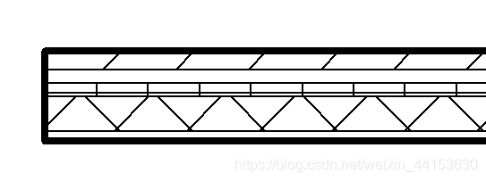
通常可以在楼层平面、天花板投影平面及剖面中观察此复合几何图形。 在以下示例中,七层墙体显示在平面视图中。
SDK 例子效果
先看运行前后的效果,然后思考如何通过 UI 界面设置,最后再想想如何通过 API 来设置。
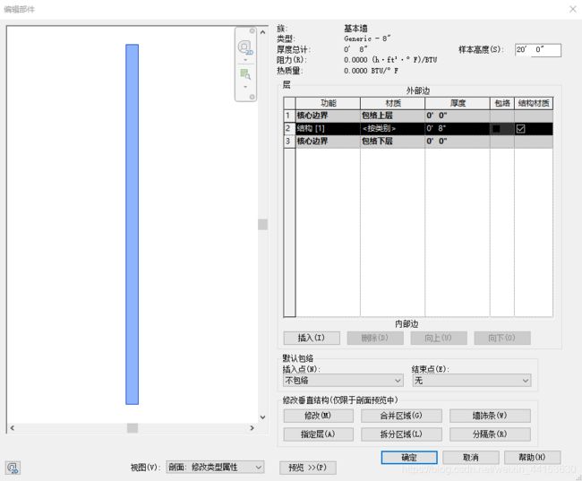
运行前:

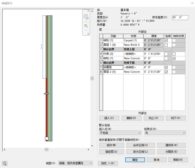
运行后(例子中,没有给最左边上面的区域设置材质,我自己手动设置了材质以便区分):

代码逻辑
步骤:
- 得到墙的复合结构以进行操作
- 添加墙的各个面层
- 设置各个层的功能和属性
- 切割最左边的层
- 添加墙饰条和分隔条
得到墙的复合结构以进行操作
复合结构,CompoundStructure,是墙的类型的一部分。
WallType wallType = wall.WallType;
CompoundStructure wallCS = wallType.GetCompoundStructure();
添加墙的各个面层
创建面层,然后将其设置到复合结构中。
面层创建接口,类CompoundStructureLayer:
public CompoundStructureLayer(double width, MaterialFunctionAssignment function, ElementId materialId);
创建 5 个面层:
List<CompoundStructureLayer> csLayers = new List<CompoundStructureLayer>();
CompoundStructureLayer finish1Layer = new CompoundStructureLayer(0.2, MaterialFunctionAssignment.Finish1, masonry_Brick.Id);
CompoundStructureLayer substrateLayer = new CompoundStructureLayer(0.1, MaterialFunctionAssignment.Substrate, ElementId.InvalidElementId);
CompoundStructureLayer structureLayer = new CompoundStructureLayer(0.5, MaterialFunctionAssignment.Structure, concrete.Id);
CompoundStructureLayer membraneLayer = new CompoundStructureLayer(0, MaterialFunctionAssignment.Membrane, ElementId.InvalidElementId);
CompoundStructureLayer finish2Layer = new CompoundStructureLayer(0.2, MaterialFunctionAssignment.Finish2, concrete.Id);
csLayers.Add(finish1Layer);
csLayers.Add(substrateLayer);
csLayers.Add(structureLayer);
csLayers.Add(membraneLayer);
csLayers.Add(finish2Layer);
设置面层:
wallCS.SetLayers(csLayers);
设置各个层的功能和属性
设置结构层和内外表面层,以及层包络:
wallCS.StructuralMaterialIndex = 2;
wallCS.SetNumberOfShellLayers(ShellLayerType.Interior, 2);
wallCS.SetNumberOfShellLayers(ShellLayerType.Exterior, 1);
wallCS.SetParticipatesInWrapping(0, false);
切割最左边的层
例子中的切割写的比较随意,实际上它并没有明确去切割最左边的层,只是最终效果是切割了最左边的层。
关键语句:
int newRegionId = wallCS.SplitRegion(splitUV, splitOrientation);
这是用来真正做分区的那一行代码,第一个参数,UV gridUV,是与墙的切面平行的面上的坐标,或者说是立面上的坐标,可以看成你从类型属性对话框中看到的那个平面坐标系。第二个参数值方向,RectangularGridSegmentOrientation splitDirection,实际就是 U 和 V 方向:
public enum RectangularGridSegmentOrientation
{

    // 垂直
    Vertical = 0,
    // 水平
    Horizontal = 1
}
用上面设置层次的方法的结果,墙在里面的左下角是 UV(0,0) 原点。
回到 SDK 例子中,先得到 0 号分割的Id,各个分割可以理解成各个区域的边界,所以一个分割可能对应一个或者多个区域:
int segId = wallCS.GetSegmentIds()[0];
得到对应的区域,这里虽然是for 循环,实际上只有一个:
foreach (int regionId in wallCS.GetAdjacentRegions(segId))
{

   // 得到某个分割在某个区域的起始点和结束点
   UV endPoint1 = UV.Zero;
   UV endPoint2 = UV.Zero;
   wallCS.GetSegmentEndPoints(segId, regionId, out endPoint1, out endPoint2);

   // 对这个区域进行分割
   RectangularGridSegmentOrientation splitOrientation = (RectangularGridSegmentOrientation)(((int)(wallCS.GetSegmentOrientation(segId)) + 1) % 2);
   UV splitUV = (endPoint1 + endPoint2) / 2.0;
   int newRegionId = wallCS.SplitRegion(splitUV, splitOrientation);
   // 检验分割是否成功
   bool isValidRegionId = wallCS.IsValidRegionId(newRegionId);
   // 其它代码
   // ....
}
添加墙饰条和分隔条
SDK 中关于墙饰条位置的计算,非常的无厘头,毫无意义,就不赘述了,抽取关键点。
准备墙饰条的属性设置,在API中墙饰条和分隔条都是用 WallSweepInfo 来表示:
private void PrepareWallSweepInfo(WallSweepInfo wallSweepInfo, double distance)
{

   wallSweepInfo.DistanceMeasuredFrom = DistanceMeasuredFrom.Base;
   wallSweepInfo.Distance = distance;
   wallSweepInfo.WallSide = WallSide.Exterior;
   wallSweepInfo.Id = -1;
   wallSweepInfo.WallOffset = -0.1;
}
进行墙饰条设置:
WallSweepInfo sweepInfo = new WallSweepInfo(true, WallSweepType.Sweep);
PrepareWallSweepInfo(sweepInfo, sweepPoint.V);
// Set sweep profile: Sill-Precast : 8" Wide
sweepInfo.ProfileId = GetProfile("8\" Wide").Id;
sweepInfo.Id = 101;
wallCS.AddWallSweep(sweepInfo);
// Create a WallSweepInfo for wall reveal
WallSweepInfo revealInfo = new WallSweepInfo(true, WallSweepType.Reveal);
PrepareWallSweepInfo(revealInfo, revealPoint.U);
revealInfo.Id = 102;
wallCS.AddWallSweep(revealInfo);
个人感受
CompoundStructure 复合结构,体现了 Revit 墙的强大功能。不过使用起来,有些不便,因为各个区域的位置关系需要开发者自己来查找,API 是不会告诉你对应位置关系的,也就是说开发者要自己根据接口,获取数据来管理,segement,region,layer 以及他们之间的关系的信息。


