三层架构实验
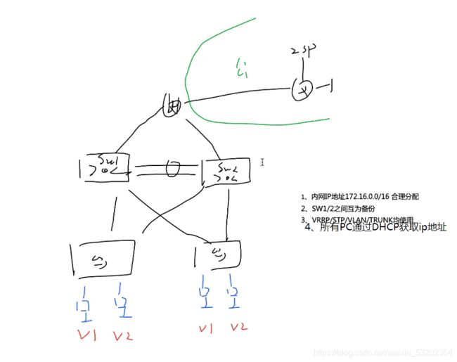
题目要求:

根据图片先在ensp上设计出拓扑:

分析部署思路,首先根据题目网段进行子网划分,然后把简单的一些要求先配置了,比如将sw1和sw2间链路合并,然后配置交换部分,如给每个交换机创建vlan1 2(vlan1默认存在,所以只需要创建vlan2),然后将交换机间接口调为trunk,然后将接口划入vlan,再就是给每个交换机配置生成树(STP),将vlan分别划入不同的组里面,然后就是svi设置,给俩台三层交换机分别设置vlan1和valn2的虚拟网关和备用网关vrrp(网关冗余)并设置优先级和上行链路追踪,再就是给三层交换机开启DHCP服务,最后再路由部分,使用ospf,将路由器设为area0,三层交换机部分设为area1,配置路由和缺省,最后再给路由器开启nat服务,可以连接外网就完成了。
1.子网划分
题目给的网段是172.16.0.0/24,我们汇聚层,让上俩个为三层交换机,2个vlan互为主备,下面俩个交换机为二层交换机,pc1 3在vlan1中,pc2 4在vlan中,所以:
我们可以给干路网段172.16.0.0/30
vlan1:172.16.2.0/24
vlan2:172.16.3.0/24
2.Eth-Trunk
将交换机sw1和交换机sw2之间的俩条线路合并。
[sw1]interface Eth-Trunk 0
[sw1]interface GigabitEthernet 0/0/1
[sw1-GigabitEthernet0/0/1]eth-trunk 0
Info: This operation may take a few seconds. Please wait for a moment...done.
[sw1]interface GigabitEthernet 0/0/2
[sw1-GigabitEthernet0/0/2]eth-trunk 0
Info: This operation may take a few seconds. Please wait for a moment...done.
[sw2]interface Eth-Trunk 0
[sw2]interface GigabitEthernet 0/0/1
[sw2-GigabitEthernet0/0/1]eth-trunk 0
Info: This operation may take a few seconds. Please wait for a moment...done
[sw2]interface GigabitEthernet 0/0/2
[sw2-GigabitEthernet0/0/2]eth-trunk 0
Info: This operation may take a few seconds. Please wait for a moment...done.
3.创建vlan,划分接口,交换机链路全为trunk
vlan1默认存在,默认通过,不需要创建和划分trunk。sw3 4和电脑连接链路为access。
[sw1]vlan 2
[sw2]vlan 2
[sw3]vlan 2
[sw4]vlan 2
[sw1]interface Eth-Trunk 0
[sw1-Eth-Trunk0]port link-type trunk
[sw1-Eth-Trunk0]port trunk allow-pass vlan 2
[sw1]interface GigabitEthernet 0/0/4
[sw1-GigabitEthernet0/0/4]port link-type trunk
[sw1-GigabitEthernet0/0/4]port trunk allow-pass vlan 2
[sw1]interface GigabitEthernet 0/0/5
[sw1-GigabitEthernet0/0/5]port link-type trunk
[sw1-GigabitEthernet0/0/5]port trunk allow-pass vlan 2
[sw2]interface Eth-Trunk 0
[sw2-Eth-Trunk0]port link-type trunk
[sw2-Eth-Trunk0]port trunk allow-pass vlan 2
[sw2]interface GigabitEthernet 0/0/4
[sw2-GigabitEthernet0/0/4]port link-type trunk
[sw2-GigabitEthernet0/0/4]port trunk allow-pass vlan 2
[sw2]interface GigabitEthernet 0/0/5
[sw2-GigabitEthernet0/0/5]port link-type trunk
[sw2-GigabitEthernet0/0/5]port trunk allow-pass vlan 2
[sw3]interface Eth0/0/3
[sw3-Ethernet0/0/3]port link-type access
[sw3-Ethernet0/0/3]port default vlan 2
[sw3]interface Eth 0/0/1
[sw3-Ethernet0/0/1]port link-type trunk
[sw3-Ethernet0/0/1]port trunk allow-pass vlan 2
[sw3]interface Eth 0/0/4
[sw3-Ethernet0/0/4]port link-type trunk
[sw3-Ethernet0/0/4]port trunk allow-pass vlan 2
[sw4]interface Eth 0/0/3
[sw4-Ethernet0/0/3]port link-type access
[sw4-Ethernet0/0/3]port default vlan 2
[sw4]interface Eth 0/0/1
[sw4-Ethernet0/0/1]port link-type trunk
[sw4-Ethernet0/0/1]port trunk allow-pass vlan 2
[sw4]interface Eth 0/0/4
[sw4-Ethernet0/0/4]port link-type trunk
[sw4-Ethernet0/0/4]port trunk allow-pass vlan 2
4.生成树(STP)的设置,且sw1为vlan1(组1)中sw1给根网桥,sw2为备用,vlan2(组2)中,sw2为根网桥,sw1为备用
[sw1]stp enable
[sw1]stp mode mstp
[sw1]stp region-configuration
[sw1-mst-region]region-name redhat
[sw1-mst-region]instance 1 vlan 1
[sw1-mst-region]instance 2 vlan 2
[sw1-mst-region]active region-configuration
Info: This operation may take a few seconds. Please wait for a moment...done.

[sw2]stp enable
[sw2]stp mode mstp
[sw2]stp region-configuration
[sw2-mst-region]region-name redhat
[sw2-mst-region]instance 1 vlan 1
[sw2-mst-region]instance 2 vlan 2
[sw2-mst-region]active region-configuration
Info: This operation may take a few seconds. Please wait for a moment...done.

[sw3]stp enable
[sw3]stp mode mstp
[sw3]stp region-configuration
[sw3-mst-region]region-name redhat
[sw3-mst-region]instance 1 vlan 1
[sw3-mst-region]instance 2 vlan 2
[sw3-mst-region]active region-configuration
Info: This operation may take a few seconds. Please wait for a moment...done.

[sw4]stp enable
[sw4]stp mode mstp
[sw4]stp region-configuration
[sw4-mst-region]region-name redhat
[sw4-mst-region]instance 1 vlan 1
[sw4-mst-region]instance 2 vlan 2
[sw4-mst-region]active region-configuration
Info: This operation may take a few seconds. Please wait for a moment...done.

[sw1]stp instance 1 root
[sw1]stp instance 2 root secondary
[sw2]stp instance 2 root
[sw2]stp instance 1 root secondary
然后我们可以将二层交换机sw3 4的stp加速开启(stp edged-port)
[sw3]interface Eth 0/0/2
[sw3-Ethernet0/0/2]stp edged-port enable
[sw3-Ethernet0/0/2]quit
[sw3]interface Eth 0/0/3
[sw3-Ethernet0/0/3]stp edged-port enable

[sw4]interface Eth 0/0/2
[sw4-Ethernet0/0/2]stp edged-port enable
[sw4-Ethernet0/0/2]quit
[sw4]interface Eth 0/0/3
[sw4-Ethernet0/0/3]stp edged-port enable
[sw4-Ethernet0/0/3]quit
5.三层交换机虚拟网关(SVI)和备用网关冗余(vrrp)的创建
在三层交换机中,给sw1和sw2的valn1和vlan2分别设置网关,并且在sw1上vlan1为主,vlan2为备,在sw2上vlan2为主,vlan1为备。并且在设置vrrp的时候进行上行链路追踪,优先级降10。
[sw1]interface Vlanif 1
[sw1-Vlanif1]ip address 172.16.2.253 24
[sw1]interface Vlanif 2
[sw1-Vlanif2]ip address 172.16.3.253 24

[sw2]interface Vlanif 1
[sw2-Vlanif1]ip address 172.16.2.254 24
[sw2]interface Vlanif 2
[sw2-Vlanif2]ip address 172.16.3.254 24

[sw1]interface Vlanif 1
[sw1-Vlanif1]vrrp vrid 1 virtual-ip 172.16.2.250
[sw1-Vlanif1]vrrp vrid 1 priority 101
[sw1-Vlanif1]vrrp vrid 1 track interface GigabitEthernet 0/0/3 reduced 10
[sw1]interface Vlanif 2
[sw1-Vlanif2]vrrp vrid 1 virtual-ip 172.16.3.250

[sw2]interface Vlanif 2
[sw2-Vlanif2]vrrp vrid 1 virtual-ip 172.16.3.250
[sw2-Vlanif2]vrrp vrid 1 priority 101
[sw2-Vlanif2]vrrp vrid 1 track interface GigabitEthernet 0/0/3 reduced 10
[sw2]interface Vlanif 1
[sw2-Vlanif1]vrrp vrid 1 virtual-ip 172.16.2.250
6.开启DHCP
[sw1]dhcp enable
Info: The operation may take a few seconds. Please wait for a moment.done.
[sw1]ip pool 1
Info:It's successful to create an IP address pool.
[sw1-ip-pool-1]network 172.16.2.0 mask 255.255.255.0
[sw1-ip-pool-1]gateway-list 172.16.2.250
[sw1-ip-pool-1]dns-list 114.114.114.114
[sw1]ip pool 2
Info:It's successful to create an IP address pool.
[sw1-ip-pool-2]network 172.16.3.0 mask 255.255.255.0
[sw1-ip-pool-2]gateway-list 172.16.3.250
[sw1-ip-pool-2]dns-list 114.114.114.114
[sw1]interface Vlanif 1
[sw1-Vlanif1]dhcp select global
[sw1]interface Vlanif 2
[sw1-Vlanif2]dhcp select global

[sw2]dhcp enable
Info: The operation may take a few seconds. Please wait for a moment.done.
[sw2]ip pool 1
Info:It's successful to create an IP address pool.
[sw2-ip-pool-1]network 172.16.2.0 mask 24
[sw2-ip-pool-1]gateway-list 172.16.2.250
[sw2-ip-pool-1]dns-list 114.114.114.114
[sw2]ip pool 2
Info:It's successful to create an IP address pool.
[sw2-ip-pool-2]network 172.16.3.0 mask 24
[sw2-ip-pool-2]gateway-list 172.16.3.250
[sw2-ip-pool-2]dns-list 114.114.114.114
[sw2]interface Vlanif 1
[sw2-Vlanif1]dhcp select global
[sw2]interface Vlanif 2
[sw2-Vlanif2]dhcp select global
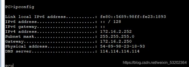
然后到pc上开启dhcp服务,用ipconfig命令获取ipv4地址。

7.路由配置
1.首先给r1和isp接口配置地址
[r1]interface GigabitEthernet 0/0/0
[r1-GigabitEthernet0/0/0]ip address 172.16.0.1 30
[r1]interface GigabitEthernet 0/0/1
[r1-GigabitEthernet0/0/1]ip address 172.16.0.5 30
[r1]interface GigabitEthernet 0/0/2
[r1-GigabitEthernet0/0/2]ip address 12.12.1.1 24

[isp]interface GigabitEthernet 0/0/0
[isp-GigabitEthernet0/0/0]ip address 12.12.1.2 24
[isp]interface LoopBack 1
[isp-LoopBack1]ip address 12.1.1.1 24
2.然后就是三层交换机sw1 2和路由器r1之间的接口了,这里我们说一下,由于三层接口不支持 undo portswitch 所以我们用vlan代替。
[sw1]interface Vlanif 111
[sw1-Vlanif111]ip address 172.16.0.2 30
[sw1]interface GigabitEthernet 0/0/3
[sw1-GigabitEthernet0/0/3]port link-type access
[sw1-GigabitEthernet0/0/3]port default vlan 111
[sw1-GigabitEthernet0/0/3]stp edged-port enable

[sw2]interface Vlanif 222
[sw2-Vlanif222]ip address 172.16.0.6 30
[sw2]interface GigabitEthernet 0/0/3
[sw2-GigabitEthernet0/0/3]port link-type access
[sw2-GigabitEthernet0/0/3]port default vlan 222
[sw2-GigabitEthernet0/0/3]stp edged-port enable
3.再然后就是ospf的配置
我们将路由器部分划为区域0,三层交换机部分划为区域1.
[sw1]ospf 1 router-id 1.1.1.1
[sw1-ospf-1]area 0
[sw1-ospf-1-area-0.0.0.0]network 172.16.0.2 0.0.0.0
[sw1-ospf-1]area 1
[sw1-ospf-1-area-0.0.0.1]network 172.16.2.0 0.0.0.255
[sw1-ospf-1-area-0.0.0.1]network 172.16.3.0 0.0.0.255
[sw1-ospf-1-area-0.0.0.1]abr-summary 172.16.2.0 255.255.224.0

[sw2]ospf 1 router-id 2.2.2.2
[sw2-ospf-1]area 0
[sw2-ospf-1-area-0.0.0.0]network 172.16.0.6 0.0.0.0
[sw2-ospf-1]area 1
[sw2-ospf-1-area-0.0.0.1]network 172.16.2.0 0.0.0.255
[sw2-ospf-1-area-0.0.0.1]network 172.16.3.0 0.0.0.255
[sw2-ospf-1-area-0.0.0.1]abr-summary 172.16.2.0 255.255.254.0

[r1]ospf 1 router-id 3.3.3.3
[r1-ospf-1]area 0
[r1-ospf-1-area-0.0.0.0]network 172.16.0.0 0.0.255.255
4.优化,由于sw1和sw2的只能有vlan1有邻居关系,所以要沉默vlan2和下行俩个接口。
[sw1]ospf 1
[sw1-ospf-1]silent-interface Vlanif 2
[sw1-ospf-1]silent-interface GigabitEthernet 0/0/4
[sw1-ospf-1]silent-interface GigabitEthernet 0/0/5

[sw2]ospf 1
[sw2-ospf-1]silent-interface Vlanif 2
[sw2-ospf-1]silent-interface GigabitEthernet 0/0/4
[sw2-ospf-1]silent-interface GigabitEthernet 0/0/5
5.这些做完之后就是缺省路由了(还需给sw1 2上配置空接口,防止路由黑洞)
[sw1]ip route-static 0.0.0.0 0 12.1.1.2
[sw1]ospf 1
[sw1-ospf-1]default-route-advertise  //下发路由

[sw1]ip route-static 172.16.2.0 23 NULL 0
[sw2]ip route-static 172.16.2.0 23 NULL 0
8.NAT的配置
为了可以isp上网,我们要给路由器r1连接isp的接口配置NAT。
[r1]acl 2000
[r1-acl-basic-2000]rule permit source 172.16.0.0 0.0.255.255
[r1]interface GigabitEthernet 0/0/2
[r1-GigabitEthernet0/0/2]nat outbound 2000
到这里我们的三层架构实验也算是完成了。