LIO-sam:安装 - 运行 - 论文介绍 - 源码阅读
文章目录
- 一. 相关背景介绍
- 二. 安装和运行
-
- 2.1 安装gtsam 4.0.2
- 2.2 安装lio-sam
- 2.3 运行
- 三. 论文介绍
-
- 3.1 背景
- 3.2 方法
-
- 3.2.1 Lidar和IMU坐标系
- 3.2.1 因子图框架介绍
- 3.2.3 IMU因子
- 3.2.4 激光里程计因子
- 3.2.5 GPS因子
- 3.2.6 回环因子
- 四. 源码阅读
-
- 4.1 源码的整体框架
- 4.2 参数解读
- 4.3 utility.h
- 4.4 源码解读
一. 相关背景介绍
LIO-SAM: Tightly-coupled Lidar Inertial Odometry via Smoothing and Mapping
作者Tixiao Shan在2018年发表过LeGO-LOAM,当时他还在史蒂文斯理工学院读博士,2019年毕业之后去了MIT做助理研究员。这篇文章LIO-SAM实际上是LeGO-LOAM的扩展版本,添加了IMU预积分因子和GPS因子,去除了帧帧匹配部分,然后更详细地描述了LeGO-LOAM帧图匹配部分的设计动机和细节。现在论文已经被IROS2020录用,作为高精度,imu,雷达,gps结合,程序还进行了开源,非常值得学习。
-
本人安装环境:ubuntu18.04 + melodic
-
作者github:https://github.com/TixiaoShan/LIO-SAM [论文在:~/LIO-SAM/blob/master/config/doc/paper.pdf
-
数据链接:链接:https://pan.baidu.com/s/1CbDJPIupCm3yROmM2qOsOw 提取码:ato7
二. 安装和运行
2.1 安装gtsam 4.0.2
本人测试这个版本可用,LIO-sam需要gtsam4.0.2的版本,而Lego_slam需要的版本为gtsam4.0.0-alpha2,这两个版本兼容性问题还没解决,目前每次使用都是来回切换版本,有些费时间,有解决的朋友可以评论或者私信一下本人,万分感激~~
如果想要学习gtsam的使用,可以访问链接。
wget -O ~/Downloads/gtsam.zip https://github.com/borglab/gtsam/archive/4.0.2.zip
cd ~/Downloads/ && unzip gtsam.zip -d ~/Downloads/
cd ~/Downloads/gtsam-4.0.2/
mkdir build && cd build
cmake -DGTSAM_BUILD_WITH_MARCH_NATIVE=OFF ..
sudo make install -j16  //根据自己的cpu核数定,越多越快,本人是16核的,注意不能超出自己电脑的核数
2.2 安装lio-sam
这个安装比较常规,下载编译,基本没什么问题。
cd ~/catkin_ws/src
git clone https://github.com/TixiaoShan/LIO-SAM.git
cd ..
catkin_make
2.3 运行
roslaunch lio_sam run.launch
rosbag play casual_walk_2.bag
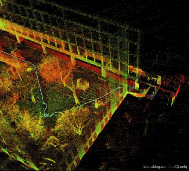
运行结果如下:
三. 论文介绍
3.1 背景
LOAM(lidar odometry and mapping )以低漂移和实时估计的方法而被广泛使用,它在kitti的排名中长期霸榜,尽管它很成功,但是它也有一些自身的缺点。
- LOAM直接存储全局体素地图而不是局部地图,从而很难实现回环,来修正漂移。
- 没有结合GPS等外部测量进行位姿态修正。
- 同时在大规模测试中也会存在误差,因为它的核心是扫描匹配的方法。
LIO-sam采用帧-局部地图匹配的方式代替LOAM的帧-全局地图匹配的方式。属于一种紧耦合的方法。
-
松耦合
LOAM和LeGO:使用IMU去除LiDAR点云的运动畸变,并且使用EKF整合LiDAR和IMU的测量。 -
紧耦合
R-LINS(robocentric lidar-inertial state estimator):使用误差状态卡尔曼滤波器迭代地修正机器人的位姿估计。
LIOM:它是LIO-mapping的缩写,联合优化LiDAR和IMU测量。但是LIOM一次性处理所有测量,因此不能实时运行。 -
作者
属于紧耦合的激光-惯性里程计方法,只是采用了因子图优化而不是滤波的方法。因子图优化通过iSAM2完成。
3.2 方法
-
3.2.1 Lidar和IMU坐标系

3.2.1 因子图框架介绍
- 优化四个因子
- LiDAR里程计因子(绿色):由每个关键帧和之前n个关键帧之间的帧图匹配结果得到。
- IMU预积分因子(橙色):两个相邻关键帧之间的IMU测量积分得到。
- GPS因子(黄色):由每个关键帧的GPS测量得到。
- 回环因子(黑色):由每个关键帧和候选回环关键帧的时序相邻的2m+1个关键帧之间的帧图匹配得到。
因子图模型如下所示:

论文采用MAP(maximum a posterior)来解决非线性优化问题,可以用贝叶斯网络的形式很好的表示,采用了高斯噪声模型,所以我们同样可以添加其他传感器,比如可以测量高度的测高仪、可以测航向的罗盘等。
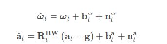
3.2.3 IMU因子
IMU的角速度和加速度:
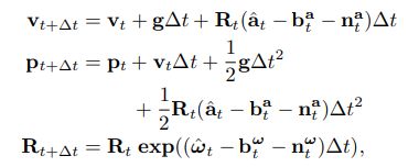
所以预测 t + ∆ t t+∆t t+∆t时刻的速度、位置和旋转角:
i , j i,j i,j时刻的预积分:
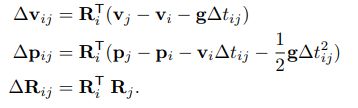
预积分详细可以参考论文:
C. Forster, L. Carlone, F. Dellaert, and D. Scaramuzza, “On-Manifold Preintegration for Real-Time Visual-Inertial Odometry,” IEEE Transactions on Robotics, vol. 33(1): 1-21, 2016.
3.2.4 激光里程计因子
当新的雷达数据来了之后,我们先对它进行特征提取。通过局部区域点的粗糙(凹凸)程度来提取边和平面。
边:点的粗糙程度很大。
平面:点的粗糙程度较小。
把每一帧数据添加进因子图对于计算来说是很困难的,所以本文采用了一种图像中常用的方法:提取关键帧。非关键帧的数据则被丢弃。本文中提取关键帧的位置和旋转角度为 1 m 1m 1m和 1 0 0 10^0 100。
i i i时刻提取的特征表示为 F i = { F i e , F i p } F_i=\{F_i^e,F_i^p\} Fi={ Fie,Fip}。点云匹配和位姿优化过程与LOAM/LeGO-LOAM 相同 。不同的是, 这里使用过去n+1帧关键帧的组合点云而不是全局点云和最新帧进行匹配。具体的特征提取方法可以查看以下论文:
- J. Zhang and S. Singh, “Low-drift and Real-time Lidar Odometry and Mapping,” Autonomous Robots, vol. 41(2): 401-416, 2017.
- T. Shan and B. Englot, “LeGO-LOAM: Lightweight and Groundoptimized Lidar Odometry and Mapping on Variable Terrain,” IEEE/RSJInternational Conference on Intelligent Robots and Systems,
pp. 4758-4765, 2018.
现在假设新加入节点 X i + 1 X_{i+1} Xi+1,它相对应的因子表示为 F i + 1 F_{i+1} Fi+1。所以它的步骤表示为:
- 步骤一:对子关键帧进行体素滤波
类似于滑动窗口,我们只对子关键帧 { F i − n , . . . , F i } \{F_{i−n}, ..., F_i\} { Fi−n,...,Fi}进行体素滤波得到相应的地图 M i M_i Mi,相应的我们会有边和平面的体素滤波地图 M i e M_i^e Mie和 M i p M_i^p Mip。他们之间的关系表示为:

在这篇论文中n为25个。体素滤波的下采样分辨率分别为 M i e : 0.2 m M_i^e:0.2m Mie:0.2m和 M i p : 0.4 m M_i^p:0.4m Mip:0.4m
- 步骤二:扫描匹配
我们这里使用 F i = { F i e , F i p } F_i=\{F_i^e,F_i^p\} Fi={ Fie,Fip}对 M i M_i Mi进行匹配,扫描匹配的方式有很多种,如果感兴趣也可以参考以下扫描匹配的方法:
- P.J. Besl and N.D. McKay, “A Method for Registration of 3D Shapes,” IEEE Transactions on Pattern Analysis and Machine Intelligence, vol. 14(2): 239-256, 1992
- A. Segal, D. Haehnel, and S. Thrun, “Generalized-ICP,” Proceedings of Robotics: Science and Systems, 2009.
本文中采用的是LOAM的方法进行扫描匹配。
- 步骤三:相对变换
在这里使用高斯牛顿的方法来优化变换。最终我们得到 X i X_i Xi和 X i + 1 X_{i+1} Xi+1的相对变换: ∆ T i , i + 1 ∆T_{i,i+1} ∆Ti,i+1。所以两个位姿之间的激光里程计因子表示为:
![]()
3.2.5 GPS因子
尽管依靠激光里程计和IMU预积分已经可以得到可靠的因子,但是在长时间的导航中依旧存在低漂移问题。所以我们引入了GPS因子对漂移进行消除,当然这里还可以使用altimeter和compass。
我们得到GPS数据之后,将它转换为直角坐标,转换方法参考:
T. Moore and D. Stouch, “A Generalized Extended Kalman Filter Implementation for The Robot Operating System,” Intelligent Autonomous Systems, vol. 13: 335-348, 2016.
如果GPS信号没有进行硬件时钟同步,则根据激光雷达帧的时间戳在GPS测量值之间进行线性插值。
因为IMU漂移比较缓慢,我们也没必要使用所有的GPS因子,本文中仅仅在估算的位置协方差大于接收到的GPS位置协方差时添加GPS因子。
3.2.6 回环因子
为了对它进行说明,我们使基于欧式距离的回环检测的方法。这里也可以使用另外的回环检查方法:
- G. Kim and A. Kim, “Scan Context: Egocentric Spatial Descriptor for Place Recognition within 3D Point Cloud Map,” IEEE/RSJ International Conference on Intelligent Robots and Systems, pp. 4802-4809, 2018.
- J. Guo, P. VK Borges, C. Park, and A. Gawel, “Local Descriptor for Robust Place Recognition using Lidar Intensity,” IEEE Robotics and Automation Letters, vol. 4(2): 1470-1477, 2019.
当一个新的状态 X i + 1 X_{i+1} Xi+1加入因子图中时,就搜索因子图中距离(欧式距离) X i + 1 X_{i+1} Xi+1近的状态。
比如 X 3 X_3 X3为候选的回环,那么我们新插入的 F i + 1 F_{i+1} Fi+1首先与 { F 3 − m , . . . , F 3 , . . . , F 3 + m } \{F_{3-m},...,F_3,...,F_{3+m}\} { F3−m,...,F3,...,F3+m}进行匹配,相应的我们就会得到相对变化呢 ∆ T 3 , i + 1 ∆T_{3,i+1} ∆T3,i+1,并且把它当做回环因子加入到因子图当中。这篇论文中,m为12,闭环的搜索距离为15m。
论文的实验对比结果对理解算法来说没什么作用,这里就没添加,感兴趣的可以查看论文。
四. 源码阅读
4.1 源码的整体框架

ROS程序节点图:

整个LIO-sam程序只有四个节点:
/lio_sam_imuPreintegration
/lio_sam_imageProjection
/lio_sam_featureExtraction
/lio_sam_mapOptmization
对应着四个cpp文件:
imuPreintegration.cpp
imageProjection.cpp
featureExtraction.cpp
mapOptmization.cpp
4.2 参数解读
- param.yaml
这部分内容根据自己实际的传感器进行修改,修改完了之后可以直接运行可执行文件,不需要编译。下面说明。
lio_sam:

  # Topics 话题名称
  pointCloudTopic: "points_raw"               # Point cloud data
  imuTopic: "imu_raw"                         # IMU data
  odomTopic: "odometry/imu"                   # IMU pre-preintegration odometry, same frequency as IMU
  gpsTopic: "odometry/gpsz"                   # GPS odometry topic from navsat, see module_navsat.launch file

  # Frames,坐标系
  lidarFrame: "base_link"
  baselinkFrame: "base_link"
  odometryFrame: "odom"
  mapFrame: "map"

  # GPS Settings 非必要选型,如果信号好,也可以把阈值调一下,让GPS更多的参与因子图中
  useImuHeadingInitialization: true           # if using GPS data, set to "true"
  useGpsElevation: false                      # if GPS elevation is bad, set to "false"
  #算法判读是否加入GPS Factor的条件就是对协方差矩阵与阈值的对比
  gpsCovThreshold: 2.0                        # m^2, threshold for using GPS data
  poseCovThreshold: 25.0                      # m^2, threshold for using GPS data

  # Export settings,输出设置:是否输出pcd
  savePCD: false                              # https://github.com/TixiaoShan/LIO-SAM/issues/3
  savePCDDirectory: "/Downloads/LOAM/"  #改为自己需要的文件夹

  # Sensor Settings
  sensor: velodyne                            # lidar sensor type, either 'velodyne' or 'ouster'
  N_SCAN: 16                                  # number of lidar channel (i.e., 16, 32, 64, 128)
  Horizon_SCAN: 1800                          # lidar horizontal resolution (Velodyne:1800, Ouster:512,1024,2048)
  downsampleRate: 1                           # default: 1. Downsample your data if too many points. i.e., 16 = 64 / 4, 16 = 16 / 1
  lidarMinRange: 1.0                          # default: 1.0, minimum lidar range to be used
  lidarMaxRange: 1000.0                       # default: 1000.0, maximum lidar range to be used

  # IMU Settings 这是作者IMU的相关参数
  imuAccNoise: 3.9939570888238808e-03
  imuGyrNoise: 1.5636343949698187e-03
  imuAccBiasN: 6.4356659353532566e-05
  imuGyrBiasN: 3.5640318696367613e-05
  imuGravity: 9.80511
  imuRPYWeight: 0.01

  # Extrinsics (lidar -> IMU) 外部参数标定,将IMU的坐标系转到Lidar坐标系下
  extrinsicTrans: [0.0, 0.0, 0.0]    #平移
  extrinsicRot: [-1, 0, 0, 					#旋转
                  0, 1, 0,
                  0, 0, -1]
  extrinsicRPY: [0,  1, 0,
                 -1, 0, 0,
                  0, 0, 1]
  # extrinsicRot: [1, 0, 0,
  #                 0, 1, 0,
  #                 0, 0, 1]
  # extrinsicRPY: [1, 0, 0,
  #                 0, 1, 0,
  #                 0, 0, 1]

  # LOAM feature threshold
  edgeThreshold: 1.0 #边阈
  surfThreshold: 0.1  #平面阈值
  edgeFeatureMinValidNum: 10  #边的最小有效点数
  surfFeatureMinValidNum: 100 # 平面的最小有效点数

  # voxel filter paprams
  odometrySurfLeafSize: 0.4                     # default: 0.4 - outdoor, 0.2 - indoor
  mappingCornerLeafSize: 0.2                    # default: 0.2 - outdoor, 0.1 - indoor
  mappingSurfLeafSize: 0.4                      # default: 0.4 - outdoor, 0.2 - indoor

  # robot motion constraint (in case you are using a 2D robot)
  z_tollerance: 1000                            # meters
  rotation_tollerance: 1000                     # radians

  # CPU Params
  numberOfCores: 4                              # number of cores for mapping optimization
  mappingProcessInterval: 0.15                  # seconds, regulate mapping frequency

  # Surrounding map
  surroundingkeyframeAddingDistThreshold: 1.0   # meters, regulate keyframe adding threshold
  surroundingkeyframeAddingAngleThreshold: 0.2  # radians, regulate keyframe adding threshold
  surroundingKeyframeDensity: 2.0               # meters, downsample surrounding keyframe poses
  surroundingKeyframeSearchRadius: 50.0         # meters, within n meters scan-to-map optimization (when loop closure disabled)

  # Loop closure
  loopClosureEnableFlag: true				#是否进行回环检测
  loopClosureFrequency: 1.0                     # Hz, regulate loop closure constraint add frequency
  surroundingKeyframeSize: 50                   # submap size (when loop closure enabled)
  historyKeyframeSearchRadius: 15.0             # meters, key frame that is within n meters from current pose will be considerd for loop closure
  historyKeyframeSearchTimeDiff: 30.0           # seconds, key frame that is n seconds older will be considered for loop closure
  historyKeyframeSearchNum: 25                  # number of hostory key frames will be fused into a submap for loop closure
  historyKeyframeFitnessScore: 0.3              # icp threshold, the smaller the better alignment

  # Visualization
  globalMapVisualizationSearchRadius: 1000.0    # meters, global map visualization radius
  globalMapVisualizationPoseDensity: 10.0       # meters, global map visualization keyframe density
  globalMapVisualizationLeafSize: 1.0           # meters, global map visualization cloud density


# Navsat (convert GPS coordinates to Cartesian)
navsat:
  frequency: 50
  wait_for_datum: false
  delay: 0.0
  magnetic_declination_radians: 0
  yaw_offset: 0
  zero_altitude: true
  broadcast_utm_transform: false
  broadcast_utm_transform_as_parent_frame: false
  publish_filtered_gps: false

# EKF for Navsat
ekf_gps:
  publish_tf: false
  map_frame: map
  odom_frame: odom
  base_link_frame: base_link
  world_frame: odom

  frequency: 50
  two_d_mode: false
  sensor_timeout: 0.01
  # -------------------------------------
  # External IMU:
  # -------------------------------------
  imu0: imu_correct
  # make sure the input is aligned with ROS REP105.
  #"imu_correct" is manually transformed by myself.
  #EKF can also transform the data using tf between your imu and base_link
  imu0_config: [false, false, false,
                true,  true,  true,
                false, false, false,
                false, false, true,
                true,  true,  true]
  imu0_differential: false
  imu0_queue_size: 50
  imu0_remove_gravitational_acceleration: true
  # -------------------------------------
  # Odometry (From Navsat):
  # -------------------------------------
  odom0: odometry/gps
  odom0_config: [true,  true,  true,
                 false, false, false,
                 false, false, false,
                 false, false, false,
                 false, false, false]
  odom0_differential: false
  odom0_queue_size: 10

  #                            x     y     z     r     p     y   x_dot  y_dot  z_dot  r_dot p_dot y_dot x_ddot y_ddot z_ddot
  process_noise_covariance: [  1.0,  0,    0,    0,    0,    0,    0,     0,     0,     0,    0,    0,    0,    0,      0,
                               0,    1.0,  0,    0,    0,    0,    0,     0,     0,     0,    0,    0,    0,    0,      0,
                               0,    0,    10.0, 0,    0,    0,    0,     0,     0,     0,    0,    0,    0,    0,      0,
                               0,    0,    0,    0.03, 0,    0,    0,     0,     0,     0,    0,    0,    0,    0,      0,
                               0,    0,    0,    0,    0.03, 0,    0,     0,     0,     0,    0,    0,    0,    0,      0,
                               0,    0,    0,    0,    0,    0.1,  0,     0,     0,     0,    0,    0,    0,    0,      0,
                               0,    0,    0,    0,    0,    0,    0.25,  0,     0,     0,    0,    0,    0,    0,      0,
                               0,    0,    0,    0,    0,    0,    0,     0.25,  0,     0,    0,    0,    0,    0,      0,
                               0,    0,    0,    0,    0,    0,    0,     0,     0.04,  0,    0,    0,    0,    0,      0,
                               0,    0,    0,    0,    0,    0,    0,     0,     0,     0.01, 0,    0,    0,    0,      0,
                               0,    0,    0,    0,    0,    0,    0,     0,     0,     0,    0.01, 0,    0,    0,      0,
                               0,    0,    0,    0,    0,    0,    0,     0,     0,     0,    0,    0.5,  0,    0,      0,
                               0,    0,    0,    0,    0,    0,    0,     0,     0,     0,    0,    0,    0.01, 0,      0,
                               0,    0,    0,    0,    0,    0,    0,     0,     0,     0,    0,    0,    0,    0.01,   0,
                               0,    0,    0,    0,    0,    0,    0,     0,     0,     0,    0,    0,    0,    0,      0.015]
4.3 utility.h
ParamServer()这部分对上面的参数进行了读取,另外将欧拉角的变换转成了eigen类型的四元数。
extRot = Eigen::Map<const Eigen::Matrix<double, -1, -1, Eigen::RowMajor>>(extRotV.data(), 3, 3);
extRPY = Eigen::Map<const Eigen::Matrix<double, -1, -1, Eigen::RowMajor>>(extRPYV.data(), 3, 3);
extTrans = Eigen::Map<const Eigen::Matrix<double, -1, -1, Eigen::RowMajor>>(extTransV.data(), 3, 1);
 extQRPY = Eigen::Quaterniond(extRPY);
sensor_msgs::Imu imuConverter(const sensor_msgs::Imu& imu_in)这一块是将imu坐标系转换到雷达坐标系
4.4 源码解读
下面分四篇文章进行详细介绍,点击链接可进入查看:(正在整理中…)
- 激光点云去畸变:imageProjection源码分析
- IMU预积分:imuPreintegration源码分析
- 特征提取:featureExtraction源码分析
- mapOptimization源码分析