蓝桥杯嵌入式 ---- 十二届官方模拟试题解析
文章目录
- 前言
- 一、试题
- 二、需要用到的模块
-
- 1.LED
- 2.按键
- 3.ADC
- 4.串口2
- 5.RTC实时时钟
- 三、主函数逻辑设计
- 四、 总结
-
- ①电压变化曲线的理解
- ②串口数据包格式判断
- ③字符串转成浮点型数据
前言
本程序设计是基于嵌入式开发板CT117E,stm32f103RBT6。本试题来自蓝桥杯官网,试题和整个工程源文件都在这里:
链接:https://pan.baidu.com/s/1yrhxZYLRcgOMBDivfVuqNw
提取码:1234
如果对哪个模块的代码不理解可以点开我的博客查看各个模块的编写思路。
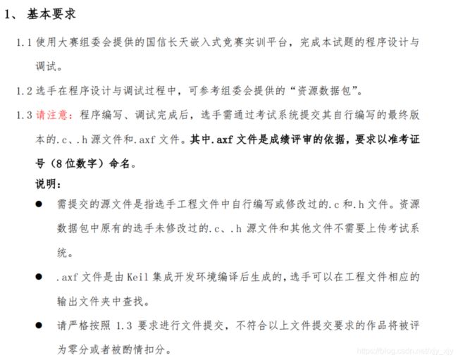
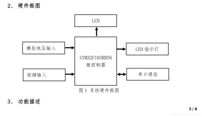
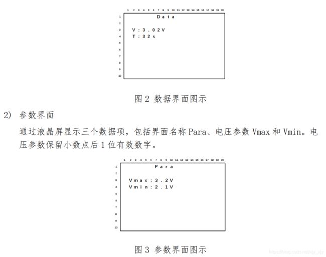
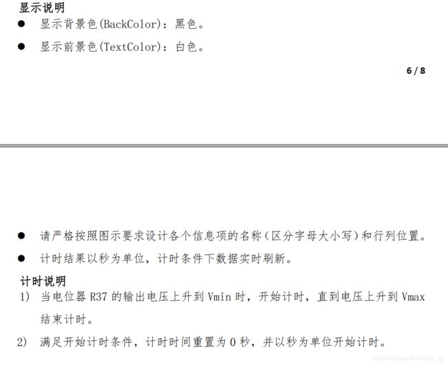
一、试题
二、需要用到的模块
1.LED
代码如下:led.c:
#include "led.h"

void led_init(void)
{

  GPIO_InitTypeDef GPIO_InitStructure;

  RCC_APB2PeriphClockCmd(RCC_APB2Periph_GPIOD | RCC_APB2Periph_GPIOC, ENABLE);

  /* Configure PD0 and PD2 in output pushpull mode */
  GPIO_InitStructure.GPIO_Pin = GPIO_Pin_2;
  GPIO_InitStructure.GPIO_Speed = GPIO_Speed_50MHz;
  GPIO_InitStructure.GPIO_Mode = GPIO_Mode_Out_PP;
  GPIO_Init(GPIOD, &GPIO_InitStructure);

   GPIO_InitStructure.GPIO_Pin = 0xff00;
   GPIO_Init(GPIOC, &GPIO_InitStructure);
   GPIOC->ODR |=0xff<<8;
   GPIOD->ODR |=1<<2;
   GPIOD->ODR &=~(1<<2);
}

void led_ctrl(u8 ledx,u8 status)   //控制led的亮灭,ledx取值范围:8-15
{

	if(status)
	{

		GPIOC->ODR &=~(1<<ledx);
   		GPIOD->ODR |=1<<2;
   		GPIOD->ODR &=~(1<<2);
	}
	else
	{

	  	GPIOC->ODR |=1<<ledx;
   		GPIOD->ODR |=1<<2;
   		GPIOD->ODR &=~(1<<2);
	}
}
led.h:
#ifndef LED_H
#define LED_H

#include "stm32f10x.h"

void led_init(void);
void led_ctrl(u8 ledx,u8 status);
#endif
2.按键
代码如下:key.c:
#include "key.h"

void key_init(void)
{

  GPIO_InitTypeDef GPIO_InitStructure;

  RCC_APB2PeriphClockCmd(RCC_APB2Periph_GPIOA | RCC_APB2Periph_GPIOB, ENABLE);

  /* Configure PD0 and PD2 in output pushpull mode */
  GPIO_InitStructure.GPIO_Pin = GPIO_Pin_0 | GPIO_Pin_8;
  GPIO_InitStructure.GPIO_Mode = GPIO_Mode_IN_FLOATING;
  GPIO_Init(GPIOA, &GPIO_InitStructure);

  GPIO_InitStructure.GPIO_Pin = GPIO_Pin_1 | GPIO_Pin_2;
  GPIO_Init(GPIOB, &GPIO_InitStructure);

}
key.h:
#include "key.h"

#ifndef KEY_H
#define KEY_H

#include "stm32f10x.h"

#define key1 GPIO_ReadInputDataBit(GPIOA,GPIO_Pin_0)   //读取按键的状态
#define key2 GPIO_ReadInputDataBit(GPIOA,GPIO_Pin_8)
#define key3 GPIO_ReadInputDataBit(GPIOB,GPIO_Pin_1)
#define key4 GPIO_ReadInputDataBit(GPIOB,GPIO_Pin_8)

void key_init(void);
#endif
3.ADC
代码如下:adc.c:
#include "adc.h"

void adc_init(void)
{

  ADC_InitTypeDef ADC_InitStructure;
  GPIO_InitTypeDef GPIO_InitStructure;
  RCC_ADCCLKConfig(RCC_PCLK2_Div6);
  /* Enable ADC1, ADC2 and GPIOC clock */
  RCC_APB2PeriphClockCmd(RCC_APB2Periph_ADC1 | RCC_APB2Periph_GPIOB, ENABLE);
  /* Configure PC.01, PC.02 and PC.04 (ADC Channel11, Channel12 and Channel14)
    as analog input ----------------------------------------------------------*/
  GPIO_InitStructure.GPIO_Pin = GPIO_Pin_0;
  GPIO_InitStructure.GPIO_Mode = GPIO_Mode_AIN;
  GPIO_Init(GPIOB, &GPIO_InitStructure);

  ADC_InitStructure.ADC_Mode = ADC_Mode_Independent;
  ADC_InitStructure.ADC_ScanConvMode = ENABLE;
  ADC_InitStructure.ADC_ContinuousConvMode = ENABLE;
  ADC_InitStructure.ADC_ExternalTrigConv = ADC_ExternalTrigConv_None;
  ADC_InitStructure.ADC_DataAlign = ADC_DataAlign_Right;
  ADC_InitStructure.ADC_NbrOfChannel = 1;
  ADC_Init(ADC1, &ADC_InitStructure);
  /* ADC2 regular channels configuration */
  ADC_RegularChannelConfig(ADC1, ADC_Channel_8, 1, ADC_SampleTime_239Cycles5);

  ADC_Cmd(ADC1, ENABLE);

  /* Enable ADC1 reset calibration register */
  ADC_ResetCalibration(ADC1);
  /* Check the end of ADC1 reset calibration register */
  while(ADC_GetResetCalibrationStatus(ADC1));

  /* Start ADC1 calibration */
  ADC_StartCalibration(ADC1);
  /* Check the end of ADC1 calibration */
  while(ADC_GetCalibrationStatus(ADC1));
}


u16 get_adc(void)     //简单的滤波,求平均值,获取12位的adc值
{

	int i;
	u16 adc_buff[10];
	ADC_SoftwareStartConvCmd(ADC1, ENABLE);
	for(i=0;i<10;i++)
	{

		 adc_buff[i]=ADC_GetConversionValue(ADC1);
	}
	for(i=1;i<10;i++)
	{

		adc_buff[0] += adc_buff[i];
	}
	ADC_SoftwareStartConvCmd(ADC1, DISABLE);
	return adc_buff[0]/10;


}
adc.h:
#ifndef ADC_H
#define ADC_H

#include "stm32f10x.h"

void adc_init(void);
u16 get_adc(void);

#endif
4.串口2
代码如下:usart2.c:
#include "usart.h"

u8 rx_flag=0;
void usart2_init(void)
{

  USART_InitTypeDef USART_InitStructure;
  GPIO_InitTypeDef GPIO_InitStructure;
  NVIC_InitTypeDef NVIC_InitStructure;

  RCC_APB2PeriphClockCmd(RCC_APB2Periph_GPIOA, ENABLE);
  RCC_APB1PeriphClockCmd(RCC_APB1Periph_USART2, ENABLE);
  /* Enable the USARTy Interrupt */
  NVIC_InitStructure.NVIC_IRQChannel = USART2_IRQn;
  NVIC_InitStructure.NVIC_IRQChannelSubPriority = 0;
  NVIC_InitStructure.NVIC_IRQChannelCmd = ENABLE;
  NVIC_Init(&NVIC_InitStructure);

  GPIO_InitStructure.GPIO_Pin = GPIO_Pin_3;
  GPIO_InitStructure.GPIO_Mode = GPIO_Mode_IN_FLOATING;
  GPIO_Init(GPIOA, &GPIO_InitStructure);

  USART_InitStructure.USART_BaudRate = 9600;
  USART_InitStructure.USART_WordLength = USART_WordLength_8b;
  USART_InitStructure.USART_StopBits = USART_StopBits_1;
  USART_InitStructure.USART_Parity = USART_Parity_No;
  USART_InitStructure.USART_HardwareFlowControl = USART_HardwareFlowControl_None;
  USART_InitStructure.USART_Mode = USART_Mode_Rx ;

  /* Configure USARTy */
  USART_Init(USART2, &USART_InitStructure);

  USART_ITConfig(USART2, USART_IT_RXNE, ENABLE);

  /* Enable the USARTy */
  USART_Cmd(USART2, ENABLE);
}
u8 usart_buff[7] ;  //不能太大,只能刚刚好7个大小,命令字符串的长度

u8 count=0;
u8 erro_flag=0;
void USART2_IRQHandler(void)
{

  if(USART_GetITStatus(USART2, USART_IT_RXNE) != RESET)
  {


    /* Read one byte from the receive data register */

   	 usart_buff[count]=USART_ReceiveData(USART2);
	 if(usart_buff[1]=='.' && usart_buff[3]==',' && usart_buff[5]=='.' && count==6 )
	 {

	 	rx_flag=1;
		USART_Cmd(USART2, DISABLE);

	 }
	 else
	 {

		count++;
		if(count>1 && usart_buff[1]!='.')				  //一发现接收的第二个不是'.',就清空数组,并告诉主循环错了,在主循环把在第二个后面发送的数据清空
		{

			u8 i;

			for(i=0;i<7;i++)
			{

				usart_buff[i]=0;
			}
			erro_flag=1;								 //格式错误标志,在主循环中需要用到


		}

		if(count>3 && usart_buff[3]!=',')			 //同上
		{

			u8 i;

			for(i=0;i<7;i++)
			{

				usart_buff[i]=0;
			}
			erro_flag=1;


		}

		if(count>5 && usart_buff[5]!='.')
		{

			u8 i;

			for(i=0;i<7;i++)
			{

				usart_buff[i]=0;
			}
			erro_flag=1;

		}
		if(count==7)									 //超数组下标
		{

			u8 i;
			count=0;
			for(i=0;i<7;i++)
			{

				usart_buff[i]=0;
			}
			erro_flag=1;
		}
	 }
  }
}
usart2.h:
#ifndef USART_H
#define USART_H

#include "stm32f10x.h"
extern u8 rx_flag;
extern u8 usart_buff[7];
extern u8 count;
extern u8 erro_flag;

void usart2_init(void);
#endif
5.RTC实时时钟
代码如下:rtc.c:
#include "rtc.h"
u8 TimeDisplay=0;
void rtc_init(void)
{

  NVIC_InitTypeDef NVIC_InitStructure;

  /* Configure one bit for preemption priority */
  NVIC_PriorityGroupConfig(NVIC_PriorityGroup_1);

  /* Enable the RTC Interrupt */
  NVIC_InitStructure.NVIC_IRQChannel = RTC_IRQn;
  NVIC_InitStructure.NVIC_IRQChannelPreemptionPriority = 0;
  NVIC_InitStructure.NVIC_IRQChannelSubPriority = 0;
  NVIC_InitStructure.NVIC_IRQChannelCmd = ENABLE;
  NVIC_Init(&NVIC_InitStructure);

  /* Enable PWR and BKP clocks */
  RCC_APB1PeriphClockCmd(RCC_APB1Periph_PWR | RCC_APB1Periph_BKP, ENABLE);

  /* Allow access to BKP Domain */
  PWR_BackupAccessCmd(ENABLE);

  /* Reset Backup Domain */
  BKP_DeInit();

  /* Enable the LSI OSC */
  RCC_LSICmd(ENABLE);
  /* Wait till LSI is ready */
  while (RCC_GetFlagStatus(RCC_FLAG_LSIRDY) == RESET)
  {
     }
  /* Select the RTC Clock Source */
  RCC_RTCCLKConfig(RCC_RTCCLKSource_LSI);

  /* Enable RTC Clock */
  RCC_RTCCLKCmd(ENABLE);

  /* Wait for RTC registers synchronization */
  RTC_WaitForSynchro();

  /* Wait until last write operation on RTC registers has finished */
  RTC_WaitForLastTask();

  /* Enable the RTC Second */
  RTC_ITConfig(RTC_IT_SEC, ENABLE);

  /* Wait until last write operation on RTC registers has finished */
  RTC_WaitForLastTask();

  /* Set RTC prescaler: set RTC period to 1sec */
  RTC_SetPrescaler(40000);

  /* Wait until last write operation on RTC registers has finished */
  RTC_WaitForLastTask();
}
void RTC_IRQHandler(void)   //每1S进入中断
{

  if (RTC_GetITStatus(RTC_IT_SEC) != RESET)
  {

    /* Clear the RTC Second interrupt */
    RTC_ClearITPendingBit(RTC_IT_SEC);


    /* Enable time update */
    TimeDisplay = 1;         //主函数死循环里的标志位,对定时值进行自加,达到计时的效果

    /* Wait until last write operation on RTC registers has finished */
    RTC_WaitForLastTask();

  }
}
rtc.h:
#ifndef RTC_H
#define RTC_H

#include "stm32f10x.h"
extern u8 TimeDisplay;
void rtc_init(void);

#endif
三、主函数逻辑设计
思路流程图:
Created with Raphaël 2.2.0 开始 按键扫描 adc值的获取 数据包格式正确? 数据包格式错误? 1s计时判断 界面显示 结束? yes
stm32f10x_it.c:
#include "stm32f10x_it.h"

extern u32 TimingDelay;
extern u8 key_flag;

void SysTick_Handler(void)
{

	static u8 key_num=0;
	TimingDelay--;
	key_num++;
	if(key_num==50)   //50ms定时标志,进行按键的扫描和adc值的获取
	{

		key_flag=1;
		key_num=0;
	}

}
main.c:
#include "stm32f10x.h"
#include "lcd.h"
#include "stdio.h"
#include "led.h"
#include "key.h"
#include "adc.h"
#include "usart.h"
#include "rtc.h"
u32 TimingDelay = 0;
u32 time=0;						 //定时值
float string_int(char  s);	    // 字符串转整形数,再以浮点型的数值返回
float num1=1,num2=2,num3=3,num4=4;		 //用来提取解析串口传输过来的数值
u8 key_flag=0;							 //定时扫描标志,50ms扫描一次按键状态
u8 key1_num=0;							 //按键1按下的计数标志,用于判断长按短按,每50ms加一
u8 key2_num=0;							 //按键2按下的计数标志,用于判断长按短按,每50ms加一
u8 key3_num=0;							 //按键3按下的计数标志,用于判断长按短按,每50ms加一
u8 min_flag;   //电压低于最小值,用于判断电压的变化是从低于最低值上升到比最低值高,1:是,定时值清0
u8 max_flag;   //电压超最大值,停止计时
u8 buff[20];   //用于进行数据的拷贝显示
u8 i;		   //for循环需要的变量
u8 key1_flag=0;	               //按键1按下的标志,用于区分显示的界面 1:参数界面  0:数据界面
float adc_val;		           //用于获取adc的12位数据值,然后进行电压数字转换
float max=3.0,min=1.0;		   //最大,最小电压 参数
float max_temp,min_temp;	   用于存储最大最小电压修改前的值

void Delay_Ms(u32 nTime);
void key_read(void);			//按键扫描
void lcd_show(void);			//界面的显示
int main(void)
{

	SysTick_Config(SystemCoreClock/1000);

	Delay_Ms(200);

	STM3210B_LCD_Init();
	LCD_Clear(Black);
	LCD_SetBackColor(Black);
	LCD_SetTextColor(White);
	led_init();
	key_init();
	adc_init();
	usart2_init();
	rtc_init();


	while(1)
	{

		if(key_flag)				  //0.05扫描,按键响应和电压刷新0.05秒
		{

			key_read();
			adc_val=get_adc();	      //这里只获取12位的adc值
			key_flag=0;
		}

		if(rx_flag )
		{

			max_temp=max;
			min_temp=min;
			count=0;
			num1=string_int(usart_buff[0]);
			num2=string_int(usart_buff[2]);
			num3=string_int(usart_buff[4]);
			num4=string_int(usart_buff[6]);				//获取数据

			max=num1+num2/10;						   // 转换成浮点型数据
		    min=num3+num4/10;
			if(max>3.3 || min>3.3 || max<min+1)		  //串口的数据不符合
			{

				max=max_temp;
				min=min_temp;							//把数据还原成修改前的数据
				led_ctrl(10,1);							//led3亮
			}
			else									   //数据正确了 灯灭
			{

				led_ctrl(10,0);
			}
			for(i=0;i<7;i++)
			{

				usart_buff[i]=0;
			}
			rx_flag=0;
			USART_Cmd(USART2, ENABLE);						 //处理完数据后重新开启串口


		}
		if(erro_flag )      //串口发送的数据有错
		{

			led_ctrl(10,1);				  //数据的格式错,led3亮
			erro_flag=0;
			for(i=0;i<7;i++)			 //再一次清空buff
			{

				usart_buff[i]=0;
			}
			count=0;				     //数组下标回到0
		}
		if(TimeDisplay)
		{

			if(adc_val/0xfff*3.3<max && adc_val/0xfff*3.3>min  && max_flag==0)		   //电压的变化在最大和最小之间,且数据还没超过最大,	定时数自加
			{

				time++;
				led_ctrl(8,1);															   //led1亮
			}
			if(adc_val/0xfff*3.3 > max)			 //数据超过最大值,定时停止,
			{

				led_ctrl(8,0);		  //关灯
				max_flag=1;
			}
			if(adc_val/0xfff*3.3 < min  )	//定时值小于min,记录起来min_flag=1;
			{

				if(max_flag==0)					   //如果这时数据的变化没有超过max,定时器还是会计时的
				{

					time++;
					led_ctrl(8,1);
				}


				min_flag=1;
			}
			if(adc_val/0xfff*3.3>min  &&   min_flag==1)		//数据从低于min变化到高于min,定时值清0
			{

				time=0;
				min_flag=0;
				max_flag=0;
			}

			TimeDisplay=0;
		}
		lcd_show();					   //界面显示


	}
}

//
void Delay_Ms(u32 nTime)
{

	TimingDelay = nTime;
	while(TimingDelay != 0);
}

void key_read(void)
{

	if(key1==0)						      //按键1
	{

		key1_num++;
		if(key1_num>20)				  //长按
		{

			led_ctrl(8,0);
		}
	}
	else
	{

		if(key1_num>1  &&  key1_num<10)			 //短按
		{

			key1_flag ^=1;
			if(key1_flag)			     //key1_flag=1:切换到参数界面,保存切换前的数据
			{

				max_temp=max;
				min_temp=min;
			}
			else
			{

				if(max<min+1)		    //判断数据是否合法
				{

					led_ctrl(9,1);		  //不合法进行还原数据和点亮led2
					max=max_temp;
					min=min_temp;
				}
				else						  //合法就熄灭灯
				{

					led_ctrl(9,0);
				}
			}
		}
		key1_num=0;
	}

	if(key2==0 && key1_flag)	     //key2按下,且目前是在参数设置界面才有效
	{

		key2_num++;
		if(key2_num>20)
		{


		}
	}
	else
	{

		if(key2_num>1  &&  key2_num<10)	   //短按
		{

		    max=max+0.1;		         //数据加0.1
			if(max>3.3)
			{

				max=0;
			}
		}
		key2_num=0;
	}

	if(key3==0 && key1_flag)		  //key3按下,且目前是在参数设置界面才有效
	{

		key3_num++;
		if(key3_num>20)			 //长按
		{

								 //目前不需要
		}
	}
	else
	{

		if(key3_num>1  &&  key3_num<10)		//短按
		{

			min=min+0.1;
			if(min>3.3)
			{

				min=0;
			}
		}
		key3_num=0;
	}
}

float string_int(char  s)
{

	float n;
	switch(s)
	{

		case '0': 	n=0;
					break;

		case '1':   n=1;
					break;

		case '2':   n=2;
					break;

		case '3':   n=3;
					break;

		case '4':   n=4;
					break;

		case '5':   n=5;
					break;

		case '6':   n=6;
					break;

		case '7':   n=7;
					break;

		case '8':   n=8;
					break;

		case '9':   n=9;
					break;

		default:break;

	}
	return n;
}

void lcd_show(void)
{

		if(key1_flag==0)
		{

			LCD_DisplayStringLine(Line0,"      Data");
	   		sprintf((char *)buff," V:%0.2fV            ",adc_val/0xfff*3.3);
			LCD_DisplayStringLine(Line2,buff);
			sprintf((char *)buff," T:%ds            ",time);
			LCD_DisplayStringLine(Line3,buff);

		}
		else
		{

			LCD_DisplayStringLine(Line0,"      Para");
			sprintf((char *)buff," Vmax:%0.1fV            ",max);
			LCD_DisplayStringLine(Line2,buff);
			sprintf((char *)buff," Vmin:%0.1fV            ",min);
			LCD_DisplayStringLine(Line3,buff);
		}
}
四、 总结
本试题的难点主要有:
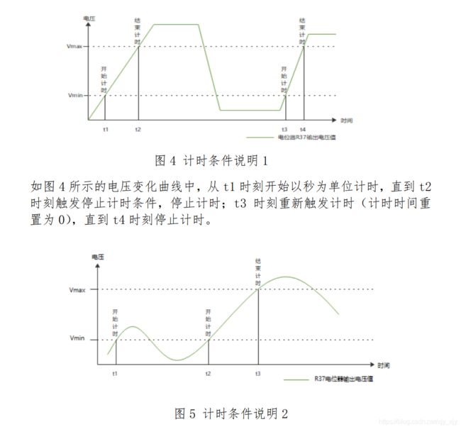
①电压变化曲线的理解
- 在最大值和最小值之间会进行计时。
- 大于最大值停止计时但不清0。
- 电压变化过程中在没有大于最大值的情况下,都会进行计时。
- 在电压从低于最低值上升到高于最低值,计时值要清0。
②串口数据包格式判断
- 使用串口调试助手发送数据,发送的字节数程序无不知道。
- 串口中断是接收1字节一次中断,用数组存放数据,数组大小为7。
- 判断数组[1]=’ . ’ ,数组[3]=’ , ‘,数组[5]=’ . ’ , 接收的数据达到7个也就是下标为6就到主循环进行数据分析,判断数据是否符合逻辑和满足0-3.3之间。
- 数据一旦不满足上面的条件就把数组清空。
③字符串转成浮点型数据
- 串口接收到的数据是字符型的,以ASCII存储。
- 用switch进行每个数字字符的判断,转换为float。
- 也可以用该数字字符减去’0’, 得到该数值,转换成float , 如:’ 9 ’ - ’ 0 '=9。
