HCNA笔记
@城建黑师兄
HCNA 笔记
在空闲的时间里去做的笔记
eNSP及VRP基础操作
1.1 熟悉VRP基本操作
最初配置
Sysname  //名字修改名字
clock datetime 00:00:00 2018-07-28  //设置路由时钟
clock timezone BJ add 08:00:00  //设置时区
header login information“HELLO” // 设置标题登录时的信息
header shell information“hello da chen” //设置标题登录后的信息
display version  //查看路由版本信息
display current-configuration //查看路由当前配置
display int g0/0/0(端口号可变)//查看端口信息


最终配置
display current-configuration
[V200R003C00]
#
 sysname R1
 header shell information "Welcome to Huawei certification lab"
 header login information "hello"
#
 clock timezone BJ add 08:00:00
 clock daylight-saving-time Day Light Saving Time repeating 12:32 9-1 12:32 11-23 00:00 2005 2005
#
interface GigabitEthernet0/0/0
 ip address 10.1.1.1 255.255.255.0
#
Return
1.2熟悉常用的IP相关命令
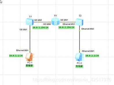
本实验模拟简单的企业网络场景,某公司购买了新的路由器和交换机。交换机S
连接客服部PC-1,S2连接市场部PC-2,路由器R1连接S1和S2两台交换机。网络管
理员需要首先熟悉设备的使用,包括基础的P配置和查看命令。
最终配置
display current-configuration
[V200R003C00]
#
 sysname R1
#
interface GigabitEthernet0/0/0
 ip address 10.0.1.254 255.255.255.0
#
interface GigabitEthernet0/0/1
 ip address 10.0.2.254 255.255.255.0
#
return
1.3 配置通过Telnet登录系统
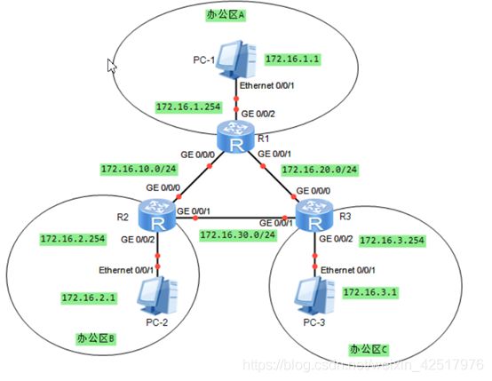
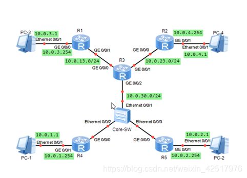
实验内容
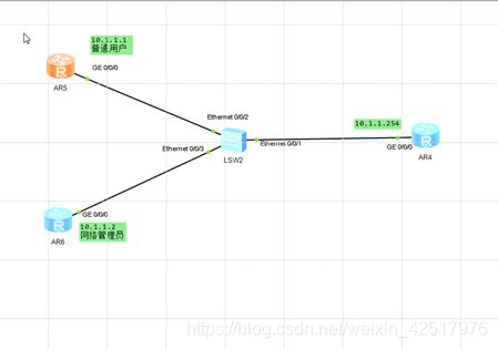
本实验模拟公司网络场景。路由器R是公司机房的一台设备,公司员工的办公区
与机房不在同一个楼层,路由器R2和R3模拟员工主机,通过交换机S1与机房设备相
连。为了方便用户的管理,现需要在路由器R1上配置 Telnet使用户能在办公区远程管
理机房设备。为了提高安全性, Telnet需要使用密码认证,只有网络管理员能对设备进行配置和管理,普通用户仅能监控设备
最初配置
Vty视图的
User-interface vty 0 4  //(进入vty模式)
Authentication-mode password  //(验证方式为密码的形式)
Set authentication password cipher Huawei  //(加密的密码,明文密码为 simple)
User privilege level 1  // (级别为0为参观级别,1监控级别, 2为配置级别,3为管理级别)
AAA视图的
Aaa   //(进入aaa 模式)
Local-user admin password cipher huawei privilege level 3  //(命名用户名,配密码,给级别)
Local-user admin service-type Telnet   //(用户接入类型为Telnet)
User-interface vty 0 4  //(进入vty模式改验证模式)
Authentication-mode aaa  //(改为aaa验证)

最终配置
display current-configuration
#
sysname R1
#
interface GigabitEthernet0/0/0
 ip address 10.1.1.254 255.255.255.0
#
Return

display current-configuration
#
sysname R2
#
interface Ethernet0/0/0
 ip address 10.1.1.1 255.255.255.0
#
return

display current-configuration
#
sysname R3
#
interface Ethernet0/0/0
 ip address 10.1.1.2 255.255.255.0
#
return
###1.4 配置通过STelnet登录系统
实验内容
使用路由器R1模拟PC,作为SSH的 Client;路由器R2作为SSH的 Server,模拟
远程用户端R1通过SSH协议远程登录到路由器R2上进行各种配置。本实验将通过Password认证方式来实现

最初配置
R2:
Rsa local-key-pair create  //(生成本地主机秘钥对)
User-interface vty 0 4  //(进入vty模式)
Authentication-mode aaa  //(验证方式为aaa)
Protocol inbound ssh  //(仅支持ssh协议)
Aaa  //(进入aaa 模式)
Local-user huawei password cipher Huawei //(命名用户、给密码)
Local-user huawei service-type ssh  //(配置用户的接入类型为ssh)
Ssh user huawei authentication-type password  //(创建ssh 用户的验证方式为password)
Stelnet server enable  //(开启加密登录服务)
Display rsa local-type-pair public  // (查看本地秘钥中的信息)
Display ssh user-information huawei  //(查看ssh 用户信息/全局配置)display ssh server status
R1
Ssh client first-time enable  //(第一次开启ssh登录服务)
Stelnet IP地址
最终配置
display current-configuration
sysname R1
#
 set cpu-usage threshold 80 restore 75
#
 rsa peer-public-key 10.1.1.254
  public-key-code begin
   3047
     0240
       B910F7D8 EF50B04E CCF8692A 4F1B3FB3 202C3E66 B6D2C7EB FDBF0909 ED160F5E
       76B5D916 CBB29432 F9044E04 8434B0AB E8FAB968 1672958B F732F788 0DA94F85
     0203
       010001
  public-key-code end
 peer-public-key end
#
interface GigabitEthernet0/0/0
 ip address 10.1.1.1 255.255.255.0
#
 ssh client 10.1.1.254 assign rsa-key 10.1.1.254
 ssh client first-time enable

display current-configuration
sysname R2
#
aaa
 authentication-scheme default
 authorization-scheme default
 accounting-scheme default
 domain default
 domain default_admin
 local-user admin password cipher %$%$K8m.Nt84DZ}e#<0`8bmE3Uw}%$%$
 local-user admin service-type http
 local-user huawei1 password cipher %$%$cRb~BL,]5D(!v-QiMgd$:RxE%$%$
 local-user huawei1 privilege level 3
 local-user huawei1 service-type ssh
#
interface GigabitEthernet0/0/0
 ip address 10.1.1.254 255.255.255.0
#
stelnet server enable
#
user-interface vty 0 4
 auth
 protocol inbound ssh
1.5 配置通过FTP进行文件操作
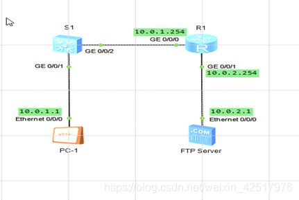
实验内容
本实验模拟企业网络,PC1为FP用户端设备,需要访 FTP Server,从服务器上下载或上传文件。出于安全角度考虑,为防止服务器被病毒文件感染,不允许用户端直接上传文件到 Server。网络管理员在R1上设置了限制,使员工不能上传文件到 Server,但是可以从Server下载文件。R1也需要作为用户端从 Server下载更新文件,同时配置R1作为FTP服务器,员工可上传文件到R1上,经过管理员的检测后由R1再上传到 FTP Server
最初配置
在电脑里建一个名为“FTP-Huawei”的文件夹,子文件夹为“config”文件为“test.txt”
在FTP服务器里设置刚才建的文件夹为FTP的文件夹,设置完,启动ftp服务


R1
ftp 10.0.2.1 (R1登录到ftp 服务器)——要给用户名和密码(随便你给)

Ls 查看 ftp 服务器有没有config 文件夹
Cd config  //进入文件夹
Dir  //查看config文件夹属性
Get test.txt  //(从ftp服务器下载到路由器上)
Put test.txt new.txt  //(从路由器上传到FTP服务器上,并且改了名字)
ftp server enable  //(配置路由器为ftp 服务器)
Aaa  //(进入aaa模式)
Local-user ftp password cipher huawei privilege level 15  //(起名字,配密码,给级别)
Local-user ftp ftp-directory flash  //(设置ftp 可访问的目录)
Local-user ftp server-type ftp  //(用户服务类型为ftp)


PC1
服务地址为R1 0/0 端口地址,用户名为ftp,密码为huawei,弄好点登陆,就可以把各盘里点两点小于1M的文件上传到路由上了(1M是对模拟器来说的),再由路由器上传到服务器上

最终配置
display current-configuration
[V200R003C00]
#
sysname R1
ftp server enable
#
aaa
local-user ftp password cipher %$%$%/xlTEcUeFU_="WB+iPI_n:M%$%$
local-user ftp ftp-directory flash:
local-user ftp service-type ftp
#
interface GigabitEthernet0/0/0
ip address 10.0.1.254 255.255.255.0
#
interface GigabitEthernet0/0/1
ip address 10.0.2.254 255.255.255.0
#
Return
静态路由
2.1 静态路由及默认路由基本配置
在由3台路由器组成的简单网络中,R1与R3各自连接着一台主机,现在要求能够实现主机PC1与PC2之间的正常通信。本实验通过配置基本的静态路由和默
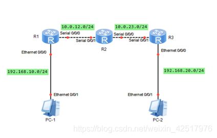
初始化
R1:
sys
sysname R1
int e0/0/0
ip add 192.168.10.254 24
int s0/0/0
ip add 10.0.12.1 24
q

R2:
sys
sysname R2
int s0/0/1
ip add 10.0.12.2 24
int s0/0/0
ip add 10.0.23.2 24
q

R3:
sys
sysname R3
int s0/0/1
ip add 10.0.23.3 24
int e0/0/0
ip add 192.168.20.254 24
q

实现PC1和PC2之间的通信
R1
ip route-static 192.168.20.0 255.255.255.0 10.0.12.2
ip route-static 10.0.23.0 255.255.255.0 10.0.12.2           //外人的

R2
ip route-static 192.168.10.0 255.255.255.0 10.0.12.1
ip route-static 192.168.20.0 255.255.255.0 10.0.23.3

R3
ip route-static 192.168.10.0 24 10.0.23.2
ip route-static 10.0.12.0 24 10.0.23.2

最终配置
display current-configuration
#
sysname R1
#
interface Ethernet0/0/0
 ip address 192.168.10.1 255.255.255.0
#
interface Serial0/0/0
 link-protocol ppp
 ip address 10.0.12.1 255.255.255.0
#
ip route-static 0.0.0.0 0.0.0.0 10.0.12.2
#
Return

display current-configuration
#
sysname R2
#
interface Serial0/0/0
 link-protocol ppp
 ip address 10.0.23.2 255.255.255.0
#
interface Serial0/0/1
 link-protocol ppp
 ip address 10.0.12.2 255.255.255.0
#
ip route-static 192.168.10.0 255.255.255.0 Serial0/0/1
ip route-static 192.168.20.0 255.255.255.0 10.0.23.3
#
Return

display current-configuration
#
sysname R3
#
interface Ethernet0/0/0
 ip address 192.168.20.3 255.255.255.0
#
interface Serial0/0/1
 link-protocol ppp
 ip address 10.0.23.3 255.255.255.0
#
ip route-static 0.0.0.0 0.0.0.0 Serial0/0/1
#
Return
2.2 浮动静态路由及负载均衡
R2为某公司总部,R1与R3是两个分部,主机PC1与PC2所在的分别模拟两个分部中的办公网络。现需总部与各个分部,分部与分部之间都能够通信,且分部之间在通信时,之间直连链路为主用链路,通过总部的主用链路为备用链路。本实验使用浮动静态路由实现要求,并且根据需求来实现负载均衡来优化网络。

初始化
R1:
sys
sysname R1
int g0/0/0
ip add 192.168.10.1 24
int s1/0/0
ip add 10.0.12.1 24
int s1/0/1
ip add 10.0.13.1 24
q
ip route-static 192.168.20.0 255.255.255.0 10.0.13.3

R2:
sys
sysname R2
int s1/0/0
ip add 10.0.12.2 24
int s1/0/1
ip add 10.0.23.2 24
q
ip route-static 192.168.10.0 24 10.0.12.1
ip route-static 192.168.20.0 24 10.0.23.3

R3:
sys
sysname R3
int g0/0/0
ip add 192.168.20.1 24
int s1/0/0
ip add 10.0.23.3 24
int s1/0/1
ip add 10.0.13.3 24
q
ip route-static 192.168.10.0 24 10.0.13.1

配置浮动静态路由实现路由备份
R1:
ip route-static 192.168.20.0 24 10.0.12.2 preference 100  //(默认60,优先值越高越优低)

R3:
ip route-static 192.168.10.0 24 10.0.23.2 preference 100

查看路由命令dis ip routing-table无法查看到备份路由
要使用命令dis ip routing-table protocol static命令仅查看静态路由可看到

配置负载均衡(2条路由的优先级一样即可)(恢复R1和R3的浮动静态路由的优先级
)
R1:
ip route-static 192.168.20.0 24 10.0.12.2

R3:
ip route-static 192.168.10.0 24 10.0.23.2
最终配置
display current-configuration
#
sysname R1
#
interface GigabitEthernet0/0/0
 ip address 192.168.10.1 255.255.255.0
#
interface Serial1/0/0
 link-protocol ppp
 ip address 10.1.12.1 255.255.255.0
#
interface Serial1/0/1
 link-protocol ppp
 ip address 10.1.13.1 255.255.255.0
#
ip route-static 192.168.20.0 255.255.255.0 10.1.13.3
ip route-static 192.168.20.0 255.255.255.0 10.1.12.2
#
Return

display current-configuration
#
sysname R2
#
interface Serial1/0/0
 link-protocol ppp
 ip address 10.1.12.2 255.255.255.0
#
interface Serial1/0/1
 link-protocol ppp
 ip address 10.1.23.2 255.255.255.0
#
ip route-static 192.168.10.0 255.255.255.0 10.1.12.1
ip route-static 192.168.20.0 255.255.255.0 10.1.23.3
#
Return

display current-configuration
#
sysname R3
#
interface GigabitEthernet0/0/0
 ip address 192.168.20.1 255.255.255.0
#
interface Serial1/0/0
 link-protocol ppp
 ip address 10.1.23.3 255.255.255.0
#
interface Serial1/0/1
 link-protocol ppp
 ip address 10.1.13.3 255.255.255.0
#
ip route-static 192.168.10.0 255.255.255.0 10.1.13.1
ip route-static 192.168.10.0 255.255.255.0 10.1.23.2
#
Return
RIP
3.1 RIP路由协议基本配置


初始化:
R1:
sys
sysname R1
int e0/0/0
ip add 10.0.12.1 24
int loopback 0
ip add 10.0.1.1 24
q

R2:
sys
sysname R2
int e0/0/0
ip add 10.0.12.2 24
int loopback 0
ip add 10.0.2.2 24
q

使用RIPv1搭建网络
R1,R2:
rip
network 10.0.0.0

dis ip routing-table

<>debugging rip 1
dis debugging
terminal debugging
terminal monitor debug

undo debugging rip 1
或undo debugging all

debugging rip 1 event

使用RIPv2搭建网络

最终配置
display current-configuration
#
sysname R1
#
interface Ethernet0/0/0
 ip address 10.0.12.1 255.255.255.0
#
interface LoopBack0
 ip address 10.0.1.1 255.255.255.0
#
rip 1
 version 2
 network 10.0.0.0
#
return

display current-configuration
#
sysname R2
#
interface Ethernet0/0/0
 ip address 10.0.12.2 255.255.255.0
#
interface LoopBack0
 ip address 10.0.2.2 255.255.255.0
#
rip 1
 version 2
 network 10.0.0.0
#
return
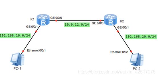
3.2 配置RIPv2的认证

初始化:
R1:
sys
sysname R1
int g0/0/0
ip add 192.168.10.1 24
int g0/0/1
ip add 10.0.12.1 24
q
R2:
sys
sysname R2
int g0/0/0
ip add 192.168.20.1 24
int g0/0/1
ip add 10.0.12.2 24
q
R3:
sys
sysname R3
int g0/0/0
ip add 10.0.12.3 24
int loopback 0
ip add 192.168.10.1 24
int loopback 1
ip add 192.168.20.1 24
q
搭建RIP网络
R1:
rip
version 2
network 192.168.10.0
network 10.0.0.0
q
R2:
rip
version 2
network 192.168.20.0
network 10.0.0.0
q
dis ip routing-table
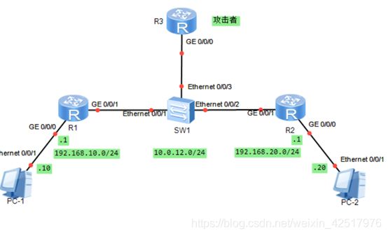
模拟R3网络攻击
R3:
rip
version 2
network 10.0.0.0
dis ip routing-table
rip
version 2
network 192.168.10.0
network 192.168.20.0
q
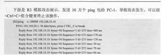
发送大量的数据包进行攻击(占用带宽,降低网速)
配置RIPv2简单验证
R1:
int g0/0/1
rip authentication-mode simple huawei
q

R2:
int g0/0/1
rip authentication-mode simple huawei
q

配置RIPv2 MD5密文验证
R1:
int g0/0/1
undo rip authentication-mode  // 去掉简单认证功能
rip authentication-mode md5 usual Huawei  //开启MD5模式
q

R2:
int g0/0/1
undo rip authentication-mode   去掉简单认证功能

rip authentication-mode md5 usual huawei
q

使用如下命令清除R3在密码错误之前从R2学到的路由信息
 reset ip routing-table statistics protocol rip
最终配置
display current-configuration
#
sysname R1
#
interface GigabitEthernet0/0/0
ip address 192.168.10.1 255.255.255.0
#
interface GigabitEthernet0/0/1
link-protocolppp
ip address 10.0.12.1 255.255.255.0
rip authentication-mode md5 nonstandard $GOOD_=eh*)f8\~B3e~&Z5%# 1
#
rip 1
version 2
network 192.168.10.0
network 10.0.0.0
#
return

display current-configuration
#
sysname R2
#
interface GigabitEthernet0/0/0
ip address 192.168.20.1 255.255.255.0
#
interface GigabitEthernet0/0/1
link-protocolppp
ip address 10.0.12.2 255.255.255.0
rip authentication-mode md5 nonstandard &-nhYkNR4BC,%TLlYj-OAF@#
#
rip 1
version 2
network 192.168.20.0
network 10.0.0.0
#
return

display current-configuration
#
sysname R3
#
Interface loopback0
ip address 192.168.10.10 255.255.255.0
#
Interface loopback1
ip address 192.168.20.20 255.255.255.0
#
interface GigabitEthernet0/0/1
link-protocolppp
ip address 10.0.12.1 255.255.255.0
rip authentication-mode md5 nonstandard $GOOD_=eh*)f8\~B3e~&Z5%# 1
#
rip 1
version 2
network 192.168.10.0
network 192.168.20.0
network 10.0.0.0
#
Return
3.3 RIP路由协议的汇总

初始化:
R1:
sys
sysname R1
int s1/0/0
ip add 192.168.12.1 24
q

R2:
sys
sysname R2
int s1/0/1
ip add 192.168.12.2 24
int s1/0/0
ip add 192.168.23.2 24
q

R3:
sys
sysname R3
int s1/0/1
ip add 192.168.23.3 24
int loopback 0
ip add 3.3.0.3 24
int loopback 1
ip add 3.3.1.3 24
int loopback 2
ip add 3.3.2.3 24
int loopback 3
ip add 3.3.3.3 24
q

配置RIPv1
R1:
rip 1
network 192.168.12.0

R2:
rip 1
network 192.168.12.0
network 192.168.23.0

R3:
rip 1
network 192.168.23.0
network 3.0.0.0

dis default-parameter rip

配置RIPv2自动汇总
R1,R2,R3
rip 1
version 2

rip 1
summary always  // 使自动汇总生效
或
int s1/0/1
undo rip split-horizon
q

配置RIPv2手动汇总
R3:
int s1/0/1
rip summary-address 3.3.0.0 255.255.252.0
q


在路由出接口上配置汇总路由
int g0/0/0
rip summary-address 172.16.0.0 255.255.0.0
最终配置
display current-configuration
#
sysname R1
#
interface Serial0/0/0
 link-protocol ppp
 ip address 192.168.12.1 255.255.255.0
#
rip 1
 version 2
 network 192.168.12.0
#
return

display current-configuration
#
sysname R2
#
interface Serial0/0/0
 link-protocol ppp
 ip address 192.168.23.2 255.255.255.0
#
interface Serial0/0/1
 link-protocol ppp
 ip address 192.168.12.2 255.255.255.0
#
rip 1
 version 2
 network 192.168.12.0
 network 192.168.23.0
#
return

display current-configuration
#
sysname R3
#
interface Serial0/0/1
 link-protocol ppp
 ip address 192.168.23.3 255.255.255.0
 rip summary-address 3.3.0.0 255.255.252.0
#
interface LoopBack0
 ip address 3.3.0.3 255.255.255.0
#
interface LoopBack1
 ip address 3.3.1.3 255.255.255.0
#
interface LoopBack2
 ip address 3.3.2.3 255.255.255.0
#
interface LoopBack3
 ip address 3.3.3.3 255.255.255.0
#
rip 1
 undo summary
 version 2
 network 192.168.23.0
 network 3.0.0.0
#
return
3.4 配置RIP的版本兼容、定时器及协议优先级
初始化:
R1:
sys
sysname R1
int g0/0/1
ip add 192.168.10.1 24
int g0/0/0
ip add 10.0.12.1 24
q
rip 1
network 192.168.10.0
network 10.0.0.0
q

R2:
sys
sysname R2
int g0/0/1
ip add 192.168.20.1 24
int g0/0/0
ip add 10.0.12.2 24
q
rip 1
version 2
network 192.168.20.0
network 10.0.0.0
q

R1:
int g0/0/0
rip version 2 broadcast/multicast   // 开启R1发送V2报文

int g0/0/0
undo rip output   //停止发送路由更新

R2
dis ip routing-table  //更新数据库
dis rip 1 database

rip
preference 90    //优先值越小,代表优先级越高

rip
timers rip 20 120 60  //报文更新时间为20秒,超时时间为120秒,垃圾收集60秒。
q
dis rip


最终配置
display current-configuration
#
sysname R1
#
interface GigabitEthernet0/0/0
 ip address 10.0.12.1 255.255.255.0
#
interface GigabitEthernet0/0/1
 ip address 192.168.10.1 255.255.255.0
#
rip 1
 version 2
 network 10.0.0.0
 network 192.168.10.0
preference 90
 timers rip 20 120 60
#
return

display current-configuration
#
sysname R2
#
interface GigabitEthernet0/0/0
 ip address 10.0.12.2 255.255.255.0
#
interface GigabitEthernet0/0/1
 ip address 192.168.20.1 255.255.255.0
#
rip 1
 version 2
 network 10.0.0.0
 network 192.168.20.0
#
return
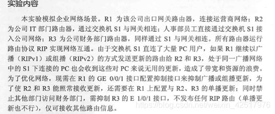
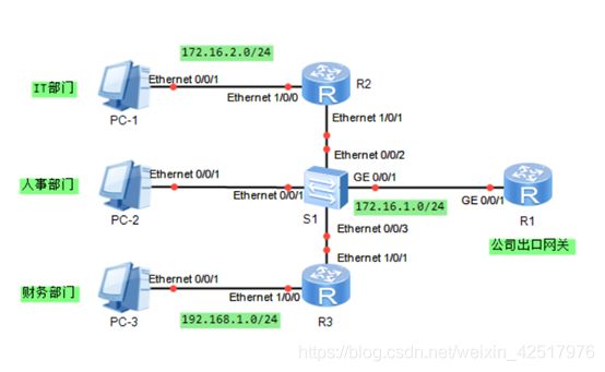
3.5 配置RIP抑制接口及单播更新
初始化:
R1:
sys
sysname R1
int g0/0/1
ip add 172.16.1.254 24
q
rip
network 172.16.0.0
q

R2:
sys
sysname R2
int e1/0/1
ip add 172.16.1.100 24
int e1/0/0
ip add 172.16.2.254 24
q
rip
network 172.16.0.0
q

R3:
sys
sysname R3
int e1/0/1
ip add 172.16.1.200 24
int e1/0/0
ip add 192.168.1.254 24
q

配置RIP抑制接口
R1:
rip
silent-int g0/0/1  //抑制接口不接受不发生报文(不更新报文),有效的控制环路问题,但是不能访问内网和外网

R2:
rip
silent-int e1/0/1
silent-int e1/0/0

R3:
rip
silent-int e1/0/1
silent-int e1/0/0

dis rip

配置RIP单播更新
R1:
rip
peer 172.16.1.100   //配置邻居路由
peer 172.16.1.200
q

R2:
rip
peer 172.16.1.254
peer 172.16.1.200
q

R3:
rip
peer 172.16.1.254
peer 172.16.1.100
q


法二:
rip 1
undo silent-int g0/0/1  //去掉之前的功能
undo peer 172.16.1.100
undo peer 172.16.1.200
int g0/0/1  //进入配置接口
undo rip output  //路由信息不更新出去,别人访问不了
peer 172.16.1.100  //为了能访问这个地址
peer 172.16.1.200
peer 172.16.1.254  //为了能访问外网

最终配置
display current-configuration
#
sysname R1
#
interface GigabitEthernet0/0/1
 ip address 172.16.1.254 255.255.255.0
#
rip 1
 peer 172.16.1.100
 peer 172.16.1.200
 network 172.16.0.0
 silent-interface GigabitEthernet0/0/1
#
Return

display current-configuration
#
sysname R2
#
interface Ethernet1/0/1
 ip address 172.16.1.100 255.255.255.0
#
interface Ethernet1/0/0
 ip address 172.16.2.254 255.255.255.0
#
rip 1
 peer 172.16.1.254
 peer 172.16.1.200
 network 172.16.0.0
 silent-interface Ethernet1/0/0
 silent-interface Ethernet1/0/1
#
Return

display current-configuration
#
sysname R3
#
interface Ethernet1/0/1
 ip address 172.16.1.200 255.255.255.0
 undo rip output
#
interface Ethernet1/0/0
 ip address 192.168.1.254 255.255.255.0
#
rip 1
 peer 172.16.1.254
 network 172.16.0.0
 network 192.168.1.0
#
return
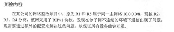
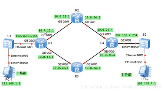
3.6 RIP与不连续子网

初始化:
R1:
sys
sysname R1
int e1/0/0
ip add  10.0.12.1 24
q
rip
network 10.0.0.0
q

R2:
sys
sysname R2
int e1/0/0
ip add 10.0.12.2 24
int s2/0/0
ip add 192.168.23.2 24
q
rip
network 10.0.0.0
network 192.168.23.0
q

R3:
sys
sysname R3
int s1/0/0
ip add  192.168.23.3 24
int s1/0/1
ip add  192.168.34.3 24
q
rip
network 192.168.23.0
network 192.168.34.0
q

R4:
sys
sysname R4
int s2/0/1
ip add  192.168.34.4 24
int e1/0/0
ip add  10.0.45.4 24
q
rip
network 192.168.34.0
network 10.0.0.0
q

R5:
sys
sysname R5
int e1/0/0
ip add 10.0.45.5 24
q
rip
network 10.0.0.0
q

[R1]ping 10.0.12.2
[R1]dis ip routing-table 或
[R1]dis ip routing-table protocol rip
[R2]dis ip routing-table
[R3]dis ip routing-table

[R3]ping 10.0.45.5
[R3]ping 10.0.12.1

RIPv1中解决不连续子网问题
R2:
int s2/0/0
ip add 10.0.23.2 24 sub
q

R3:
int s1/0/0
ip add 10.0.23.3 24 sub
int s1/0/1
ip add 10.0.34.3 24 sub
q
rip
network 10.0.0.0
q

R4:
int s2/0/1
ip add 10.0.34.4 24 sub
q

[R1][R2][R3]dis ip routing-table

RIPv2中解决不连续子网问题   直接关掉自动汇总
R1:
rip
version 2
undo summary
q

R2:
int s2/0/0
undo ip add 10.0.23.2 24 sub
rip
version 2
undo summary
q

R3:
int s1/0/0
undo ip add 10.0.23.3 24 sub
int s1/0/1
undo ip add 10.0.34.3 24 sub
rip
version 2
undo summary
q

R4:
int s2/0/1
undo ip add 10.0.34.4 24 sub
rip
version 2
undo summary
q

R1-5
dis ip routing-table

[R1]ping 10.0.45.5
最终配置
display current-configuration
#
interface Ethernet0/0/0
 ip address 10.0.12.1 255.255.255.0
#
rip 1
 undo summary
 version 2
 network 10.0.0.0
#

 display current-configuration
#
sysname R2
#
interface Ethernet0/0/0
 ip address 10.0.12.2 255.255.255.0
#
interface Serial0/0/0
 link-protocol ppp
 ip address 192.168.23.2 255.255.255.0
#
rip 1
 undo summary
 version 2
 network 10.0.0.0
 network 192.168.23.0
#

display current-configuration
#
sysname R3
#
interface Serial0/0/0
 link-protocol ppp
 ip address 192.168.23.3 255.255.255.0
#
interface Serial0/0/1
 link-protocol ppp
 ip address 192.168.34.3 255.255.255.0
#
rip 1
 undo summary
 version 2
 network 192.168.23.0
 network 192.168.34.0
#

display current-configuration
#
sysname R4
interface Ethernet0/0/0
 ip address 10.0.45.4 255.255.255.0
interface Serial0/0/1
 link-protocol ppp
 ip address 192.168.34.4 255.255.255.0
#
rip 1
 undo summary
 version 2
 network 192.168.34.0
 network 10.0.0.0

display current-configuration
#
sysname R5
#
interface Ethernet0/0/0
 ip address 10.0.45.5 255.255.255.0
#
rip 1
 undo summary
 version 2
 network 10.0.0.0
#
3.7 RIP的水平分割及触发更新


初始化:
R1:
sys
sysname R1
int g0/0/0
ip add 172.16.1.1 24
int g0/0/2
ip add 172.16.2.1 24
q
rip
version 2
network 172.16.0.0
q

R2:
sys
sysname R2
int g0/0/1
ip add 172.16.2.2 24
int e1/0/0
ip add 192.168.2.254 24
q
rip
version 2
network 172.16.0.0
network 192.168.2.0
q

R3:
sys
sysname R3
int g0/0/1
ip add 172.16.1.2 24
int e1/0/0
ip add 192.168.1.254 24
q
rip
version 2
network 172.16.0.0
network 192.168.1.0
q

[R1]dis ip routing-table


验证触发更新:

180s //老化计时器过后
R2: dis ip routing-table

验证水平分割:
debugging rip 1 send g0/0/1  //进入接口测试
terminal monitor
terminal debugging

undo debugging all  //关闭测试
sys
int g0/0/1
undo rip split-horizon  //关闭水平分割
q

R1:
sys
int g0/0/2
undo rip split-horizon
q

debugging rip 1 send g0/0/1
terminal monitor
terminal debugging

验证毒性逆转
undo debugging all
sys
int g0/0/1
rip split-horizon  //开启水平分割
q
q
debugging rip 1 send g0/0/1
terminal monitor
terminal debugging

undo debugging all
sys
int g0/0/1
rip poision-reverse  //开启毒性逆转
q
q
debugging rip 1 send g0/0/1
terminal monitor
terminal debugging


最终配置
display current-configuration
#
sysname R1
#
interface GigabitEthernet0/0/0
 ip address 172.16.1.1 255.255.255.0
#
interface GigabitEthernet0/0/2
 ip address 172.16.2.1 255.255.255.0
 undo rip split-horizon
#
rip 1
 version 2
 network 172.16.0.0
#
Return

display current-configuration
#
sysname R2
#
interface Ethernet1/0/0
 ip address 192.168.2.254 255.255.255.0
#
interface GigabitEthernet0/0/1
 ip address 172.16.2.2 255.255.255.0
 rip poison-reverse
#
rip 1
 version 2
 network 192.168.2.0
 network 172.16.0.0
#
Return

display current-configuration
#
sysname R3
#
interface Ethernet1/0/0
 ip address 192.168.1.254 255.255.255.0
#
interface GigabitEthernet0/0/1
 ip address 172.16.1.2 255.255.255.0
#
rip 1
 version 2
 network 172.16.0.0
 network 192.168.1.0
#
return
3.8 配置RIP路由附加度量值

初始化:
R1:
sys
sysname R1
int g0/0/2
ip add 192.168.1.254 24
int g0/0/0
ip add 10.0.12.1 24
int g0/0/1
ip add 10.0.13.1 24
q
rip
version 2
network 192.168.1.0
network 10.0.0.0
q

R2:
sys
sysname R2
int g0/0/0
ip add 10.0.12.2 24
int g0/0/1
ip add 10.0.24.2 24
q
rip
version 2
network 10.0.0.0
q

R3:
sys
sysname R3
int g0/0/0
ip add 10.0.34.3 24
int g0/0/1
ip add 10.0.13.3 24
q
rip
version 2
network 10.0.0.0
q

R4:
sys
sysname R4
int g0/0/1
ip add 10.0.24.4 24
int g0/0/0
ip add 10.0.34.4 24
int g0/0/2
ip add 192.168.2.254 24
q
rip
version 2
network 192.168.2.0
network 10.0.0.0
q

[R1]dis ip routing-table protocol rip

R1:
int g0/0/1
rip metricin 2
q
dis ip routing-table protocol rip

dis rip 1 database
配置RIP Metricin 设置R1在接收R3发送来的路由条目增加度量值2,这样R3发给R1的路由条目比R2 发给R1的还大,所以选择R2路线(别人告诉我这条路不好走,他要求我要换路走)

配置RIP Metricout
R2:
int g0/0/1
rip metricout 2
q

R4:
dis ip routing-table protocol rip
设置R2在向R4发送路由条目是增加度量值2,这样R4接收到来着R2的度量值大于R3的,所以选择R3路线(自己告诉别这条路不好走,强烈要求别人换路吧)
最终配置
display current-configuration
#
interface GigabitEthernet0/0/0
ip address 20.1.1.1 255.255.255.0
#
interface GigabitEthernet0/0/1
ip address 20.2.2.1 255.255.255.0
rip metricin 2
#
interface GigabitEthernet0/0/2
ip address 10.1.1.254 255.255.255.0
#
rip 1
undo summary
version 2
network 10.0.0.0
network 20.0.0.0
#
Return

display current-configuration
sysname r2
#
interface GigabitEthernet0/0/0
ip address 20.1.1.2 255.255.255.0
#
interface GigabitEthernet0/0/1
ip address 30.1.1.2 255.255.255.0
rip metricout 3
#
rip 1
undo summary
version 2
network 20.0.0.0
network 30.0.0.0

display current-configuration
#
sysname r3
#
interface GigabitEthernet0/0/0
ip address 30.2.2.3 255.255.255.0
#
interface GigabitEthernet0/0/1
ip address 20.2.2.3 255.255.255.0
#
rip 1
undo summary
version 2
network 20.0.0.0
network 30.0.0.0
#
Return

display current-configuration
#
sysname r4
#
interface GigabitEthernet0/0/0
 ip address 30.2.2.4 255.255.255.0
#
interface GigabitEthernet0/0/1
 ip address 30.1.1.4 255.255.255.0
#
interface GigabitEthernet0/0/2
 ip address 40.1.1.254 255.255.255.0
#
rip 1
 undo summary
 version 2
 network 30.0.0.0
 network 40.0.0.0
#
return
3.9 RIP的故障处理


原始配置
R1:
sys
sysname R1
int g0/0/0
ip add 192.168.1.2 24
rip metricin 15
int g0/0/1
ip add 192.168.2.2 24
shutdown
rip 1
version 2
network 192.168.1.0
network 192.168.2.0
q

R2:
sys
sysname R2
int e1/0/1
ip add 172.16.1.254 24
int g0/0/0
ip add 192.168.1.1 24
rip authentication-mode simple huawei
rip 1
version 2
network 172.16.0.0
network 192.168.1.0
q

R3:
sys
sysname R3
int e1/0/1
ip add 172.16.2.254 24
int g0/0/1
ip add 192.168.2.1 24
undo rip input
rip 1
version 2
network 172.16.0.0
q

排除R1和R2之间的故障
1.所在的直连链路上的物理接口状态是否正常
  dis ip int brief g0/0/0
或dis int g0/0/0

2.检查直连链路的接口所在网段是否在RIP中通告
  dis rip 1

3.检查RIP发送的版本号和本地接口接收的版本号是否匹配
  dis rip 1 int g0/0/0 verbose

4.在R2上的入接口检查是否配置了undo rip input、silent-intface等命令
  dis current-configuration int g0/0/0
或int g0/0/0
  dis this

5.检查是否在RIP进程中配置了filter-policy策略
  rip
  dis this

6.检查接口是否开启水平分割
  dis rip 1 int g0/0/0 verbose

7.检查接口认证方式是否匹配
  dis rip 1 statistics int g0/0/0

8.发现问题,处理问题,再检查路由表

9.检查收到的路由度量值是否大于16
  dis rip 1 route
  dis current-configuratian | include rip


排除R1和R3之间的故障
1.检查物理接口是否正常
  dis ip int brief

2.网段是否在RIP中通告
  dis rip 1
或rip
  dis this
最终配置
display current-configuration
[V200R003C00]
#
 sysname R1
#
interface GigabitEthernet0/0/0
 ip address 192.168.1.2 255.255.255.0
#
interface GigabitEthernet0/0/1
 ip address 192.168.2.2 255.255.255.0
#
rip 1
 version 2
 network 192.168.1.0
 network 192.168.2.0
#
Return

display current-configuration
[V200R003C00]
#
 sysname R2
#
interface Ethernet1/0/0
 ip address 172.16.1.254 255.255.255.0
#
interface GigabitEthernet0/0/0
 ip address 192.168.1.1 255.255.255.0
#
rip 1
 version 2
 network 172.16.0.0
 network 192.168.1.0
#
Return

display current-configuration
[V200R003C00]
#
 sysname R3
#
interface Ethernet1/0/0
 ip address 172.16.2.254 255.255.255.0
#
interface GigabitEthernet0/0/1
 ip address 192.168.2.1 255.255.255.0
#
rip 1
 version 2
 network 172.16.0.0
 network 192.168.2.0
#
return
3.10 RIP的路由引入
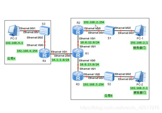
初始化
R1:
sys
sysname R1
int e1/0/0
ip add 10.0.13.1 24
int e1/0/1
ip add 10.0.12.1 24
int e2/0/0
ip add 14.1.1.1 24
q
rip
version 2
undo summary
network 10.0.0.0
q

R2:
sys
sysname R2
int e1/0/1
ip add 10.0.12.2 24
int e1/0/0
ip add 192.168.2.254 24
q
rip
version 2
undo summary
network 10.0.0.0
network 192.168.2.0
q

R3:
sys
sysname R3
int e1/0/1
ip add 10.0.13.3 24
int e1/0/0
ip add 192.168.3.254 24
q
rip
version 2
undo summary
network 10.0.0.0
network 192.168.3.0
q

R4:
sys
sysname R4
int e1/0/1
ip add 14.1.1.4 24
int e1/0/0
ip add 192.168.4.254
q

[R1]dis ip routing-table protocol rip

优化公司B的RIP网络
R2:
rip 1
undo network 192.168.2.0
import-route direct 直接进入链路,不需要路由
q

R3:
rip 1
undo network 192.168.3.0
import-route direct
q

连接公司A和公司B的网络
R1:
ip route-static 192.168.4.0 255.255.255.0 14.1.1.4
rip 1
import-route static

R2,R3:
dis ip routing-table protocol rip

R4:
ip route-static 0.0.0.0 0.0.0.0 14.1.1.1   //对面路由有点多,直接搞一条默认路由,干脆简洁

pc1 ping pc3

最终配置
display current-configuration
#
sysname R1
#
interface Ethernet0/0/1
 ip address 30.1.1.1 255.255.255.0
#
interface Ethernet0/0/2
 ip address 10.1.1.1 255.255.255.0
#
interface Ethernet0/0/3
 ip address 10.1.2.1 255.255.255.0
#
rip 1
 undo summary
 version 2
 network 30.0.0.0
 network 10.0.0.0
 import-route static
#
ip route-static 40.1.1.0 255.255.255.0 30.1.1.2
#
return

display current-configuration
#
sysname R2
#
interface Ethernet0/0/0
 ip address 20.1.1.254 255.255.255.0
#
interface Ethernet0/0/2
 ip address 10.1.1.2 255.255.255.0
#
rip 1
 undo summary
 version 2
 network 10.0.0.0
 import-route direct
#
return

display current-configuration
#
sysname R3
#
interface Ethernet0/0/0
 ip address 20.1.2.254 255.255.255.0
#
interface Ethernet0/0/3
 ip address 10.1.2.2 255.255.255.0
#
rip 1
 undo summary
 version 2
 network 10.0.0.0
 network 20.0.0.0
#
return

display current-configuration
#
sysname R4
#
interface Ethernet0/0/1
 ip address 30.1.1.2 255.255.255.0
#
interface Ethernet0/0/2
 ip address 40.1.1.254 255.255.255.0
#
interface Ethernet0/0/3
#
ip route-static 0.0.0.0 0.0.0.0 30.1.1.1
#
Return
OSPF
特点:收敛快、路由无环、扩展性好等优点
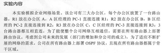
4.1 OSPF单区域配置
华为路由器规定的路由协议优先级为:
路由协议 | 优先级
————————————
DIRECT | 0
OSPF | 10
STATIC | 60
IGRP | 80
RIP | 110
OSPFASE | 150
BGP | 170
初始化:
R1:
sys
sysname R1
int g0/0/2
ip add 172.16.1.254 24
int g0/0/0
ip add 172.16.10.1 24
int g0/0/1
ip add 172.16.20.1 24
q
R2:
sys
sysname R2
int g0/0/2
ip add 172.16.2.254 24
int g0/0/0
ip add 172.16.10.2 24
int g0/0/1
ip add 172.16.30.2 24
q
R3:
sys
sysname R3
int g0/0/2
ip add 172.16.3.254 24
int g0/0/0
ip add 172.16.20.3 24
int g0/0/1
ip add 172.16.30.3 24
q
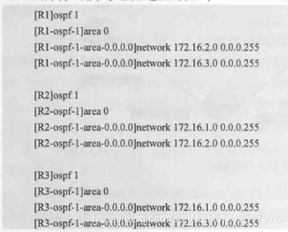
部署OSPF单区域网络
R1:
ospf 1 //1代表的是进程号,默认情况下是1
area 0
network 172.16.1.0 0.0.0.255
network 172.16.10.0 0.0.0.255
network 172.16.20.0 0.0.0.255 //本身的路由段
return
dis ospf int
R2:
ospf 1
area 0
network 172.16.2.0 0.0.0.255
network 172.16.10.0 0.0.0.255
network 172.16.30.0 0.0.0.255
return
R3:
ospf 1
area 0
network 172.16.3.0 0.0.0.255
network 172.16.20.0 0.0.0.255
network 172.16.30.0 0.0.0.255
return
R1:
dis ospf peer //查看ospf邻居状态
dis ip routing-table procotol ospf //查看路由表信息
PC1 ping PC3
个人总结:
① 基本配置
② 进入ospf模式
③ 创建骨干区域 area 0
④ 宣告网段(网段地址+反掩码)
最终配置
display current-configuration
[V200R003C00]
#
sysname R1
#
interface GigabitEthernet0/0/0
ip address 172.16.10.1 255.255.255.0
#
interface GigabitEthernet0/0/1
ip address 172.16.20.1 255.255.255.0
#
interface GigabitEthernet0/0/2
ip address 172.16.1.254 255.255.255.0
#
interface NULL0
#
ospf 1
area 0.0.0.0
network 172.16.1.0 0.0.0.255
network 172.16.10.0 0.0.0.255
network 172.16.20.0 0.0.0.255
#
Return
display current-configuration
[V200R003C00]
#
sysname R2
#
interface GigabitEthernet0/0/0
ip address 172.16.10.2 255.255.255.0
#
interface GigabitEthernet0/0/1
ip address 172.16.30.2 255.255.255.0
#
interface GigabitEthernet0/0/2
ip address 172.16.2.254 255.255.255.0
#
interface NULL0
#
ospf 1
area 0.0.0.0
network 172.16.2.0 0.0.0.255
network 172.16.10.0 0.0.0.255
network 172.16.30.0 0.0.0.255
#
Return
display current-configuration
[V200R003C00]
#
sysname R3
#
interface GigabitEthernet0/0/0
ip address 172.16.30.3 255.255.255.0
#
interface GigabitEthernet0/0/1
ip address 172.16.20.3 255.255.255.0
#
interface GigabitEthernet0/0/2
ip address 172.16.3.254 255.255.255.0
#
interface NULL0
#
ospf 1
area 0.0.0.0
network 172.16.3.0 0.0.0.255
network 172.16.20.0 0.0.0.255
network 172.16.30.0 0.0.0.255
#
return
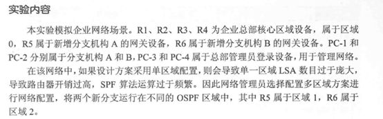
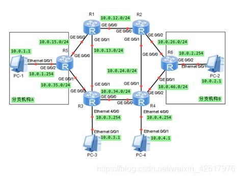
4.2 OSPF多区域配置
初始化:
R11:
sys
sysname R11
int g0/0/0
ip add 10.0.12.1 24
int g0/0/2
ip add 10.0.15.1 24
int g0/0/1
ip add 10.0.13.1 24
q
ospf 1
area 0
network 10.0.12.0 0.0.0.255
network 10.0.13.0 0.0.0.255   //主干道
q
q

R22:
sys
sysname R22
int g0/0/0
ip add 10.0.12.2 24
int g0/0/1
ip add 10.0.24.2 24
int g0/0/2
ip add 10.0.26.2 24
q
ospf 1
area 0
network 10.0.12.0 0.0.0.255
network 10.0.24.0 0.0.0.255
q
q

R33:
sys
sysname R33
int g0/0/0
ip add 10.0.34.3 24
int g0/0/1
ip add 10.0.13.3 24
int g0/0/2
ip add 10.0.35.3 24
int e0/0/0
ip add 10.0.3.254 24
q
ospf 1
area 0
network 10.0.13.0 0.0.0.255
network 10.0.34.0 0.0.0.255
network 10.0.3.0 0.0.0.255
q
q

R44:
sys
sysname R44
int g0/0/0
ip add 10.0.34.4 24
int g0/0/1
ip add 10.0.24.4 24
int g0/0/2
ip add 10.0.46.4 24
int e0/0/0
ip add 10.0.4.254 24
q
ospf 1
area 0
network 10.0.24.0 0.0.0.255
network 10.0.34.0 0.0.0.255
network 10.0.4.0 0.0.0.255
q
q

R55:
sys
sysname R55
int g0/0/2
ip add 10.0.1.254 24
int g0/0/0
ip add 10.0.15.5 24
int g0/0/1
ip add 10.0.35.5 24
q

R66:
sys
sysname R66
int g0/0/2
ip add 10.0.2.254 24
int g0/0/0
ip add 10.0.26.6 24
int g0/0/1
ip add 10.0.46.6 24
q

测试总部内2台PC连通性
10.0.3.1 ping 10.0.4.1


配置非骨干区域路由器
R5:
ospf 1
area 1
network 10.0.1.0 0.0.0.255
network 10.0.15.0 0.0.0.255
network 10.0.35.0 0.0.0.255
q
q

R1:
ospf 1
area 1
network 10.0.15.0 0.0.0.255
q
q

R3:
ospf 1
area 1
network 10.0.35.0 0.0.0.255
q
q

R5:
dis ospf peer
dis ip routing-table protocol ospf
dis ospf lsdb


配置区域2
R6:
ospf 1
area 2
network 10.0.2.0 0.0.0.255
network 10.0.26.0 0.0.0.255
network 10.0.46.0 0.0.0.255
q
q

R2:
ospf 1
area 2
network 10.0.26.0 0.0.0.255
q
q

R4:
ospf 1
area 2
network 10.0.46.0 0.0.0.255
q
q

R6
dis ip routing-table protocol ospf
dis ospf peer
dis ospf lsdb

10.0.1.1 ping 10.0.2.1
个人总结:
①	基本配置
②	配置骨干区域R1、R2、R3、R4等,但是R1、R3的一些属于area1区域;R2、R4的一些区域属于区域二,配置的时候注意点

最终配置
display current-configuration
#
sysname R1
#
interface GigabitEthernet0/0/0
ip address 10.0.12.1 255.255.255.0
#
interface GigabitEthernet0/0/1
ip address 10.0.13.1 255.255.255.0
#
interface GigabitEthernet0/0/2
ip address 10.0.15.1 255.255.255.0
#
ospf 1
area 0.0.0.0
network 10.0.12.0 0.0.0.255
network 10.0.13.0 0.0.0.255
area 0.0.0.1
network 10.0.15.0 0.0.0.255

display current-configuration
#
sysname R2
#
interface GigabitEthernet0/0/0
ip address 10.0.12.2 255.255.255.0
#
interface GigabitEthernet0/0/1
ip address 10.0.24.2 255.255.255.0
#
interface GigabitEthernet0/0/2
ip address 10.0.26.2 255.255.255.0
#
ospf 1
area 0.0.0.0
network 10.0.12.0 0.0.0.255
network 10.0.24.0 0.0.0.255
area 0.0.0.2
network 10.0.26.0 0.0.0.255

display current-configuration
#
sysname R3
#
interface Ethernet4/0/0
ip address 10.0.3.254 255.255.255.0
#
interface GigabitEthernet0/0/0
ip address 10.0.34.3 255.255.255.0
#
interface GigabitEthernet0/0/1
ip address 10.0.13.3 255.255.255.0
#
interface GigabitEthernet0/0/2
ip address 10.0.35.3 255.255.255.0
#
ospf 1
area 0.0.0.0
network 10.0.3.0 0.0.0.255
network 10.0.13.0 0.0.0.255
network 10.0.34.0 0.0.0.255
area 0.0.0.1
network 10.0.35.0 0.0.0.255

display current-configuration
#
sysname R4
#
interface Ethernet4/0/0
ip address 10.0.4.254 255.255.255.0
#
interface GigabitEthernet0/0/0
ip address 10.0.34.4 255.255.255.0
#
interface GigabitEthernet0/0/1
ip address 10.0.24.4 255.255.255.0
#
interface GigabitEthernet0/0/2
ip address 10.0.46.4 255.255.255.0
#
ospf 1
area 0.0.0.0
network 10.0.4.0 0.0.0.255
network 10.0.24.0 0.0.0.255
network 10.0.34.0 0.0.0.255
area 0.0.0.2
network 10.0.46.0 0.0.0.255

display current-configuration
#
sysname R5
#
interface GigabitEthernet0/0/0
ip address 10.0.15.5 255.255.255.0
#
interface GigabitEthernet0/0/1
ip address 10.0.35.5 255.255.255.0
#
interface GigabitEthernet0/0/2
ip address 10.0.1.254 255.255.255.0
#
ospf 1
area 0.0.0.1
network 10.0.1.0 0.0.0.255
network 10.0.15.0 0.0.0.255
network 10.0.35.0 0.0.0.255

display current-configuration
#
sysname R6
#
interface GigabitEthernet0/0/0
ip address 10.0.26.6 255.255.255.0
#
interface GigabitEthernet0/0/1
ip address 10.0.46.6 255.255.255.0
#
interface GigabitEthernet0/0/2
ip address 10.0.4.254 255.255.255.0
#
ospf 1
area 0.0.0.2
network 10.0.2.0 0.0.0.255
network 10.0.26.0 0.0.0.255
network 10.0.46.0 0.0.0.255
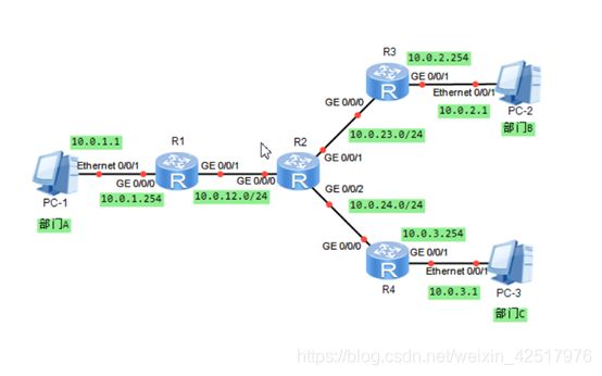
4.3 配置OSPF的认证

初始化:
R1:
sys
sysname R1
int g0/0/0
ip add 10.0.12.1 24
int loopback 0
ip add 1.1.1.1 32
q
ospf 1
area 1
network 10.0.12.0 0.0.0.255
network 1.1.1.1 0.0.0.0
q
q

R4:
sys
sysname R4
int g0/0/0
ip add 10.0.24.4 24
int loopback 0
ip add 4.4.4.4 32
q
ospf 1
area 1
network 10.0.24.0 0.0.0.255
network 4.4.4.4 0.0.0.0
q
q

R2:
sys
sysname R2
int g0/0/0
ip add 10.0.12.2 24
int g0/0/1
ip add 10.0.24.2 24
int g0/0/2
ip add 10.0.23.2 24
int loopback 0
ip add 2.2.2.2 32
q
ospf 1
area 1
network 10.0.12.0 0.0.0.255
network 10.0.24.0 0.0.0.255
area 0
network 10.0.23.0 0.0.0.255
network 2.2.2.2 0.0.0.0
q
q

R3:
sys
sysname R3
int g0/0/2
ip add 10.0.23.3 24
int g0/0/0
ip add 10.0.35.3 24
int g0/0/1
ip add 10.0.36.3 24
int loopback 0
ip add 3.3.3.3 32
q
ospf 1
area 0
network 10.0.23.0 0.0.0.255
network 10.0.35.0 0.0.0.255
network 10.0.36.0 0.0.0.255
network 3.3.3.3 0.0.0.0
q
q

R5:
sys
sysname R5
int g0/0/0
ip add 10.0.35.5 24
int loopback 0
ip add 5.5.5.5 32
q
ospf 1
area 0
network 10.0.35.0 0.0.0.255
network 5.5.5.5 0.0.0.0
q
q

R6:
sys
sysname R6
int g0/0/0
ip add 10.0.36.6 24
int loopback 0
ip add 6.6.6.6 32
q
ospf 1
area 0
network 10.0.36.0 0.0.0.255
network 6.6.6.6 0.0.0.0
q
q

R4 ping R5,R6
R1,R4 ping 6.6.6.6

配置公司分部OSPF区域明文认证
R1:
ospf 1
area 1
authentication-mode simple plain huawei1  //显示明文密码
dis this
undo authentication-mode
authentication-mode simple huawei1  //不显示明文密码
dis this

dis ospf peer brief

R2:
ospf 1
area 1
authentication-mode simple huawei1

R1:
dis ospf peer brief

R4:
ospf 1
area 1
authentication-mode simple huawei1

R2:
dis ospf peer brief

配置公司总部OSPF区域密文认证
R2,R3,R5,R6:
ospf 1
area 0
authentication-mode md5 1 huawei3
q
q

R3:
dis ospf peer brief


配置OSPF链路认证  进入对应端口配MD5认证
R2:
int g0/0/1
ospf authentication-mode md5 1 huawei5
q
dis ospf peer brief

R4:
int g0/0/0
ospf authentication-mode md5 1 huawei5
q

最终配置
display current-configuration
[V200R003C00]
#
sysname R1
#
interface GigabitEthernet0/0/0
ip address 10.0.12.1 255.255.255.0
#
interface LoopBack0
ip address 1.1.1.1 255.255.255.255
#
ospf 1
area 0.0.0.1
authentication-mode simple cipher %$%$uLH><^,C/Zu9F"Wr4`2P;4G*%$%$
network 1.1.1.1 0.0.0.0
network 10.0.12.0 0.0.0.255
#
return

display current-configuration
[V200R003C00]
#
sysname R2
#
interface GigabitEthernet0/0/0
ip address 10.0.12.2 255.255.255.0
#
interface GigabitEthernet0/0/1
ip address 10.0.24.2 255.255.255.0
ospf authentication-mode md5 1 cipher %$%$O(rq6{i@~:ZxjOVu7@f!;sq]%$%$
#
interface GigabitEthernet0/0/2
ip address 10.0.23.2 255.255.255.0
#
interface LoopBack0
ip address 2.2.2.2 255.255.255.255
#
ospf 1
area 0.0.0.0
authentication-mode md5 1 cipher %$%$o~s#(Y9'`2&uxE;1e_WE;cdisplay current-configuration
[V200R003C00]
#
sysname R3
#
interface GigabitEthernet0/0/0
ip address 10.0.35.3 255.255.255.0
#
interface GigabitEthernet0/0/1
ip address 10.0.36.3 255.255.255.0
#
interface GigabitEthernet0/0/2
ip address 10.0.23.3 255.255.255.0
#
interface LoopBack0
ip address 3.3.3.3 255.255.255.255
#
ospf 1
area 0.0.0.0
authentication-mode md5 1 cipher %$%$b>g'8Gle#Ank|^3"RnaO;EXh%$%$
network 3.3.3.3 0.0.0.0
network 10.0.23.0 0.0.0.255
network 10.0.35.0 0.0.0.255
network 10.0.36.0 0.0.0.255
#
Return

display current-configuration
[V200R003C00]
#
sysname R4
#
interface GigabitEthernet0/0/0
ip address 10.0.24.4 255.255.255.0
ospf authentication-mode md5 1 cipher %$%$82'];lU:U:auL-%{~n4P;}&X%$%$
#
interface LoopBack0
ip address 4.4.4.4 255.255.255.255
#
ospf 1
area 0.0.0.1
authentication-mode simple cipher %$%$$iC}.E|#N.N];YLjT^),;792%$%$
network 4.4.4.4 0.0.0.0
network 10.0.24.0 0.0.0.255
#
Return

display current-configuration
[V200R003C00]
#
sysname R5
#
interface GigabitEthernet0/0/0
ip address 10.0.35.5 255.255.255.0
#
#
interface LoopBack0
ip address 5.5.5.5 255.255.255.255
#
ospf 1
area 0.0.0.0
authentication-mode md5 1 cipher %$%$}sc&9m~)_VH\z7E\MphV;Fc(%$%$
network 5.5.5.5 0.0.0.0
network 10.0.35.0 0.0.0.255
#
Return

display current-configuration
[V200R003C00]
#
sysname R6
#
interface GigabitEthernet0/0/0
ip address 10.0.36.6 255.255.255.0
#
interface LoopBack0
ip address 6.6.6.6 255.255.255.255
#
ospf 1
area 0.0.0.0
authentication-mode md5 1 cipher %$%$cMpIQsdGLE([/e,rBSH%;F>O%$%$
network 6.6.6.6 0.0.0.0
network 10.0.36.0 0.0.0.255
#
Return
个人总结:
明文认证
①	进入ospf(1、2)以及所在区域 area 区域
②	配置明文认证密码 authentication-mode simple(plain)+密码
③	其他所在同区域的路由配置必须同上
密文认证:
①	进入ospf(1、2)以及所在区域 area 区域
②	配置密文认证密码 authentication-mode md5 1(认证字标识符为1)+密码
③	其他所在同区域的路由配置必须同上


链路认证模式:
①	 进入相应的链路端口(两端端口都要配置)
②	配置链路认证密码 ospf authentication-mode md5 1 +密码
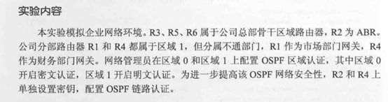
4.4 OSPF被动接口配置

最终配置
display current-configuration
sysname R1
#
interface GigabitEthernet0/0/0
ip address 10.0.3.254 255.255.255.0
#
interface GigabitEthernet0/0/1
ip address 10.0.13.1 255.255.255.0
#
ospf 1
silent-interface GigabitEthernet0/0/0
area 0.0.0.0
network 10.0.3.0 0.0.0.255
network 10.0.13.0 0.0.0.255

display current-configuration
#
sysname R2
#
interface GigabitEthernet0/0/0
ip address 10.0.23.2 255.255.255.0
#
interface GigabitEthernet0/0/1
ip address 10.0.4.254 255.255.255.0
#
ospf 1
silent-interface GigabitEthernet0/0/1
area 0.0.0.0
network 10.0.4.0 0.0.0.255
network 10.0.23.0 0.0.0.255

display current-configuration
#
sysname R3
#
interface GigabitEthernet0/0/0
ip address 10.0.13.3 255.255.255.0
#
interface GigabitEthernet0/0/1
ip address 10.0.23.3 255.255.255.0
#
interface GigabitEthernet0/0/2
ip address 10.0.30.3 255.255.255.0
#
ospf 1
area 0.0.0.0
network 10.0.13.0 0.0.0.255
network 10.0.23.0 0.0.0.255
network 10.0.30.0 0.0.0.255

display current-configuration
#
sysname R4
#
interface GigabitEthernet0/0/0
ip address 10.0.30.4 255.255.255.0
#
interface GigabitEthernet0/0/1
ip address 10.0.1.254 255.255.255.0
#
ospf enable 4 area 0.0.0.0
#
ospf 1
silent-interface all
undo silent-interface GigabitEthernet0/0/0
area 0.0.0.0
network 10.0.1.0 0.0.0.255
network 10.0.30.0 0.0.0.255

display current-configuration
#
sysname R5
#
interface GigabitEthernet0/0/0
ip address 10.0.30.5 255.255.255.0
#
interface GigabitEthernet0/0/1
ip address 10.0.2.254 255.255.255.0
#
ospf 1
silent-interface GigabitEthernet0/0/0
silent-interface GigabitEthernet0/0/1
area 0.0.0.0
network 10.0.2.0 0.0.0.255
network 10.0.30.0 0.0.0.255
个人总结:
①	 进入ospf(1、2)
② silent-interface+路由连接终端的口(禁止接口接收和发送ospf报文)
③ 端口多的话用“silent-interface all”,不用禁的就“undo silent-interface +端口”
4.5 理解OSPF Router-ID

最终配置
display current-configuration
#
 sysname R1
#
interface GigabitEthernet0/0/0
 ip address 10.0.1.254 255.255.255.0
#
interface GigabitEthernet0/0/1
 ip address 10.0.12.1 255.255.255.0
#
interface LoopBack0
 ip address 1.1.1.1 255.255.255.255
#
ospf 1 router-id 1.1.1.1
 area 0.0.0.0
  network 10.0.1.0 0.0.0.255
  network 10.0.12.0 0.0.0.255
#
Return

display current-configuration
[V200R003C00]
#
 sysname R2
#
router id 2.2.2.2
#
interface GigabitEthernet0/0/0
 ip address 10.0.12.2 255.255.255.0
#
interface GigabitEthernet0/0/1
 ip address 10.0.23.2 255.255.255.0
#
interface GigabitEthernet0/0/2
 ip address 10.0.24.2 255.255.255.0
#
interface LoopBack0
 ip address 2.2.2.2 255.255.255.0
#
ospf 1 router-id 2.2.2.2
 area 0.0.0.0
  network 10.0.12.0 0.0.0.255
  network 10.0.23.0 0.0.0.255
  network 10.0.24.0 0.0.0.255
#
Return

display current-configuration
[V200R003C00]
#
 sysname R3
#
router id 3.3.3.3
#
interface GigabitEthernet0/0/0
 ip address 10.0.23.3 255.255.255.0
#
interface GigabitEthernet0/0/1
 ip address 10.0.2.254 255.255.255.0
#
interface LoopBack0
 ip address 3.3.3.3 255.255.255.255
#
ospf 1 router-id 3.3.3.3
 area 0.0.0.0
  network 3.3.3.3 0.0.0.0
  network 10.0.23.0 0.0.0.255
#
return

display current-configuration
[V200R003C00]
#
 sysname R4
#
interface GigabitEthernet0/0/0
 ip address 10.0.24.4 255.255.255.0
#
interface GigabitEthernet0/0/1
 ip address 10.0.3.254 255.255.255.0
#
interface LoopBack0
 ip address 4.4.4.4 255.255.255.255
#
ospf 1 router-id 3.3.3.3
 area 0.0.0.0
  network 10.0.3.0 0.0.0.255
  network 10.0.24.0 0.0.0.255
#
Return
个人总结:
① 基本配置完之后,第一个配置的地址会被选为Router-ID,所以我们要第一个配置环回接口地址,也就是loopback地址,其他路由的也一样。
② 直接配置router-ID(ospf 1 router-ID 1.1.1.1,然后进入所在区域area0,再宣告各自的OSPF模式的网段)
③如果想修改router-ID的话,要这样做(ospf 1 router-ID 1.1.1.1,然后退出到用户模式重置协议进程:reset ospf process 再“Y”)
4.6 OSPF的DR与BDR

最终配置
display current-configuration
[V200R003C00]
#
 sysname R1
#
router id 1.1.1.1
#
interface GigabitEthernet0/0/0
 ip address 172.16.1.1 255.255.255.0
 ospf dr-priority 100
#
interface GigabitEthernet0/0/1
#
interface GigabitEthernet0/0/2
#
interface NULL0
#
interface LoopBack0
 ip address 1.1.1.1 255.255.255.255
#
ospf 1
 area 0.0.0.0
  network 172.16.1.0 0.0.0.255
#
Return

display current-configuration
[V200R003C00]
#
 sysname R2
#
router id 2.2.2.2
#
interface GigabitEthernet0/0/0
 ip address 172.16.1.2 255.255.255.0
 ospf dr-priority 50
#
interface GigabitEthernet0/0/1
#
interface GigabitEthernet0/0/2
#
interface NULL0
#
ospf 1
 area 0.0.0.0
  network 172.16.1.0 0.0.0.255
#
Return

display current-configuration
[V200R003C00]
#
 sysname R3
#
router id 3.3.3.3
#
interface GigabitEthernet0/0/0
 ip address 172.16.1.3 255.255.255.0
#
interface GigabitEthernet0/0/1
#
interface GigabitEthernet0/0/2
#
interface NULL0
#
ospf 1
 area 0.0.0.0
  network 172.16.1.0 0.0.0.255
#
Return

display current-configuration
[V200R003C00]
#
 sysname R4
#
router id 4.4.4.4
#
interface GigabitEthernet0/0/0
 ip address 172.16.1.4 255.255.255.0
 ospf dr-priority 0
#
interface GigabitEthernet0/0/1
#
interface GigabitEthernet0/0/2
#
interface NULL0
#
ospf 1
 area 0.0.0.0
  network 172.16.1.0 0.0.0.255
个人总结:
①	基本配置
②	配置router-id地址(环回地址)
③	进入区域宣告网段
④	重启ospf协议进程或者重启设备
⑤	进入端口,设置端口网络为广播型的网络(ospf network-type broadcast)
⑥	进入路由端口设备各自的优先级(ospf dr-priority 100)
4.7 OSPF开销值、协议优先级及计时器的修改
 `
`
最终配置
display current-configuration
[V200R003C00]
#
sysname R1
#
interface Serial4/0/0
link-protocol ppp
ip address 10.0.12.1 255.255.255.0
#
interface GigabitEthernet0/0/0
ip address 10.0.1.254 255.255.255.0
#
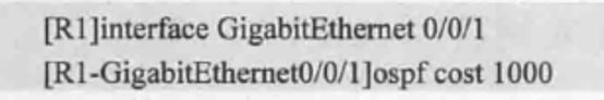
interface GigabitEthernet0/0/1
ip address 10.0.13.1 255.255.255.0
ospf cost 1000
ospf timer hello 20
#
ospf 1
preference 110
area 0.0.0.0
network 10.0.1.0 0.0.0.255
network 10.0.12.0 0.0.0.255
network 10.0.13.0 0.0.0.255
#
display current-configuration
#
sysname R2
#
#
interface Serial4/0/0
link-protocol ppp
ip address 10.0.12.2 255.255.255.0
#
interface Serial4/0/1
link-protocol ppp
ip address 10.0.24.2 255.255.255.0
#
ospf 1
area 0.0.0.0
network 10.0.12.0 0.0.0.255
network 10.0.24.0 0.0.0.255
#
display current-configuration
#
sysname R3
#
interface GigabitEthernet0/0/0
ip address 10.0.13.3 255.255.255.0
ospf timer hello 20
#
interface GigabitEthernet0/0/1
ip address 10.0.34.3 255.255.255.0
#
ospf 1
area 0.0.0.0
network 10.0.13.0 0.0.0.255
network 10.0.34.0 0.0.0.255
#
display current-configuration
#
sysname R4
#
interface Serial4/0/0
link-protocol ppp
ip address 10.0.24.4 255.255.255.0
#
interface GigabitEthernet0/0/0
ip address 10.0.34.4 255.255.255.0
#
interface GigabitEthernet0/0/1
ip address 10.0.45.4 255.255.255.0
#
ospf 1
preference 110
area 0.0.0.0
network 10.0.24.0 0.0.0.255
network 10.0.34.0 0.0.0.255
network 10.0.45.0 0.0.0.255
#
display current-configuration
#
sysname R5
#
interface GigabitEthernet0/0/0
ip address 10.0.45.5 255.255.255.0
#
interface GigabitEthernet0/0/1
ip address 10.0.2.254 255.255.255.0
#
ospf 1
area 0.0.0.0
network 10.0.2.0 0.0.0.255
network 10.0.45.0 0.0.0.255
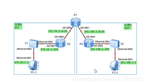
4.8 连接RIP与OSPF网络

最终配置
display current-configuration
#
sysname R1
#
interface GigabitEthernet0/0/0
 ip address 172.16.2.1 255.255.255.0
#
interface GigabitEthernet0/0/1
 ip address 192.168.2.1 255.255.255.0
#
ospf 1
 import-route rip 1
 area 0.0.0.0
  network 192.168.2.0 0.0.0.255
#
rip 1
 undo summary
 version 2
 network 172.16.2.0
 import-route ospf 1 cost 3
#
return

display current-configuration
#
sysname R2
#
interface GigabitEthernet0/0/0
 ip address 172.16.2.2 255.255.255.0
#
interface GigabitEthernet0/0/1
 ip address 172.16.1.254 255.255.255.0
#
#
rip 1
 undo summary
 version 2
 network 172.16.1.0
 network 172.16.2.0
#
return

display current-configuration
#
sysname R3
#
interface GigabitEthernet0/0/0
 ip address 192.168.1.254 255.255.255.0
#
interface GigabitEthernet0/0/1
 ip address 192.168.2.2 255.255.255.0
#
ospf 1
 area 0.0.0.0
  network 192.168.2.0 0.0.0.255
  network 192.168.1.0 0.0.0.255
#
Return
个人总结:
①	基本配置
②	配置ospf

③ 配置rip


④ 若想在ospf协议和rip协议里走rip链路,可以提高ospf优先值(优先值越高表示优先级越低)

⑤ 如果允许相同协议,可以提高其端口开销值(开销值越高表示优先级越低)
4.9 使用RIP、OSPF发布默认路由
最终配置
display current-configuration
#
sysname R1
#
interface GigabitEthernet0/0/0
 ip address 10.2.2.1 255.255.255.0
#
interface GigabitEthernet0/0/1
 ip address 20.2.2.1 255.255.255.0
#
ospf 1
 default-route-advertise always
 area 0.0.0.0
  network 20.2.2.0 0.0.0.255
#
rip 1
 undo summary
 default-route originate
 version 2
 network 10.0.0.0
#
return

display current-configuration
#
sysname R2
#
interface GigabitEthernet0/0/0
 ip address 10.2.2.2 255.255.255.0
#
interface GigabitEthernet0/0/1
 ip address 10.1.1.254 255.255.255.0
#
rip 1
 undo summary
 version 2
 network 10.0.0.0
#
return

display current-configuration
#
sysname R3
#
interface GigabitEthernet0/0/0
 ip address 20.1.1.254 255.255.255.0
#
interface GigabitEthernet0/0/1
 ip address 20.2.2.3 255.255.255.0
#
ospf 1
 area 0.0.0.0
  network 20.1.1.0 0.0.0.255
  network 20.2.2.0 0.0.0.255
#
Return
VRRP
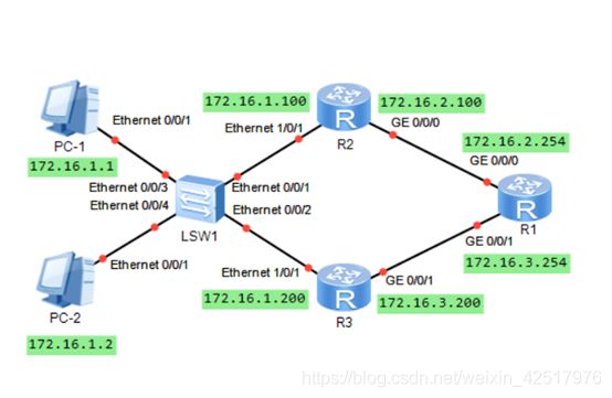
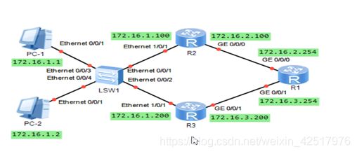
5.1 VRRP基本配置
vrrp vrid 1 virtual-ip 172.16.1.254
vrrp vrid 1 priority 110

初始化:
R1:
sys
sysname R1
int g0/0/0
ip add 172.16.2.254 24
int g0/0/1
ip add 172.16.3.254 24
q
R2:
sys
sysname R2
int g0/0/0
ip add 172.16.2.100 24
int e1/0/1
ip add 172.16.1.100 24
q
R3:
sys
sysname R3
int g0/0/0
ip add 172.16.3.200 24
int e1/0/1
ip add 172.16.1.200 24
q
部署OSPF网络
R1:
ospf 1
area 0
network 172.16.2.0 0.0.0.255
network 172.16.3.0 0.0.0.255
q
q
R3:
ospf 1
area 0
network 172.16.3.0 0.0.0.255
network 172.16.1.0 0.0.0.255
q
q
R2:
ospf 1
area 0
network 172.16.2.0 0.0.0.255
network 172.16.1.0 0.0.0.255
q
q
R1:
dis ospf peer brief
配置VRRP协议
R2:
int e1/0/1
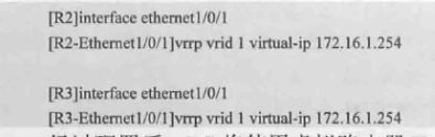
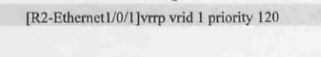
vrrp vrid 1 virtual-ip 172.16.1.254
vrrp vrid 1 priority 120
q
dis vrrp
R3:
int e1/0/1
vrrp vrid 1 virtual-ip 172.16.1.254
vrrp vrid 1 priority 110
q
dis vrrp
查看VRRP
R2:
dis vrrp
dis vrrp brief
dis vrrp int
验证VRRP主备切换
S1
int e0/0/1
shut
最终配置
display current-configuration
#
sysname R1
#
interface GigabitEthernet0/0/0
ip address 172.16.2.254 255.255.255.0
#
interface GigabitEthernet0/0/1
ip address 172.16.3.254 255.255.255.0
#
ospf 1
area 0.0.0.0
network 172.16.0.0 0.0.255.255
network 172.16.2.0 0.0.0.255
network 172.16.3.0 0.0.0.255
#
return
display current-configuration
#
sysname R2
#
interface Ethernet0/0/1
ip address 172.16.1.100 255.255.255.0
vrrp vrid 1 virtual-ip 172.16.1.254
vrrp vrid 1 priority 120
#
interface GigabitEthernet0/0/0
ip address 172.16.2.100 255.255.255.0
#
ospf 1
area 0.0.0.0
network 172.16.0.0 0.0.255.255
network 172.16.1.0 0.0.0.255
network 172.16.2.0 0.0.0.255
#
Return
display current-configuration
#
sysname R3
#
interface Ethernet0/0/1
ip address 172.16.1.200 255.255.255.0
vrrp vrid 1 virtual-ip 172.16.1.254
#
interface GigabitEthernet0/0/1
ip address 172.16.3.200 255.255.255.0
#
ospf 1
area 0.0.0.0
network 172.16.0.0 0.0.255.255
network 172.16.1.0 0.0.0.255
network 172.16.3.0 0.0.0.255
#
Return
个人总结:
① 配置基本配置以及配置OSPF宣告各自的网段信息(反掩码)
② 进入连接终端设备端的端口配置VRRP组(vrrp vrid 1 virtual-IP )
③ 进入连接终端设备端的端口配置优先值,优先值越高优先级越高(ospf默认100),配120就差不多啦
5.2 配置VRRP多备份组

最终配置
display current-configuration
#
sysname R1
#
interface GigabitEthernet0/0/0
 ip address 172.16.2.254 255.255.255.0
#
interface GigabitEthernet0/0/1
 ip address 172.16.3.254 255.255.255.0
#
ospf 1
 area 0.0.0.0
  network 172.16.2.254 0.0.0.0
  network 172.16.3.254 0.0.0.0
#
Return

display current-configuration
#
sysname R2
#
interface Ethernet0/0/1
 ip address 172.16.1.254 255.255.255.0
 vrrp vrid 1 virtual-ip 172.16.1.254
 vrrp vrid 1 priority 120
 vrrp vrid 2 virtual-ip 172.16.1.253
 vrrp vrid 2 priority 200
 vrrp vrid 2 preempt-mode disable
#
interface GigabitEthernet0/0/0
 ip address 172.16.2.100 255.255.255.0
#
ospf 1
 area 0.0.0.0
  network 172.16.1.100 0.0.0.0
  network 172.16.2.100 0.0.0.0
#
Return

display current-configuration
#
sysname R3
#
interface Ethernet0/0/0
#
interface Ethernet0/0/1
 ip address 172.16.1.200 255.255.255.0
 vrrp vrid 1 virtual-ip 172.16.1.254
 vrrp vrid 1 priority 254
 vrrp vrid 2 virtual-ip 172.16.1.253
 vrrp vrid 2 priority 120
#
interface GigabitEthernet0/0/1
 ip address 172.16.3.200 255.255.255.0
#
ospf 1
 area 0.0.0.0
  network 172.16.1.200 0.0.0.0
  network 172.16.3.200 0.0.0.0
#
Return
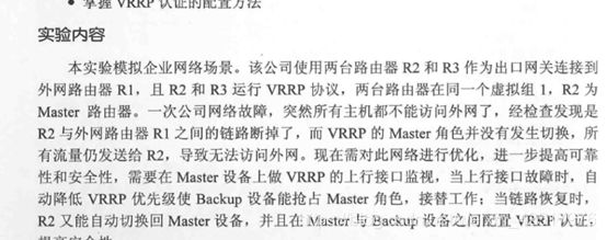
5.3 配置VRRP的跟踪接口及认证
最终配置
display current-configuration
sysname R1
interface GigabitEthernet0/0/0
 ip address 172.16.2.254 255.255.255.0
#
interface GigabitEthernet0/0/1
 ip address 172.16.3.254 255.255.255.0

display current-configuration
sysname R2
interface Ethernet1/0/1
 ip address 172.16.1.100 255.255.255.0
 vrrp vrid 1 virtual-ip 172.16.1.254
 vrrp vrid 1 priority 120
 vrrp vrid 1 track interface GigabitEthernet0/0/0 reduced 50
 vrrp vrid 1 authentication-mode md5 %$%$!B56J6".AW`Os:5nOIM96GU"%$%$
#
interface GigabitEthernet0/0/0
 ip address 172.16.2.100 255.255.255.0

display current-configuration
sysname R3
interface Ethernet1/0/1
 ip address 172.16.1.200 255.255.255.0
 vrrp vrid 1 virtual-ip 172.16.1.254
 vrrp vrid 1 authentication-mode md5 %$%$xASELV]Z77V(rDFgUna@6FBd%$%$
#
interface GigabitEthernet0/0/1
 ip address 172.16.3.200 255.255.255.0
个人总结:
①	配置基本配置以及配置OSPF宣告各自的网段信息(反掩码)
②	进入端口配置优先值(一个已经默认100,所以配置一个就好,但是也要把它划入vrrp组并配置好IP)
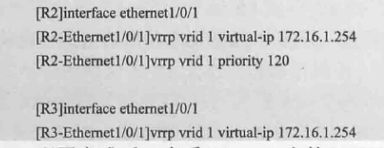
③ 配置端口监视功能,当主端口出现问题时,自动降低优先值,然后备份vrrp链路用上(下面的:vrrp vrid 1 track interface gigabitethernet 0/0/0 reduced 50 表示自动降值50)
④ 配置认证方式

基础过滤工具
6.1 配置基本的访问控制列表
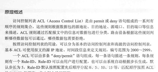
Rule-ID越小越优先

初始化并配置OSPF网络
R1:
sys
sysname R1
int g0/0/0
ip add 10.0.13.1 24
int loopback 0
ip add 1.1.1.1 32
q
ospf 1
area 0
network 1.1.1.1 0.0.0.0
network 10.0.13.0 0.0.0.255
q
q
R2:
sys
sysname R2
int g0/0/0
ip add 10.0.23.1 24
int loopback 0
ip add 2.2.2.2 32
q
ospf 1
area 0
network 10.0.23.0 0.0.0.255
network 2.2.2.2 0.0.0.0
q
q
R3:
sys
sysname R3
int g0/0/0
ip add 10.0.13.3 24
int g0/0/1
ip add 10.0.23.3 24
int g0/0/2
ip add 10.0.34.3 24
int loopback 0
ip add 3.3.3.3 32
q
ospf 1
area 0
network 3.3.3.3 0.0.0.0
network 10.0.13.0 0.0.0.255
network 10.0.23.0 0.0.0.255
network 10.0.34.0 0.0.0.255
q
q
R4:
sys
sysname R4
int g0/0/0
ip add 10.0.34.4 24
int loopback 0
ip add 4.4.4.4 32
q
ospf 1
area 0
network 4.4.4.4 0.0.0.0
network 10.0.34.0 0.0.0.255
q
q
查看R1的路由表
dis ip routing-table protocol ospf
ping 4.4.4.4
R2:
ping 4.4.4.4
配置基本ACL列表
R4:
user-int vty 0 4
authentication-mode passwod //不得
用authentication-mode none 替代
R1,R2:
telnet 4.4.4.4
ping 4.4.4.4
R4:
acl 2000
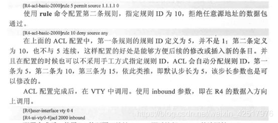
rule 5 permit source 1.1.1.1 0
rule 10 deny source any
user-int vty 0 4
acl 2000 inbound
q
R1,R2:
telnet -a 1.1.1.1 4.4.4.4
ping 4.4.4.4
基本ACL的语法规则
R4:
dis acl all
acl 2000
rule 15 permit source 4.4.4.0
此时在R3上telnet 4.4.4.4应该不得
R4:
acl 2000
undo acl 15
acl 8 permit source 4.4.4.0
q
此时在R3上telnet 4.4.4.4应该得
最终配置
display current-configuration
[V200R003C00]
#
sysname R1
#
interface GigabitEthernet0/0/0
ip address 10.0.13.1 255.255.255.0
#
interface LoopBack0
ip address 1.1.1.1 255.255.255.255
#
ospf 1
area 0.0.0.0
network 1.1.1.1 0.0.0.0
network 10.0.13.0 0.0.0.255
#
return
display current-configuration
[V200R003C00]
#
sysname R2
#
interface GigabitEthernet0/0/0
ip address 10.0.23.2 255.255.255.0
#
ospf 1
area 0.0.0.0
network 10.0.23.0 0.0.0.255
#
return
display current-configuration
[V200R003C00]
#
sysname R3
#
interface GigabitEthernet0/0/0
ip address 10.0.13.3 255.255.255.0
#
interface GigabitEthernet0/0/1
ip address 10.0.23.3 255.255.255.0
#
interface GigabitEthernet0/0/2
ip address 10.0.34.3 255.255.255.0
#
interface LoopBack0
ip address 3.3.3.3 255.255.255.0
#
ospf 1
area 0.0.0.0
network 3.3.3.3 0.0.0.0
network 10.0.13.0 0.0.0.255
network 10.0.23.0 0.0.0.255
network 10.0.34.0 0.0.0.255
#
Return
display current-configuration
[V200R003C00]
#
sysname R4
#
acl number 2000
rule 5 permit source 1.1.1.1 0
rule 8 permit source 3.3.3.3 0
rule 10 deny
#
interface GigabitEthernet0/0/0
ip address 10.0.34.4 255.255.255.0
#
interface LoopBack0
ip address 4.4.4.4 255.255.255.0
#
ospf 1
area 0.0.0.0
network 4.4.4.4 0.0.0.0
network 10.0.34.0 0.0.0.255
#
user-interface vty 0 4
acl 2000 inbound
set authentication password cipher %$%$8ir_JOp^L>rX3)$*,VL0,#[Yk^Ym76n[+Mw]h#1iCyE4#[\,%$%$
#
Return
个人总结:
① 配置基本配置(这里LOOPBACK)以及配置ospf协议
② 配置ACL


![]()
③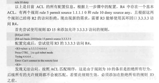
④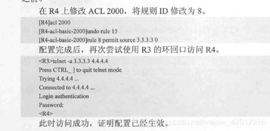
6.2 配置高级的访问控制列表

初始化并配置OSPF网络
R1:
sys
sysname R1
int g0/0/0
ip add 10.0.13.1 24
int loopback 0
ip add 1.1.1.1 32
q
ospf 1
area 0
network 1.1.1.1 0.0.0.0
network 10.0.13.0 0.0.0.255
q
q

R2:
sys
sysname R2
int g0/0/0
ip add 10.0.23.1 24
int loopback 0
ip add 2.2.2.2 32
q
ospf 1
area 0
network 10.0.23.0 0.0.0.255
network 2.2.2.2 0.0.0.0
q
q

R3:
sys
sysname R3
int g0/0/0
ip add 10.0.13.3 24
int g0/0/1
ip add 10.0.23.3 24
int g0/0/2
ip add 10.0.34.3 24
int loopback 0
ip add 3.3.3.3 32
q
ospf 1
area 0
network 3.3.3.3 0.0.0.0
network 10.0.13.0 0.0.0.255
network 10.0.23.0 0.0.0.255
network 10.0.34.0 0.0.0.255
q
q

R4:
sys
sysname R4
int g0/0/0
ip add 10.0.34.4 24
int loopback 0
ip add 4.4.4.4 32
int loopback 1
ip add 40.40.40.40 32
q
ospf 1
area 0
network 4.4.4.4 0.0.0.0
network 40.40.40.40 0.0.0.0
network 10.0.34.0 0.0.0.255
q
q

R1:  dis ip routing-table protocol ospf

配置R4的Tenlnet服务
R4
user-int vty 0 4
authentication-mode none
q

测试R1和R2连R4的Telnet
telnet -a 1.1.1.1 4.4.4.4
telnet -a 1.1.1.1 40.40.40.40

配置高级ACL
R4:
acl 3000
rule 5 permit ip source 1.1.1.1 0 destination 4.4.4.4 0
user-int vty 0 4
acl 3000 inbound
q

dis acl all
dis acl 3000
最终配置
display current-configuration
[V200R003C00]
#
sysname R1
#
interface GigabitEthernet0/0/0
ip address 10.0.13.1 255.255.255.0
#
interface LoopBack0
ip address 1.1.1.1 255.255.255.255
#
ospf 1
area 0.0.0.0
network 1.1.1.1 0.0.0.0
network 10.0.13.0 0.0.0.255
#
return

display current-configuration
[V200R003C00]
#
sysname R2
#
interface GigabitEthernet0/0/0
ip address 10.0.23.2 255.255.255.0
#
ospf 1
area 0.0.0.0
network 10.0.23.0 0.0.0.255
#
return

display current-configuration
[V200R003C00]
#
sysname R3
#
interface GigabitEthernet0/0/0
ip address 10.0.13.3 255.255.255.0
#
interface GigabitEthernet0/0/1
ip address 10.0.23.3 255.255.255.0
#
interface GigabitEthernet0/0/2
ip address 10.0.34.3 255.255.255.0
#
interface LoopBack0
ip address 3.3.3.3 255.255.255.0
#
ospf 1
area 0.0.0.0
network 3.3.3.3 0.0.0.0
network 10.0.13.0 0.0.0.255
network 10.0.23.0 0.0.0.255
network 10.0.34.0 0.0.0.255
#
Return

display current-configuration
[V200R003C00]
#
sysname R4
#
acl number 2000
rule 5 permit source 1.1.1.1 0
rule 8 permit source 3.3.3.3 0
rule 10 deny
#
acl number 3000
rule 5 permit ip source 1.1.1.1 0 destination 4.4.4.4 0
#
interface GigabitEthernet0/0/0
ip address 10.0.34.4 255.255.255.0
#
interface LoopBack0
ip address 4.4.4.4 255.255.255.0
#
interface LoopBack1
ip address 40.40.40.40 255.255.255.255
#
ospf 1
area 0.0.0.0
network 4.4.4.4 0.0.0.0
network 10.0.34.0 0.0.0.255
network 40.40.40.40 0.0.0.0
#
user-interface vty 0 4
acl 3000 inbound
authentication-mode password
set authentication password cipher %$%$2cAF6"*I=@yM\CNaL&V.,"\./I<`X#iO{)7]"/Lz4d(3"\1,%$%$
#
Return
个人总结:
① 基本配置以及配置ospf协议
② 配置Tenlnet

③ 创建高级ACL


④ 调用ACL到vty下

6.3 配置前缀列表
R1:
sys
sysname R1
int g0/0/0
ip add 40.1.1.1 24
int g0/0/1
ip add 20.1.1.1 24
int g0/0/2
ip add 30.1.1.1 24
q
rip
version 2
undo summary
network 40.0.0.0
network 20.0.0.0
network 30.0.0.0
q

R2:
sys
sysname R2
int g0/0/0
ip add 11.1.1.2 24
int g0/0/1
ip add 20.1.1.2 24
q
rip
version 2
undo summary
network 11.0.0.0
network 20.0.0.0
q


R3:
sys
sysname R3
int g0/0/0
ip add 11.1.1.11 25
int g0/0/2
ip add 30.1.1.3 24
q
rip
version 2
undo summary
network 11.0.0.0
network 30.0.0.0
q

R4:
sys
sysname R4
int g0/0/0
ip add 40.1.1.4 24
q
rip
version 2
undo summary
network 40.0.0.0
q

R4:
dis ip routing-table
ping 11.1.1.1
tracert 11.1.1.1

配置ACL过滤路由
R1:
acl 2000
rule 5 deny source 11.1.1.0 0.0.0.0
rule 10 permit source any
rip
filter-policy 2000 import
q
dis ip routing-table

配置前缀列表控制过滤路由
R1:
ip ip-prefix 1 deny 11.1.1.0 25
ip ip-prefix 1 permit 0.0.0.0 less-equal 32

最终配置
display current-configuration
#
sysname R1
#
interface GigabitEthernet0/0/0
 ip address 40.1.1.1 255.255.255.0
#
interface GigabitEthernet0/0/1
 ip address 20.1.1.1 255.255.255.0
#
interface GigabitEthernet0/0/2
 ip address 30.1.1.1 255.255.255.0
#
rip 1
 undo summary
 version 2
 network 20.0.0.0
 network 30.0.0.0
 network 40.0.0.0
 filter-policy ip-prefix 1 import
#
ip ip-prefix 1 index 30 deny 10.1.1.0 25 greater-equal 25 less-equal 25
ip ip-prefix 1 index 40 permit 0.0.0.0 0 less-equal 32
#
Return

display current-configuration
#
sysname R2
#
interface GigabitEthernet0/0/0
 ip address 10.1.1.2 255.255.255.0
#
interface GigabitEthernet0/0/1
 ip address 20.1.1.2 255.255.255.0
##
rip 1
 undo summary
 version 2
 network 10.0.0.0
 network 20.0.0.0
#
Return

display current-configuration
#
sysname R3
#
interface GigabitEthernet0/0/0
 ip address 10.2.2.3 255.255.255.0
#
interface GigabitEthernet0/0/2
 ip address 30.1.1.3 255.255.255.0
#
rip 1
 undo summary
 version 2
 network 10.0.0.0
 network 30.0.0.0
#
Return

display current-configuration
#
sysname R4
#
interface GigabitEthernet0/0/0
 ip address 40.1.1.4 255.255.255.0
#
rip 1
 undo summary
 version 2
 network 40.0.0.0
#
Return
有点复杂,看书或者百度吧
交换机基础配置
7.1 交换机基础配置


S1
Sys
Int e0/0/1
undo negotication auto //关闭自动汇总
dupex full  //开启全双工
speed 10  //控制流量通过为10M
undo shut

auto duplex full  //使接口的可协商双工模式变为双工模式
最终配置
display current-configuration
#
sysname S1
#
interface Ethernet0/0/1
 undo negotiation auto
 speed 10
#
interface GigabitEthernet0/0/1
 port media type copper
  undo negotiation auto
  speed 100

display current-configuration
#
sysname S2
#
interface Ethernet0/0/1
 undo negotiation auto
 speed 10
#
interface GigabitEthernet0/0/2
 port media type copper
  undo negotiation auto
  speed 100

display current-configuration
#
sysname S3
#
interface GigabitEthernet0/0/1
 undo negotiation auto
 speed 100
#
interface GigabitEthernet0/0/2
 undo negotiation auto
 speed 100
#
7.2 理解ARP及Proxy ARP


初始化
R1
sys
int g0/0/1
ip add 10.1.1.254 24
int g0/0/2
ip add 10.1.2.254 24
quit

display arp all

arp static 10.1.1.1 5489-98CF-2803  //绑定物理地址

int g0/0/1
arp-proxy enable    //终端没有配置网关,路由开启ARP代理功能也可以通信
int g0/0/2
arp-proxy enable
最终配置
display current-configuration
#
sysname R1
#
interface GigabitEthernet0/0/1
 ip address 10.1.1.254 255.255.255.0
 arp-proxy enable
#
interface GigabitEthernet0/0/2
 ip address 10.1.2.254 255.255.255.0
 arp-proxy enable
#
arp static 10.1.1.1 5489-98cf-1852
arp static 10.1.1.2 5489-98cf-4f63
arp static 10.1.2.3 5489-98cf-5404
#
初始化
R1
sys
int g0/0/1
ip add 10.1.1.254 24
int g0/0/2
ip add 10.1.2.254 24
quit
display arp all
arp static 10.1.1.1 5489-98CF-2803 //绑定物理地址
int g0/0/1
arp-proxy enable //终端没有配置网关,路由开启ARP代理功能也可以通信
int g0/0/2
arp-proxy enable
最终配置
display current-configuration
sysname R1
interface GigabitEthernet0/0/1
ip address 10.1.1.254 255.255.255.0
arp-proxy enable
interface GigabitEthernet0/0/2
ip address 10.1.2.254 255.255.255.0
arp-proxy enable
arp static 10.1.1.1 5489-98cf-1852
arp static 10.1.1.2 5489-98cf-4f63
arp static 10.1.2.3 5489-98cf-5404
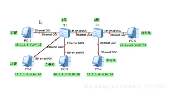
S1
sys
vlan 10
vlan 20
q
display vlan

S2
sys
vlan batch 30 40
q
display vlan

S1
int e0/0/1
port link-type access
port default vlan 10

int e0/0/2
port link-type access
port default vlan 10

int e0/0/3
port link-type access
port default vlan 20

display vlan

S2
int e0/0/1
port link-type access
port default vlan 30

int e0/0/2
port link-type access
port default vlan 40

display vlan
display port vlan

自己加的实验
S1
int e0/0/5
port link-type trunk
port trunk allow-pass vlan all

S2
vlan 10
int e0/0/2
port link-type access
port default vlan 10
int e0/0/5
port link-type trunk
port trunk allow-pass vlan all


第2次实验:
S2:
sys
sysname S2
vlan batch 20 30
int e0/0/2
port link-type access
port default vlan 20
int e0/0/1
port link-type access
port default vlan 30
q
dis current-configuration

最终配置
display current-configuration
#
sysname S1
#
vlan batch 10 20
#
interface Ethernet0/0/1
 port link-type access
 port default vlan 10
#
interface Ethernet0/0/2
 port link-type access
 port default vlan 10
#
interface Ethernet0/0/3
 port link-type access
 port default vlan 20

display current-configuration
sysname S2
#
vlan batch 30 40
#
interface Ethernet0/0/1
port link-type access
port default vlan 30
#
interface Ethernet0/0/2
 port link-type access
 port default vlan 40
8.2 跨交换机实现VLAN间通信

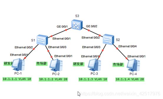
1.创建VLAN
S1:
sys
sysname S1
vlan 10
description RD
vlan 20
description Market
int e0/0/2
port link-type access
port default vlan 10
int e0/0/3
port link-type access
port default vlan 20
q

S2:
sys
sysname S2
vlan 10
description RD
vlan 20
description Market
int e0/0/3
port link-type access
port default vlan 10
int e0/0/4
port link-type access
port default vlan 20
q

S3:
sys
sysname S3
vlan 10
description RD
vlan 20
description Market
q

display vlan
S3:
display vlan summary
S1 S2:
display port vlan

2.测试PC1和PC3的连通性

3.配置Trunk端口
S1:
int e0/0/1
port link-type trunk
port trunk allow-pass vlan 10 20
q

S2:
int e0/0/2
port link-type trunk
port trunk allow-pass vlan 10 20
q

display port vlan

S3:
int g0/0/1
port link-type trunk
port trunk allow-pass vlan all
int g0/0/2
port link-type trunk
port trunk allow-pass vlan all
q

最终配置
display current-configuration
#
sysname S1
#
vlan batch 10 20
#
vlan 10
 description R&D
vlan 20
 description Market
#
interface Ethernet0/0/1
 port link-type trunk
 port trunk allow-pass vlan 10 20
#
interface Ethernet0/0/2
 port link-type access
 port default vlan 10
#
interface Ethernet0/0/3
 port link-type access
 port default vlan 20
#
Return

display current-configuration
#
sysname S2
#
vlan batch 10 20
#
vlan 10
 description R&D
vlan 20
 description Market
#
interface Ethernet0/0/2
 port link-type trunk
 port trunk allow-pass vlan 10 20
#
interface Ethernet0/0/3
 port link-type access
 port default vlan 10
#
interface Ethernet0/0/4
 port link-type access
 port default vlan 20
#
Return

display current-configuration
#
sysname S3
#
vlan batch 10 20
#
vlan 10
 description R$D
vlan 20
 description Market
#
interface GigabitEthernet0/0/1
 port link-type trunk
 port trunk allow-pass vlan 2 to 4094
#
interface GigabitEthernet0/0/2
 port link-type trunk
 port trunk allow-pass vlan 2 to 4094
#
Return
8.3 理解Hybrid接口的应用


实现VLAN10、VLAN20内互访,之间不能访:
(undo port default vlan)
(undo port link-type access)

法一:Access+Trunk
法二:Hybrid

法二:
S1:
sys
sysname S1
vlan 10
description HR
vlan 20
description Market
int e0/0/2
port link-type hybrid
port hybrid untagged vlan 20
port hybrid pvid vlan 20
int e0/0/3
port link-type hybrid
port hybrid untagged vlan 10
port hybrid pvid vlan 10
int e0/0/1
port link-type hybrid
port hybrid tagged vlan 1 10 20 默认的1要通过

q

S2:
sys
sysname S2
vlan 10
description HR
vlan 20
description Market
int e0/0/2
port link-type hybrid
port hybrid untagged vlan 20
port hybrid pvid vlan 20
int e0/0/3
port link-type hybrid
port hybrid untagged vlan 10
port hybrid pvid vlan 10
int e0/0/1
port link-type hybrid
port hybrid tagged vlan 1 10 20
q

测试1-4号PC连通性

配置IT部门访问 VLAN 10和 VLAN 20
S1:
int e0/0/4
port link-type hybrid
port hybrid pvid vlan 30
port hybrid untagged vlan 10 20
int e0/0/2
port hybrid untagged vlan 30
int e0/0/3
port hybrid untagged vlan 30
q

S2:
int e0/0/2
port hybrid untagged vlan 30
int e0/0/3
port hybrid untagged vlan 30
q
最终配置
display current-configuration
#
sysname S1
#
vlan batch 10 20 30
#
interface Ethernet0/0/1
 port hybrid tagged vlan 10 20 30
#
interface Ethernet0/0/2
 port hybrid pvid vlan 20
 port hybrid untagged vlan 20 30
#
interface Ethernet0/0/3
 port hybrid pvid vlan 10
 port hybrid untagged vlan 10 30
#
interface Ethernet0/0/4
 port hybrid pvid vlan 30
 port hybrid untagged vlan 10 20 30
#

display current-configuration
#
sysname S2
#
vlan batch 10 20 30
#
interface Ethernet0/0/1
 port hybrid tagged vlan 10 20 30
#
interface Ethernet0/0/2
 port hybrid pvid vlan 20
 port hybrid untagged vlan 20 30
#
interface Ethernet0/0/3
 port hybrid pvid vlan 10
 port hybrid untagged vlan 10 30
#
8.4 利用单臂路由实现VLAN间路由

初始化:
S2:
sys
sysname S2
vlan 10
description HR
vlan 20
description Market
int e0/0/1
port link-type access
port default vlan 10
int e0/0/2
port link-type access
port default vlan 20
int g0/0/2
port link-type trunk
port trunk allow-pass vlan 10 20
q

S3:
sys
sysname S3
vlan 30
description Manager
int e0/0/1
port link-type access
port default vlan 30
int g0/0/2
port link-type trunk
port trunk allow-pass vlan 30
q

S1:
sys
sysname S1
vlan batch 10 20 30
int g0/0/2
port link-type trunk
port trunk allow-pass vlan 10 20
int g0/0/3
port link-type trunk
port trunk allow-pass vlan 30
int g0/0/1
port link-type trunk
port trunk allow-pass vlan 10 20 30
q

R1:
sys
sysname R1
vlan batch 10 20 30
int g0/0/1.1
ip address 192.168.1.254 24
undo shut
int g0/0/1.2
ip address 192.168.2.254 24
undo shut
int g0/0/1.3
ip address 192.168.3.254 24
undo shut
q

R1上做单臂路由:
R1:
int g0/0/1.1
dot1q termination vid 10
arp broadcast enable
int g0/0/1.2
dot1q termination vid 20
arp broadcast enable
int g0/0/1.3
dot1q termination vid 30
arp broadcast enable
q


display ip int brief  //查看接口状态
display ip routing-table
最终配置
display current-configuration
sysname S1
#
vlan batch 10 20 30
interface GigabitEthernet0/0/1
 port link-type trunk
 port trunk allow-pass vlan 2 to 4094
#
interface GigabitEthernet0/0/2
 port link-type trunk
 port trunk allow-pass vlan 2 to 4094
#
interface GigabitEthernet0/0/3
 port link-type trunk
 port trunk allow-pass vlan 2 to 4094

display current-configuration
#
sysname S2
#
vlan batch 10 20
#
interface Ethernet0/0/1
 port link-type access
 port default vlan 10
#
interface Ethernet0/0/2
 port link-type access
 port default vlan 20
interface GigabitEthernet0/0/2
 port link-type trunk
port trunk allow-pass vlan 2 to 4094

display current-configuration
#
sysname S3
#
vlan batch 30
#
interface Ethernet0/0/1
 port link-type access
 port default vlan 30
#
interface GigabitEthernet0/0/2
 port link-type trunk
port trunk allow-pass vlan 2 to 4094

display current-configuration
sysname R1
#
interface GigabitEthernet0/0/1
#
interface GigabitEthernet0/0/1.1
 dot1q termination vid 10
 ip address 10.1.1.254 255.255.255.0
 arp broadcast enable
 control-vid 10 dot1q-termination
#
interface GigabitEthernet0/0/1.2
 dot1q termination vid 20
 ip address 20.1.1.254 255.255.255.0
 arp broadcast enable
 control-vid 20 dot1q-termination
#
interface GigabitEthernet0/0/1.3
 dot1q termination vid 30
 ip address 30.1.1.254 255.255.255.0
 arp broadcast enable
control-vid 30 dot1q-termination
#
8.5 利用三层交换机实现VLAN间路由


初始化:
S1:
sys
sysname S1
vlan 10
description XiaoShou
vlan 20
description KeFu
int g0/0/1
port link-type access
port default vlan 10
int g0/0/2
port link-type access
port default vlan 10
int g0/0/3
port link-type access
port default vlan 20
q

配置三层交换
S1:
int vlanif 10
ip add 192.168.1.254 24
int vlanif 20
ip add 192.168.2.254 24
q


dis ip int brief
最终配置
display current-configuration
#
sysname S1
#
VLAN batch 10 20
#
interface VLANif10
 ip address 192.168.1.254 255.255.255.0
#
interface VLANif20
 ip address 192.168.2.254 255.255.255.0
#
interface GigabitEthernet0/0/1
 port link-type access
 port default VLAN 10
#
interface GigabitEthernet0/0/2
 port link-type access
 port default VLAN 10
#
interface GigabitEthernet0/0/3
 port link-type access
 port default VLAN 20
#
interface GigabitEthernet0/0/4
 port link-type access
 port default VLAN 10
#
return
生成树
9.1 STP配置和选路规则

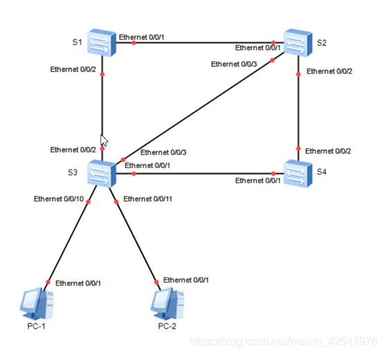
初始化:
S1:
sys
sysname S1
stp enable
stp mode stp

S2:
sys
sysname S2
stp enable
stp mode stp

S3:
sys
sysname S3
stp enable
stp mode stp

S4:
sys
sysname S4
stp enable
stp mode stp

查看STP配置
S1:
dis stp
dis stp brief

配置交换机优先级
法一:
S1:
stp priority 0
S2:
stp priority 4096


还原默认优先级
undo stp priority

法二:
S1:
stp root primary
S2:
stp root secondary

理解根端口的选举
S4:
dis stp int e0/0

Hello 2s
MaxAge 20s
FwDly 15s
RemHop 20s

//缺省情况下端口优先级为128.
端口优先级取值越小,则优先级高
int g0/0/9
stp port priority 32
int g0/0/10
stp port priority 16
//10的端口优先级小于9的端口优先级,所以10端口优先级
高于9端口,10端口为根端口

dis stp brief
dis stp int g0/0/9
开启边缘端口:stp edged-port enable
端口组:port-group group-member Ethernet 0/0/10 to Ethernet 0/0/11
最终配置
display current-configuration
#
sysname S1
#
stp mode stp
stp instance 0 root primary
#
return

display current-configuration
#
sysname S2
#
stp mode stp
stp instance 0 root secondary
#
return

display current-configuration
#
sysname S3
#
stp instance 0 priority 4096
#
stp mode stp
#
interface Ethernet0/0/2
 stp instance 0 cost 2
#
return

display current-configuration
#
sysname S4
#
stp mode stp
#
interface Ethernet0/0/2
 stp instance 0 cost 2000
#
Return
个人总结:
① 开启stp服务(stp enable;以及普通stp;stp mode stp)
② 设置根备交换机(stp root priority,stp root secondary 另一个 stp priority 4096 默认为32768 所以比其他的小了就是根)
③ 设置根端口(查看端口开销值:dis stp inter 端口 ,然后对比设置,值越小越优先)
④ 貌似只有备份交换机才有指定端口ALTE,不太确定
9.2 配置STP定时器

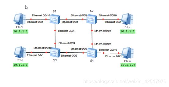
初始化(开启STP)
S1:
stp enable
stp mode stp
stp root primary

S2:
stp enable
stp mode stp
stp root secondary

S3:
stp enable
stp mode stp

S4:
stp enable
stp mode stp


测试:
S1:
stp timer forward-delay 2000
stp bridge-diameter 3

最终配置
display current-configuration
#
sysname S1
#
stp mode stp
stp timer-factor 10
stp instance 0 root primary
#
interface Ethernet0/0/1
 stp bpdu-filter enable

display current-configuration
#
sysname S2
#
stp mode stp
stp timer-factor 10
stp instance 0 root secondary

display current-configuration
#
sysname S3
#
stp mode stp
stp timer-factor 10

display current-configuration
#
sysname S4
#
stp mode stp
stp timer-factor 10
个人总结:
①	 基本配置
②	开启stp,配置根、备交换机
③	设时间(stp timer forward-dely 2000 默认1500cs,这个stp bridge-diamter 3 设置网络直径也可以修改stp计时器)
9.3 RSTP基础配置
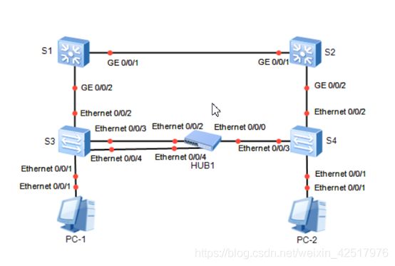
初始化
S1,S,S3,S4:
stp mode rstp
dis stp brief
dis stp

S1: stp root primary
S2: stp root secondary

观察:
S2:
int g0/0/1
shutdown
dis stp brief


清除S1上配置的STP优先级和开销
undo stp priority
int g0/0/9
undo stp cost

配置边缘端口
int e 0/0/1
stp edge-port enable

配置BPDU保护功能
//边缘端口直接与用户终端相连,正常情况下不会收到BPDU报文。
  但如果攻击者向交换机的边缘端口发送伪造的BPDU报文,交换机会自动将边缘端口设置为非边缘端口,并重新进行生成树计算,从而引起网络震荡。
  在交换机上配置BPDU保护功能,可以防止该类攻击。
[S1] stp bpdu-protection
[S2] stp bpdu-protection


配置环路保护功能
//在运行RSTP协议的网络中,交换机依靠不断接收来自上游设备的BPDU报文维持根端口和Alternate端口的状态。如果由于链路拥塞或单向链路故障导致交换机收不到来自上游设备的BPDU报文,交换机会重新选择根端口。
  原先的根端口会转变为指定端口,而原先的阻塞端口会迁移到转发状态,从而会引起网络环路。可以在交换机上配置环路保护功能,避免此种情况发生。
int g0/0/9
stp loop-protection
最终配置
display current-configuration
#
sysname S1
#
stp mode rstp
stp instance 0 root primary
#
#
interface GigabitEthernet0/0/1
#
interface GigabitEthernet0/0/2
#
interface GigabitEthernet0/0/3
#
interface GigabitEthernet0/0/4
#

display current-configuration
#
sysname S2
#
stp mode rstp
stp instance 0 root secondary
#
interface GigabitEthernet0/0/1
#
interface GigabitEthernet0/0/2
#
interface GigabitEthernet0/0/3
#
interface GigabitEthernet0/0/4
#

display current-configuration
#
sysname S3
#
stp mode rstp
#
interface Ethernet0/0/1
#
interface Ethernet0/0/2
#
interface Ethernet0/0/3
#
interface Ethernet0/0/4
#

display current-configuration
#
sysname S4
#
stp mode rstp
#
interface Ethernet0/0/1
 stp edged-port enable
#
interface Ethernet0/0/2
#
interface Ethernet0/0/3
#
interface Ethernet0/0/4
9.4 MSTP基础配置

初始化
S1:
sys
sysname S1
vlan batch 10 20
int e0/0/1
port link-type trunk
port trunk allow-pass vlan all
int e0/0/2
port link-type trunk
port trunk allow-pass vlan all
int e0/0/3
port link-type access
port default vlan 10
q

S2:
sys
sysname S2
vlan batch 10 20
int e0/0/1
port link-type trunk
port trunk allow-pass vlan all
int e0/0/2
port link-type trunk
port trunk allow-pass vlan all
int e0/0/3
port link-type access
port default vlan 20
q

S3:
sys
sysname S3
vlan batch 10 20
int e0/0/1
port link-type trunk
port trunk allow-pass vlan all
int e0/0/2
port link-type trunk
port trunk allow-pass vlan all
int e0/0/3
port link-type access
port default vlan 10
int e0/0/4
port link-type access
port default vlan 20
q


测试:
S1,S2,S3:
stp region-configuration
region-name huawei
revision-level 1
instance 1 vlan 10
instance 2 vlan 20
active region-configuration

dis stp region-configuration

dis stp instance 0 brief
dis stp instance 1 brief
dis stp instance 2 brief

S2:
stp instance 2 priority 0

dis stp instance 2 brief


最终配置
display current-configuration
#
sysname S1
#
vlan batch 10 20
#
stp instance 1 root primary
stp instance 2 root secondary
#
stp region-configuration
 region-name huawei
 revision-level 1
 instance 1 vlan 10
 instance 2 vlan 20
 active region-configuration
#
interface Ethernet0/0/1
 port link-type trunk
 port trunk allow-pass vlan 2 to 4094
#
interface Ethernet0/0/2
 port link-type trunk
 port trunk allow-pass vlan 2 to 4094
#
interface Ethernet0/0/3
 port link-type access
 port default vlan 10
#
return

 display current-configuration
#
sysname S2
#
vlan batch 10 20
#
stp instance 2 priority 0
stp instance 1 root secondary
#
stp region-configuration
 region-name huawei
 revision-level 1
 instance 1 vlan 10
 instance 2 vlan 20
 active region-configuration
#
interface Ethernet0/0/1
 port link-type trunk
 port trunk allow-pass vlan 2 to 4094
#
interface Ethernet0/0/2
 port link-type trunk
 port trunk allow-pass vlan 2 to 4094
#
interface Ethernet0/0/3
 port link-type access
 port default vlan 20
#
return

 display current-configuration
#
sysname S3
#
vlan batch 10 20
#
stp region-configuration
 region-name huawei
 revision-level 1
 instance 1 vlan 10
 instance 2 vlan 20
 active region-configuration
#
interface Ethernet0/0/1
 port link-type trunk
 port trunk allow-pass vlan 2 to 4094
#
interface Ethernet0/0/2
 port link-type trunk
 port trunk allow-pass vlan 2 to 4094
#
interface Ethernet0/0/3
 port link-type access
 port default vlan 10
#
interface Ethernet0/0/4
 port link-type access
 port default vlan 20
#
return
个人总结:
①	基本配置,以及划分端口类型
②	划VLAN
③	配置MSTP,进入MSTP视图(stp region-configuration)
④	配置 MSTP的域名(region-name huawei)
⑤	配置MSTP的级别(revision-level 1)
⑥	把指定的VLAN 映射到对应的域(instance 1 VLAN 10)
⑦	激活MSTP(active region-configuration)
⑧	把域2走另一条路(stp instance 2 priority 0)
其他交换技术
10.1 GVRP基础配置(通用属性注册协议)
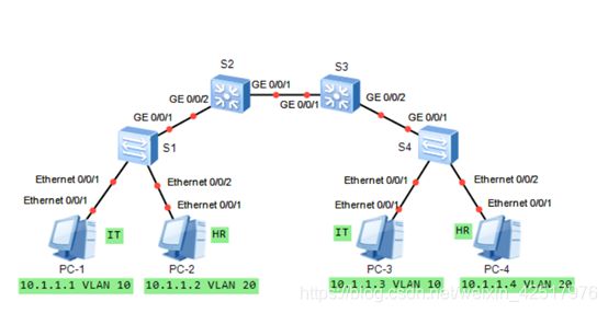
初始化:
S1:
sys
sysname S1
vlan batch 10 20
gvrp
int e0/0/1
port link-type access
port default vlan 10
int e0/0/2
port link-type access
port default vlan 20
int g0/0/1
port link-type trunk
port trunk allow-pass vlan all
gvrp
q

S2:
sys
sysname S2
gvrp
int g0/0/1
port link-type trunk
port trunk allow-pass vlan all
gvrp
int g0/0/2
port link-type trunk
port trunk allow-pass vlan all
gvrp
q

S3:
sys
sysname S3
gvrp
int g0/0/1
port link-type trunk
port trunk allow-pass vlan all
gvrp
int g0/0/2
port link-type trunk
port trunk allow-pass vlan all
gvrp
q

S4:
sys
sysname S4
gvrp
int g0/0/1
port link-type trunk
port trunk allow-pass vlan all
gvrp
q

dis vlan

双向注册
S4:
vlan batch 10 20
int e0/0/1
port link-type access
port default vlan 10
int e0/0/2
port link-type access
port default vlan 20
q

配置GVRP的Fixd模式
S3:
int g0/0/1
gvrp registration fixed
dis vlan

配置GVRP的Forbidden模式
S2:
int g0/0/1
gvrp registration forbidded
dis vlan

个人总结:
1、	交换机本省开启gvrp以及交换机各端口也开启gvrp
连接终端设备的交换机配置VLAN
最终配置
display current-configuration
#
sysname s1
#
vlan batch 10 20
#
gvrp
#
interface Ethernet0/0/1
 port link-type access
 port default vlan 10
#
interface Ethernet0/0/2
 port link-type access
 port default vlan 20
#
interface GigabitEthernet0/0/1
 port link-type trunk
 port trunk allow-pass vlan 2 to 4094
 gvrp
#
Return

display current-configuration
#
sysname s2
#
vlan batch 10 20
#
gvrp
#
interface GigabitEthernet0/0/1
 port link-type trunk
 port trunk allow-pass vlan 2 to 4094
 gvrp
 gvrp registration forbidden
#
interface GigabitEthernet0/0/2
 port link-type trunk
 port trunk allow-pass vlan 2 to 4094
 gvrp
#
Return

 display current-configuration
#
sysname s3
#
vlan batch 10 20
#
gvrp
#
interface GigabitEthernet0/0/1
 port link-type trunk
 port trunk allow-pass vlan 2 to 4094
 gvrp
#
interface GigabitEthernet0/0/2
 port link-type trunk
 port trunk allow-pass vlan 2 to 4094
 gvrp
#
Return

display current-configuration
#
sysname s4
#
vlan batch 10 20
#
gvrp
#
interface Ethernet0/0/1
 port link-type access
 port default vlan 10
#
interface Ethernet0/0/2
 port link-type access
 port default vlan 20
#
interface GigabitEthernet0/0/1
 port link-type trunk
 port trunk allow-pass vlan 2 to 4094
 gvrp
#
Return
个人总结:
①	基本配置以及宣告各端口的类型,配置终端交换机的VLAN,其他的交换机不用配VLAN
②	各自开启本身GVRP以及各自端口的GVRP(除了与终端相连的端口;本身:GVRP,端口的进入端口模式再GVRP)
③	Fixed(不允许动态VLAN,只允许静态)以及Forbiden(不允许动态以及除了VLAN1外的所有VLAN端口的注册)的都要,进入各自端口,然后gvrp registration+模式
10.2 Smart-Link与Monitor-Link
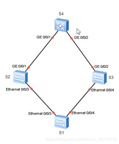
配置Smart Link(下端设备)
S1:
sys
sysname S1
smart-link group 1  //创建smart link 组并开启
smart-link enable
int e0/0/3
stp disable  //关闭stp功能
int e0/0/4
stp disable
q
smart-link group 1
port e0/0/3 master  //创建口3为主接口,口4为备份接口
port e0/0/4 slave
q

dis smart-link group 1

配置回切功能(当一条链路出故障时,会切换到好的那条;当故障的恢复了,不会恢复到原来的,所以配个切换时间。)
S2:
int e0/0/3
shut

S1:
dis smart-link group 1

S2:
int e0/0/3
undo shut

s1:
dis smart-link group 1

smart-link group 1
restore enable 开启
timer wrt 30 切换时间为30秒
dis smart-link group 1

配置Monitor Link
S2:
int g0/0/1
shut

S1:
dis smart-link group 1

S2:
monitor-link group 1
port g0/0/1 uplink
port e0/0/3 downlink

S1:
dis smart-link group 1

S2:
timer recover-time 10
int g0/0/1
undo shut

40秒后
S1:
dis smart-link group 1


最终配置
display current-configuration
#
sysname S1
#
interface Ethernet0/0/3
 stp disable
#
interface Ethernet0/0/4
 stp disable
#
interface NULL0
#
smart-link group 1
 restore enable
 smart-link enable
 port Ethernet0/0/3 master
 port Ethernet0/0/4 slave
 timer wtr 30
#
return

display current-configuration
#
sysname S2
#
monitor-link group 1
 port GigabitEthernet0/0/1 uplink
 port Ethernet0/0/3 downlink 1
 timer recover-time 10
#
Return
个人总结:

### 10.3 配置Eth-Trunk链路聚合

最终配置
display current-configuration
#
sysname S1
#
lacp priority 100
#
interface Eth-Trunk1
 mode lacp-static
 max active-linknumber 2
#
interface GigabitEthernet0/0/1
 eth-trunk 1
 lacp priority 100
#
interface GigabitEthernet0/0/2
 eth-trunk 1
 lacp priority 100
#
interface GigabitEthernet0/0/5
 eth-trunk 1
#
return

display current-configuration
#
sysname S2
#
interface Eth-Trunk1
 mode lacp-static
#
interface GigabitEthernet0/0/1
 eth-trunk 1
#
interface GigabitEthernet0/0/2
 eth-trunk 1
#
interface GigabitEthernet0/0/5
 eth-trunk 1
#
#return
个人总结:
①	 创建聚合链路组(interface Eth-Trunk 1)
②	宣告聚合链路类型(在上条命令下:mode manual load-balance——手工;mode lacp-static——动态)
③	把口加入聚合链路中去(instance+端口 eth-trunk1)
④	设置类型的活动主副机(lacp priority 100-默认为32768),各主机的端口也要配(进入端口,然后lacp priority 100)
⑤	进入聚合链路(interface eth-trunk 1),设置活动接口上限阈值(max active-linknumber 2,这里表明只限两条链路活动),如果有第三条,当活动的挂了,第三条就补上来。
广域网
11.1 WAN接入配置

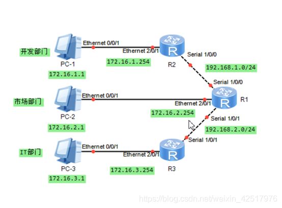
基本配置:
R1:
sys
sysname R1
int e2/0/1
ip add 172.16.2.254 24
int s1/0/0
ip add 192.168.1.2 24
int s1/0/1
ip add 192.168.2.2 24
q
ip route-static 172.16.1.0 255.255.255.0 192.168.1.1


R2:
sys
sysname R2
int e2/0/1
ip add 172.16.1.254 24
int s1/0/0
ip add 192.168.1.1 24
q
ip route-static 0.0.0.0 0.0.0.0 192.168.1.2


R3:
sys
sysname R3
int e2/0/1
ip add 172.16.3.254 24
int s1/0/1
ip add 192.168.2.2 24
q

配置HDLC
R1:
int 1/0/1
link-protocol hdlc

R3:
int s1/0/1
link-protocol hdlc  //开启HDLC

最终配置
display current-configuration

interface Ethernet0/0/1
 ip address 172.16.2.254 255.255.255.0
#
interface Serial1/0/0
 link-protocol ppp
 ip address 192.168.1.2 255.255.255.0
#
interface Serial1/0/1
 link-protocol hdlc
 ip address 192.168.2.2 255.255.255.0
#
dialer-rule
 dialer-rule 1 ip permit

ip route-static 172.16.1.0 255.255.255.0 192.168.1.1
ip route-static 172.16.3.0 255.255.255.0 Serial1/0/1

display current-configuration
interface Ethernet0/0/1
 ip address 172.16.1.254 255.255.255.0
#
interface Serial1/0/0
 link-protocol ppp
 ip address 192.168.1.1 255.255.255.0
#
ip route-static 0.0.0.0 0.0.0.0 192.168.1.2

display current-configuration
interface Ethernet0/0/1
 ip address 172.16.3.254 255.255.255.0
#
interface Serial1/0/1
 link-protocol hdlc
ip address 192.168.2.1 255.255.255.255
#
ip route-static 0.0.0.0 0.0.0.0 Serial1/0/1
11.2 PPP的认证
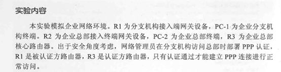
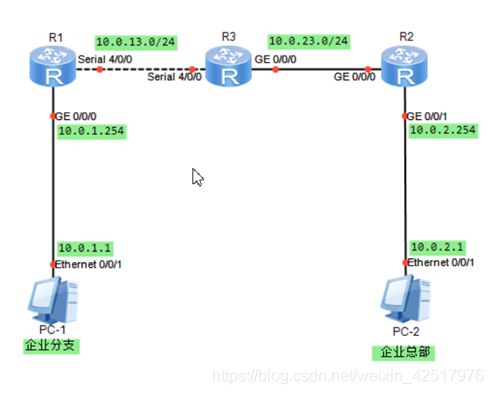
初始化:
R1:
sys
sysname R1
int g0/0/0
ip add 10.0.1.254 24
int s4/0/0
ip add 10.0.13.1 24
q
ospf 1
area 0
network 10.0.1.0 0.0.0.255
network 10.0.13.0 0.0.0.255
q

R2:
sys
sysname R2
int g0/0/1
ip add 10.0.2.254 24
int g0/0/0
ip add 10.0.23.2 24
q
ospf 1
area 0
network 10.0.2.0 0.0.0.255
network 10.0.23.0 0.0.0.255
q

R3:
sys
sysname R3
int g0/0/0
ip add 10.0.23.3 24
int s4/0/0
ip add 10.0.13.3 24
q
ospf 1
area 0
network 10.0.13.0 0.0.0.255
network 10.0.23.0 0.0.0.255
q

配置PPP的PAP认证
R3:
int s4/0/0
ppp authentication-mode pap domain Huawei  //认证采用的域名为Huawei
aaa 进入AAA视图
authentication-scheme huawei_1  //创建认证方案为huawei_1
authentication-mode local  //认证方式为本地连接
q
domain huaweiyu  //创建域
authentication-scheme huawei_1  //创建域的认证方案,必须与认证方案一致
q
aaa
local-user R1@huaweiyu password cipher Huawei  // 域的密码
local-user R1@huaweiyu service-type ppp  //域的认证方式

dis ip interface brief
ping 10.0.13.1

R1:
int s4/0/0
ppp pap local-user R1@huaweiyu password cipher Huawei

dis ip interface brief
ping 10.0.13.3

ping 10.0.2.1

配置PPP的CHAP认证
R3
int s4/0/0
undo ppp authentication-mode

R1:
int s4/0/0
undo ppp pap local-user

R3:
int s4/0/0
ppp authentication-mode chap
aaa
local-user R1 password cipher huawei
local-user R1 service-type ppp
q

R1:
int s4/0/0
ppp chap user R1
ppp chap password huawei

验证:
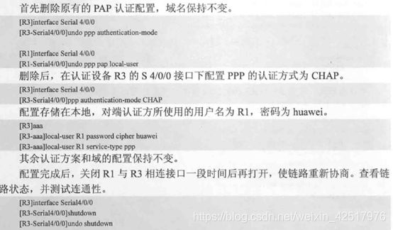
最终配置
display current-configuration
[V200R003C00]
#
sysname R1
#
interface Serial4/0/0
link-protocol ppp
ppp chap user R1
ppp chap password cipher %$%$GMV(*i<^!!:-;{5SNomM,#5_%$%$
ip address 10.0.13.1 255.255.255.0
#
ospf 1
area 0.0.0.0
network 10.0.1.0 0.0.0.255
network 10.0.13.0 0.0.0.255
#
Return

display current-configuration
[V200R003C00]
#
sysname R2
#
interface GigabitEthernet0/0/0
ip address 10.0.23.2 255.255.255.0
#
interface GigabitEthernet0/0/1
ip address 10.0.2.254 255.255.255.0
#
ospf 1
area 0.0.0.0
network 10.0.2.0 0.0.0.255
network 10.0.23.0 0.0.0.255
#
return

display current-configuration
[V200R003C00]
#
sysname R3
#
aaa
local-user R1 password cipher %$%$px4!YD>n
11.3 帧中继基本配置

初始化
R1:
sys
sysname R1
int S1/0/0
ip add 11.1.1.1 24
q

R2:
sys
sysname R2
int s1/0/0
ip add 11.1.1.2 24
q

R3:
sys
sysname R3
int s1/0/0
ip add 22.1.1.3 24
q

动态映射的配置
R1:
int s1/0/0
link-protocol fr
fr inarp

R2:
int s1/0/0
link-protocol fr
undo fr inarp
fr map ip 11.1.1.1 201 broadcast

R1,R2:
dis fr pvc-info
dis fr map-info

R1 ping R2

子接口配置和静态路由
R3:
int s1/0/0
link-protocol fr

dis fr pvc-info
R1 ping R3 通;
R3 ping R1 不通;

R1:
int s1/0/0.1
ip add 22.1.1.1 24
fr dlci 103
最终配置
display current-configuration
[V200R003C00]
#
 sysname R1
#
interface Serial1/0/0
 link-protocol fr
 ip address 10.1.1.1 255.255.255.0
#
interface Serial1/0/0.1
 fr dlci 103
 ip address 20.1.1.1 255.255.255.0
#
interface Serial1/0/1
 link-protocol ppp
#

display current-configuration
[V200R003C00]
#
 sysname R2
#
firewall zone Local
 priority 15
#
interface Serial1/0/0
 link-protocol fr
 undo fr inarp
 fr map ip 10.1.1.1 201 broadcast
 ip address 10.1.1.2 255.255.255.0
#
ip route-static 20.1.1.3 255.255.255.255 10.1.1.1
#
Return

display current-configuration
[V200R003C00]
#
 sysname r3
#
interface Serial1/0/0
 link-protocol fr
 ip address 20.1.1.3 255.255.255.0
#
ip route-static 10.1.1.2 255.255.
#
return
11.4 OSPF在帧中继网络中的配置

最终配置
display current-configuration
[V200R003C00]
#
 sysname R1
#
interface Serial1/0/0
 link-protocol fr
 undo fr inarp
 fr map ip 10.0.123.2 102
 fr map ip 10.0.123.3 103
 ip address 10.0.123.1 255.255.255.0
 ospf dr-priority 100
#
interface LoopBack0
 ip address 10.1.1.1 255.255.255.255
#
ospf 1 router-id 10.1.1.1
 peer 10.0.123.2
 peer 10.0.123.3
 area 0.0.0.0
  network 10.0.123.1 0.0.0.0
  network 10.1.1.1 0.0.0.0

display current-configuration
[V200R003C00]
#
 sysname R2
#
interface Serial1/0/0
 link-protocol fr
 undo fr inarp
 fr map ip 10.0.123.1 201
 fr map ip 10.0.123.3 201
 ip address 10.0.123.2 255.255.255.0
#
interface LoopBack0
 ip address 10.1.2.2 255.255.255.255
#
ospf 1 router-id 10.1.2.2
 peer 10.0.123.1
 area 0.0.0.0
  network 10.0.123.2 0.0.0.0
  network 10.1.2.2 0.0.0.0

display  current-configuration
[V200R003C00]
#
 sysname R3
#
interface Serial1/0/0
 link-protocol fr
 undo fr inarp
 fr map ip 10.0.123.1 301
 fr map ip 10.0.123.2 301
 ip address 10.0.123.3 255.255.255.0
#
interface LoopBack0
 ip address 10.1.3.3 255.255.255.255
#
ospf 1 router-id 10.1.3.3
 peer 10.0.123.1
 area 0.0.0.0
  network 10.0.123.3 0.0.0.0
  network 10.1.3.3 0.0.0.0
DHCP
12.1 配置基于接口地址池的DHCP

基本配置
R1:
sys
sysname R1
int g0/0/0
ip add 192.168.1.254 24
int g0/0/1
ip add 192.168.2.254 24
q
配置端口地址
开启DHCP服务
dhcp enable

基于接口配置DHCP Server
int g0/0/0
dhcp select int
int g0/0/1
dhcp select int

配置基于接口的DHCP Server 的租期和除了那些地址不自动分配以及DNS服务器地址
int g0/0/0
dhcp server day 2
dhcp server excluded-ip-address 192.168.1.1 192.168.1.10
dhcp server dns-list 3.3.3.2

dis ip pool
最终配置
display current-configuration
#
 sysname R1
#
dhcp enable
#
interface GigabitEthernet0/0/0
 ip address 192.168.1.254 255.255.255.0
 dhcp select interface
 dhcp server excluded-ip-address 192.168.1.1 192.168.1.10
 dhcp server lease day 2 hour 0 minute 0
#
interface GigabitEthernet0/0/1
 ip address 192.168.2.254 255.255.255.0
 dhcp select interface
 dhcp server dns-list 8.8.8.8
#
return
12.2 配置基于全局地址池的DHCP

基本配置
R1:
sys
sysname R1
int g0/0/0
ip add 192.168.1.254 24
int g0/0/1
ip add 192.168.2.254 24
q


配置基于全局地址池的DHCP Server
R1:
dhcp enable    //开启DHCP服务
ip pool huawei1  //创建地址池名为huawei1
network 192.168.1.0  //配置地址池的可分配网段
gateway-list 192.168.1.254  //配置地址池的网关

dns-list 8.8.8.3  //DHCP的dns地址
excluded-ip-address 192.168.1.250 192.168.1.253
除了那段地址不做分配外
int g0/0/0
lease day 2  //配置DHCP租赁的时间
dhcp select global  //开启接口的DHCP服务
q

ip pool huawei2
network 192.168.2.0
gateway-list 192.168.2.254
lease day 2
dns-list 8.8.8.3
excluded-ip-address 192.168.2.250 192.168.2.253
int g0/0/1
dhcp select global
q

dis ip pool
最终配置
display current-configuration
#
 sysname R1
#
dhcp enable
#
ip pool huawei1
 gateway-list 192.168.1.254
 network 192.168.1.0 mask 255.255.255.0
 excluded-ip-address 192.168.1.250 192.168.1.253
 lease day 2 hour 0 minute 0
 dns-list 8.8.8.8
#
ip pool huawei2
 gateway-list 192.168.2.254
 network 192.168.2.0 mask 255.255.255.0
 dns-list 8.8.8.8
#
interface GigabitEthernet0/0/0
 ip address 192.168.1.254 255.255.255.0
 dhcp select global
#
interface GigabitEthernet0/0/1
 ip address 192.168.2.254 255.255.255.0
 dhcp select global
#
return
12.3 配置DHCP中继
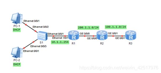
初始化配置:
R1:
sys
sysname R1
int e1/0/1
ip add 10.1.1.254 24
int g0/0/0
ip add 200.1.1.1 24
q
ospf 1
area 0
network 10.1.1.0 0.0.0.255
network 200.1.1.0 0.0.0.255
q
q

R2:
sys
sysname R2
int g0/0/0
ip add 200.1.1.2 24
int g0/0/1
ip add 100.1.1.2 24
q
ospf 1
area 0
network 100.1.1.0 0.0.0.255
network 200.1.1.0 0.0.0.255
q
q

R3:
sys
sysname R3
int g0/0/1
ip add 10.1.1.2 24
q
ospf 1
area 0
network 100.1.1.0 0.0.0.255
q
q

R1,R2,R3: dis ip routing-table

配置DHCP服务器
R3:
dhcp enable
ip pool dhcp-pool
network 10.1.1.0 mask 255.255.255.0
gateway-list 10.1.1.254
int g0/0/1
dhcp select global
q

dis ip pool

配置DHCP中继
法一:
R1:
dhcp enable
int e1/0/1
dhcp select relay
dhcp relay server-ip 100.1.1.1
q

法二:
R1:
dhcp server group dhcp-group
dhcp-server 100.1.1.1
int e1/0/1
dhcp select relay
dhcp relay server-select dhcp-group

最终配置
display current-configuration
#
sysname R1
#
dhcp enable
#
interface Ethernet0/0/1
 ip address 10.1.1.254 255.255.255.0
 dhcp select relay
 dhcp relay server-ip 100.1.1.1
#
interface GigabitEthernet0/0/0
 ip address 200.1.1.1 255.255.255.0
#
ospf 1 router-id 1.1.1.1
 area 0.0.0.0
  network 10.1.1.0 0.0.0.255
  network 200.1.1.0 0.0.0.255
#

display current-configuration
#
sysname r2
#
interface GigabitEthernet0/0/0
 ip address 200.1.1.2 255.255.255.0
#
interface GigabitEthernet0/0/1
 ip address 100.1.1.2 255.255.255.0
#
ospf 1 router-id 2.2.2.2
 area 0.0.0.0
  network 100.1.1.0 0.0.0.255
  network 200.1.1.0 0.0.0.255
#

display current-configuration
#
sysname R3
#
dhcp enable
#
ip pool dhcp-pool
 gateway-list 10.1.1.254
 network 10.1.1.0 mask 255.255.255.0
ospf 1 router-id 3.3.3.3
 area 0.0.0.0
  network 100.1.1.0 0.0.0.255
IPv6
13.1 IPv6基础配置
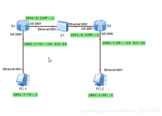
配置IPv6单播地址
R1
sys
sysname R1
ipv6
int g0/0/0
ipv6 enable
ipv6 address auto link-local
dis ipv6 int

R2:
sys
sysname R2
ipv6
int g0/0/0
ipv6 enable
ipv6 address auto link-local
dis ipv6 int

手工配置R1,R2全球单播地址
int g0/0/1
ipv6 enable
ipv6 add 2031:0:130f::1 64
q

int g0/0/1
ipv6 enable
ipv6 add 2031:0:130f::2 64
q

dis ipv6 int g0/0/1
ping ipv6 2031:0:130f::1

用EUI-64方式配置IPv6地址
R1:
int g0/0/0
ipv6 add 2001:3:fd:: 64 eui-64
dis ipv6 int brief

配置IPv6静态路由和默认路由
R1:
ipv6 route-static 2002:3:de:: 64 2031:0:130f::2

R2:
ipv6 route-static :: 0 2031:0:130f::1

测试PC1 ping PC2
ping 2002:3:de::2
最终配置
display current-configuration
[V200R003C00]
#
 sysname R1
#
ipv6
#
interface GigabitEthernet0/0/0
 ipv6 enable
 ipv6 address 2001:3:FD::/64 eui-64
 ipv6 address auto link-local
#
interface GigabitEthernet0/0/1
 ipv6 enable
 ipv6 address 2031:0:130F::1/64
#
ipv6 route-static 2002:3:DE:: 64 2031:0:130F::2

display current-configuration
[V200R003C00]
#
 sysname R2
#
ipv6
#
interface GigabitEthernet0/0/0
 ipv6 enable
 ipv6 address 2002:3:DE::/64 eui-64
 ipv6 address auto link-local
#
interface GigabitEthernet0/0/1
 ipv6 enable
 ipv6 address 2031:0:130F::2/64
#
ipv6 route-static :: 0 2031:0:130F::1
13.2 RIPng基础配置

基本配置
R1:
sys
sysname R1
ipv6
int g0/0/0
ipv6 enable
ipv6 add 2001::1 64
int g0/0/1
ipv6 enable
ipv6 add 2002::1 64
q

R2:
sys
sysname R2
ipv6
int g0/0/0
ipv6 enable
ipv6 add 2001::2 64
int g0/0/1
ipv6 enable
ipv6 add 3001::e 64
q

R3:
sys
sysname R3
ipv6
int g0/0/1
ipv6 enable
ipv6 add 2002::2 64
int g0/0/0
ipv6 enable
ipv6 add 3002::e 64
q

dis ipv6 int brief

配置RIPng
R1,R2,R3:
ripng 1
int g0/0/0
ripng 1 enable
int g0/0/1
ripng 1 enable
q

dis ipv6 routing-table
dis ripng 1 route
最终配置
display current-configuration
[V200R003C00]
#
sysname R1
#
ipv6
#
interface GigabitEthernet0/0/0
ipv6 enable
ipv6 address 2001::1/64
ripng 1 enable
#
interface GigabitEthernet0/0/1
ipv6 enable
ipv6 address 2002::1/64
ripng 1 enable
#
ripng 1
#
Return

display current-configuration
[V200R003C00]
#
sysname R2
#
ipv6
#
interface GigabitEthernet0/0/0
ipv6 enable
ipv6 address 2001::2/64
ripng 1 enable
#
interface GigabitEthernet0/0/1
ipv6 enable
ipv6 address 3001::e/64
ripng 1 enable
#
ripng 1
#
Return

display current-configuration
[V200R003C00]
#
sysname R3
#
ipv6
#
interface GigabitEthernet0/0/0
ipv6 enable
ipv6 address 3002::E/64
ripng 1 enable
#
interface GigabitEthernet0/0/1
ipv6 enable
ipv6 address 2002::2/64
ripng 1 enable
#
ripng 1
#
return
13.3 OSPFv3基础配置

初始化
R1:
sys
sysname R1
ipv6
int g0/0/0
ipv6 enable
ipv6 add 2001::1 64
int g0/0/1
ipv6 enable
ipv6 add 2002::1 64
q
ospfv3 1
router-id 1.1.1.1
q
int g0/0/0
ospfv3 1 area 0
int g0/0/1
ospfv3 1 area 1
q

R2:
sys
sysname R2
ipv6
int g0/0/0
ipv6 enable
ipv6 add 2001::2 64
int g0/0/1
ipv6 enable
ipv6 add 2003::2 64
q
ospfv3 1
router-id 2.2.2.2
q
int g0/0/0
ospfv3 1 area 0
int g0/0/1
ospfv3 1 area 2
q

R3:
sys
sysname R3
ipv6
int g0/0/1
ipv6 enable
ipv6 add 2002::3 64
int e0/0/0
ipv6 enable
ipv6 add 3001::e 64
q
ospfv3 1
router-id 3.3.3.3
q
int  g0/0/1
ospfv3 1 area 1
int e0/0/0
ospfv3 1 area 1
q

R4:
sys
sysname R4
ipv6
int g0/0/1
ipv6 enable
ipv6 add 2003::4 64
int e0/0/0
ipv6 enable
ipv6 add 3002::e 64
q
ospfv3 1
router-id 4.4.4.4
q
int g0/0/1
ospfv3 1 area 2
int e0/0/0
ospfv3 1 area 2
q

R1,R2,R3,R4
dis ospfv3 peer
dis ipv6 routing-table

测试PC1和PC2的连通性
ping 3002::1

验证OSPFv3建立邻居的特性
R1:
int g0/0/0
undo ipv6 add
dis ospfv3 peer

int g0/0/0
ipv6 add 2009::1 64
dis ospfv3 peer

dis ipv6 int g0/0/0
最终配置
display current-configuration
sysname R1
#
ipv6
#
ospfv3 1
 router-id 1.1.1.1
#
interface GigabitEthernet0/0/0
 ipv6 enable
 ipv6 address 2009::1/64
 ipv6 address 2001::1/64
 ospfv3 1 area 0.0.0.0
#
interface GigabitEthernet0/0/1
 ipv6 enable
 ipv6 address 2002::1/64
 ospfv3 1 area 0.0.0.1
#
Return

display current-configuration
sysname R2
#
ipv6
#
ospfv3 1
 router-id 2.2.2.2
#
interface GigabitEthernet0/0/0
 ipv6 enable
 ipv6 address 2001::2/64
 ospfv3 1 area 0.0.0.0
#
interface GigabitEthernet0/0/1
 ipv6 enable
 ipv6 address 2003::2/64
 ospfv3 1 area 0.0.0.2
#
return

display current-configuration
sysname R3
#
ipv6
#
ospfv3 1
 router-id 3.3.3.3
#
interface Ethernet1/0/0
 ipv6 enable
 ipv6 address 3001::E/64
 ospfv3 1 area 0.0.0.1
#
interface GigabitEthernet0/0/1
 ipv6 enable
 ipv6 address 2002::3/64
 ospfv3 1 area 0.0.0.1
#
interface GigabitEthernet0/0/2

display current-configuration
sysname R4
#
ipv6
#
ospfv3 1
 router-id 4.4.4.4
#
interface Ethernet1/0/0
 ipv6 enable
 ipv6 address 3002::E/64
 ospfv3 1 area 0.0.0.2
#
interface GigabitEthernet0/0/1
 ipv6 enable
 ipv6 address 2003::4/64
 ospfv3 1 area 0.0.0.2
其他特性
14.2 SNMP基础配置

最终配置
display current-configuration
#
 sysname Agent
#
 snmp-agent local-engineid 800007DB03000000000000
 snmp-agent community read %$%$A\!Y7j/0sYyg)\SLoP|0,+_@%$%$
 snmp-agent community write %$%$;K6@0->8n;.+guRy3"xU,+_@%$%$
 snmp-agent sys-info contact call admin 020-38370606
 snmp-agent sys-info location Guangzhou China
 snmp-agent sys-info version v3
 snmp-agent target-host trap-hostname adminNMS2 address 10.1.1.2 udp-port 9991 trap-paramsname trapNMS2
 snmp-agent trap source LoopBack0
 snmp-agent trap enable
 snmp-agent trap queue-size 200
snmp-agent trap life 240
 snmp-agent
#
interface GigabitEthernet0/0/0
 ip address 10.1.1.254 255.255.255.0
#
return
14.3 GRE 协议基础配置
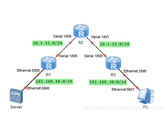
基本配置
R1:
sys
sysname R1
int e2/0/0
ip add 192.168.10.1 24
int s1/0/0
ip add 10.1.12.1 24
q
ip route-static 0.0.0.0 0.0.0.0 10.1.12.2

R2:
sys
sysname R2
int s1/0/0
ip add 10.1.12.2 24
int s1/0/1
ip add 10.1.23.2 24
q

R3:
sys
sysname R3
int e2/0/0
ip add 192.168.20.1 24
int s1/0/0
ip add 10.1.23.1 24
q
ip route-static 0.0.0.0 0.0.0.0 10.1.23.2

PC ping 服务器 不通
//跨越了互联网的2个私网之间默认是无法直接通信的
//这是可以通过GRE协议来实现通信

配置GRE Tunnel
R1:
int tunnel 0/0/0
tunnel-protocol gre
source 10.1.12.1
destination 10.1.23.1
ip add 172.16.1.1 24
q

R3:
int tunel0/0/0
tunnel-protocol gre
source 10.1.23.1
destination 10.1.12.1
ip add 172.16.1.2 24

[R1] ping -a 172.16.1.1 172.16.1.2

最终配置
display current-configuration
sysname R1
#
interface Ethernet2/0/0
 ip address 192.168.10.1 255.255.255.0
#
interface Serial1/0/0
 link-protocol ppp
 ip address 10.1.12.1 255.255.255.0
#
interface NULL0
#
interface Tunnel0/0/0
 ip address 172.16.1.1 255.255.255.0
 tunnel-protocol gre
 source 10.1.12.1
 destination 10.1.23.1
#
rip 1
 version 2
 network 192.168.10.0
 network 172.16.0.0
#
ip route-static 0.0.0.0 0.0.0.0 10.1.12.2
#
Return

display current-configuration
sysname R2
#
interface Serial1/0/0
 link-protocol ppp
 ip address 10.1.12.2 255.255.255.0
#
interface Serial1/0/1
 link-protocol ppp
 ip address 10.1.23.2 255.255.255.0
#
Return

display current-configuration
sysname R3
#
interface Ethernet2/0/0
 ip address 192.168.20.1 255.255.255.0
#
interface Serial1/0/0
 link-protocol ppp
 ip address 10.1.23.1 255.255.255.0
#
interface NULL0
#
interface Tunnel0/0/0
 ip address 172.16.1.2 255.255.255.0
 tunnel-protocol gre
source 10.1.23.1
 destination 10.1.12.1
#
rip 1
 version 2
 network 192.168.20.0
 network 172.16.0.0
#
ip route-static 0.0.0.0 0.0.0.0 10.1.23.2
#
return
14.4 配置NAT

初始化并配置IP地址
R1
sys
sysname R1
int g0/0/1
ip add 172.16.1.254 24
int g0/0/2
ip add 172.17.1.254 24
int g0/0/0
ip add 202.169.10.1 24
q

R2:
sys
sysname R2
int  g0/0/0
ip add 202.169.10.2 24
int loopback 0
ip add 202.169.20.1 24
q

配置静态NAT
R1:
ip route-static 0.0.0.0 0.0.0.0 202.169.10.2
测试PC1 ping R2和R2 ping PC1

int g0/0/0
nat static global 202.169.10.5 inside 172.16.1.1
//写成 nat static global 202.169.20.5 inside 172.16.1.1 就不通

dis nat static
测试PC1 ping R2和R2 ping PC1
R2: ping -a 202.169.20.1 172.16.1.1

2、配置NAT Outbound
R1:
nat addres-group 1 202.169.20.50 202.169.20.60
acl 2001
rule 5 permit 172.17.1.0 0.0.0.255
int g0/0/0
nat outbound 2001 address-group 1 no-pat

dis nat outbound

3、配置NAT Easy-IP
R1:
int g0/0/0
undo nat outbound 2001 address-group 1 nopat
nat outbound 2001

4、配置NAT Server
R1:
int g0/0/0
nat server protocol tcp global 202.169.10.6 ftp inside 172.16.1.3 ftp
q
nat alg ftp enable
display current-configuration
[V200R003C00]
#
 sysname R1
#
acl number 2001
 rule 5 permit source 20.1.1.0 0.0.0.255
#
 nat address-group 1 202.169.10.50 202.169.10.60
#
interface GigabitEthernet0/0/0
 ip address 202.169.10.1 255.255.255.0
 arp-proxy enable
 nat static global 202.169.10.5 inside 10.1.1.1 netmask 255.255.255.255
 nat outbound 2001 address-group 1 no-pat
#
interface GigabitEthernet0/0/1
 ip address 10.1.1.254 255.255.255.0
#
interface GigabitEthernet0/0/2
 ip address 20.1.1.254 255.255.255.0
#
interface NULL0
#
ip route-static 0.0.0.0 0.0.0.0 202.169.10.2
#
Return

display current-configuration
[V200R003C00]
#
 sysname R2
#
 snmp-agent local-engineid 800007DB03000000000000
 snmp-agent
#
interface GigabitEthernet0/0/0
 ip address 202.169.10.2 255.255.255.0
#
interface LoopBack0
 ip address 202.169.20.1 255.255.255.0
#
return
目前就先汇总到这里吧,后续……