一天上手Aurora 8B/10B IP核(5)----从Framing接口的官方例程学起
文章目录
写在前面
1、IP核定制与官方例程的生成
1.1、第一页配置:物理层以及链路层信息选择
1.2、第二页配置:对应GT收发器的物理位置选择
1.3、第三页配置:共享逻辑的位置
1.4、官方例程Example Design的生成
2、官方例程解析
2.1、官方例程的组成
2.2、Support模块(IP核例化核心模块)
2.3、数据生成模块(发送)
2.3.1、端口
2.3.2、等待初始化
2.3.3、LFSR的使用
2.3.4、状态机实现帧发送
2.3.5、仿真与分析
2.4、数据校验模块(接收)
2.4.1、端口与打拍
2.4.2、复位
2.4.3、数据有效性判断
2.4.4、数据的再处理(译码)
2.4.5、LFSR数据生成
2.4.6、数据校验以及错误标志
2.4.7、仿真结果
3、整体仿真
4、总结
写在前面
Xilinx的技术生态做的非常好,基本上所有常用的IP核都有官方例程(example design)供开发者学习,咱不用白不用,今儿咱就一起白嫖他一手----从官方例程开始学习如何具体使用这个IP核。
系列汇总:一天上手Aurora 8B/10B IP核----汇总篇(直达链接)
1、IP核定制与官方例程的生成
首先新建一个工程,这个工程什么除了生成Aurora 8B/10B IP核以外什么也不做。IP核的定制过程如下。
1.1、第一页配置:物理层以及链路层信息选择
物理层Physical Layer:
- Lane Width:链路位宽,可选项2或者4,单位Bytes(这里我们为了将用户时钟降下来方便后续做时钟约束,选择4bytes)
- Line Rate:线速率,范围0.5~6.25Gbps,这个根据项目需求来就行,选择3.125Gbps
- GT Refclk:串行收发器GT的参考时钟,根据板卡实际情况来,我们这里选择125M
- INIT clk:初始化时钟,在GT复位时,user_clk是停止工作的,推荐INIT CLK时钟频率低于GT参考时钟,直接选择默认50M
- DRP clk:动态重配置时钟,该功能用的不多,直接按默认50M来就是的
链路层Link Layer:
- Dataflow Mode:数据流模式,可选全双工/ 只接收/ 只发送,我们这里选择全双工模式
- Interface:Framing/streaming可选。本文为Framing接口
- Flow Control:流控,暂时不搞这么复杂,不选
- Back Channel:只有在单工模式才能选择(sidebands/timer 可选)
- Scrambler/Descrambler :绕码/解绕,这里不选择
- Little Endian Support :勾选小端模式,小段模式对应[31:0]这种书写习惯,大端模式对应的是[0:31]这种书写习惯
调试和控制----Debug And Control:
提供了诸如ILA和VIO等调试IO核和其他一些状态指示位来对IP的运行状态进行监控,我们为了测试方便,这类调试接口暂时不选取。
1.2、第二页配置:对应GT收发器的物理位置选择
这里根据自己的FPGA芯片上的GT实际情况选择就行,我们仅仿真测试,就随便选取一条通道:
1.3、第三页配置:共享逻辑的位置
例如时钟以及复位等逻辑,是在核内还是在例子工程内(大多数IP核Xilinx都会提供例程供参考)。推荐将共享逻辑设置在官方例程内,这样我们后续对IP核的使用就可以直接在官方例程的基础上进行一点小修改就行了。
1.4、官方例程Example Design的生成
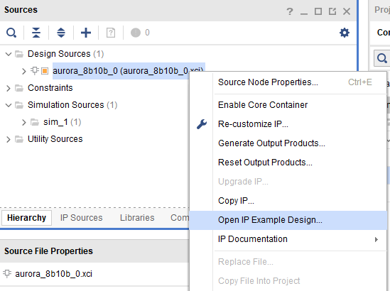
将IP核定制好并综合后,就可以生成官方例程Example Design了:
2、官方例程解析
对官方例程的解析主要参考生成源码以及《PG046:Aurora 8B/10B v11.1 LogiCORE IP Product Guide》。通过上述资料,我们可以掌握IP核的使用方法并了解官方例程的大致组成。
2.1、官方例程的组成
我们首先看下生成例程文件的逻辑层级排列:
设计文件的层次这样看不是很明显,我们调出结构框图再来看看:
这样基本能看明白大概了:
- support模块:核心模块,包含了对IP、GT等的例化处理等一系列操作;后续在我们的应用中此部分不需要修改
- frame_gen:数据生成模块,采用LFSR的方式生成伪随机序列;后续在我们的应用中此部分可替换成我们的数据输入模块(建议加入FIFO,这样代码的复用性更佳)
- frame_check:数据检验模块,对接受的数据进行检验以验证传输的正确性;后续在我们的应用中此部分可替换成我们的数据检查模块或者删除
- LL_AXI:LL总线转AXI总线(据说该例程原本的接口是LL接口,后面Xilinx为了推广AXI总线,所以本例程直接在原来代码的基础上增加了总线转换模块)
- AXI_LL:AXI总线转LL总线,原因同上
仿真部分的内容根据层级就很容易理解--调用了两次例程。根据Xilinx一贯的尿性,很容易猜出来这又是要进行环回测试。实际上从手册中也可以窥见一二:
- Testbench例化了两个例程
- 例程1生成数据后经Aurora发给了例程2的检测模块,并将结果反馈给Testbench
- 例程2生成数据后经Aurora发给了例程1的检测模块,并将结果反馈给Testbench
2.2、Support模块(IP核例化核心模块)
废话不多说,先来看下Support模块的组成:
从组成就不难看出,Support模块最主要的功能是例化aurora IP核并将时钟、复位等信号统统一起打包。所以我们不需要对Support模块的内部构造进行详细了解,直接看看其对外接口就差不多可以拿来用了。Support模块下的子模块:
- clock_module:时钟处理生成模块
- support_reset_logic_i:复位逻辑生成模块
- gt_common_support:与GT收发器相关的时钟生成其其他
- Aurora IP核模块
2.3、数据生成模块(发送)
上面说了只要将数据生成模块替换成我们自己的文件就可以实现对官方例程的二次创作,从而完成对Aurora IP的利用了。那么我们自然需要对其源码好好探究一番了。完整代码如下:
`timescale 1 ns / 1 ps
`define DLY #1

module aurora_8b10b_0_FRAME_GEN
(
    // User Interface
    TX_D,
    TX_REM,
    TX_SOF_N,
    TX_EOF_N,
    TX_SRC_RDY_N,
    TX_DST_RDY_N,
    // System Interface
    USER_CLK,
    RESET,
    CHANNEL_UP
);
//*****************************Parameter Declarations****************************

//***********************************Port Declarations*******************************
// User Interface
output  [0:31]     TX_D;
output  [0:1]      TX_REM;
output             TX_SOF_N;
output             TX_EOF_N;
output             TX_SRC_RDY_N;
input              TX_DST_RDY_N;
// System Interface
input              USER_CLK;
input              RESET;
input              CHANNEL_UP;
//***************************External Register Declarations***************************
reg                TX_SRC_RDY_N;
reg                TX_SOF_N;
reg                TX_EOF_N;
//***************************Internal Register Declarations***************************
reg     [0:15]     data_lfsr_r;
reg     [0:7]      frame_size_r;
reg     [0:7]      bytes_sent_r;
reg     [0:3]      ifg_size_r;
//State registers for one-hot state machine
reg                idle_r;
reg                single_cycle_frame_r;
reg                sof_r;
reg                data_cycle_r;
reg                eof_r;
wire               reset_c;
//*********************************Wire Declarations**********************************
wire               ifg_done_c;
//Next state signals for one-hot state machine
wire               next_idle_c;
wire               next_single_cycle_frame_c;
wire               next_sof_c;
wire               next_data_cycle_c;
wire               next_eof_c;
wire       		   dly_data_xfer;
reg [4:0]  		   channel_up_cnt;
//*********************************Main Body of Code**********************************
  always @ (posedge USER_CLK)
  begin
    if(RESET)
        channel_up_cnt <= `DLY 5'd0;
    else if(CHANNEL_UP)
      if(&channel_up_cnt)
        channel_up_cnt <= `DLY channel_up_cnt;
      else
        channel_up_cnt <= `DLY channel_up_cnt + 1'b1;
    else
      channel_up_cnt <= `DLY 5'd0;
  end

  assign dly_data_xfer = (&channel_up_cnt);

  //Generate RESET signal when Aurora channel is not ready
  assign reset_c = RESET || !dly_data_xfer;

    //______________________________ Transmit Data  __________________________________
    //Generate random data using XNOR feedback LFSR
    always @(posedge USER_CLK)
        if(reset_c)
        begin
            data_lfsr_r          <=  `DLY    16'hABCD;  //random seed value
        end
        else if(!TX_DST_RDY_N && !idle_r)
        begin
            data_lfsr_r          <=  `DLY    {!{data_lfsr_r[3]^data_lfsr_r[12]^data_lfsr_r[14]^data_lfsr_r[15]},
                                data_lfsr_r[0:14]};
        end

    //Connect TX_D to the DATA LFSR
    assign  TX_D    =   {2{data_lfsr_r}};
    //Tie DATA LFSR to REM to generate random words
    assign  TX_REM  = data_lfsr_r[0:1];
    //Use a counter to determine the size of the next frame to send
    always @(posedge USER_CLK)
        if(reset_c)
            frame_size_r    <=  `DLY    8'h00;
        else if(single_cycle_frame_r || eof_r)
            frame_size_r    <=  `DLY    frame_size_r + 1;

    //Use a second counter to determine how many bytes of the frame have already been sent
    always @(posedge USER_CLK)
        if(reset_c)
            bytes_sent_r    <=  `DLY    8'h00;
        else if(sof_r)
            bytes_sent_r    <=  `DLY    8'h01;
        else if(!TX_DST_RDY_N && !idle_r)
            bytes_sent_r    <=  `DLY    bytes_sent_r + 1;

    //Use a freerunning counter to determine the IFG
    always @(posedge USER_CLK)
        if(reset_c)
            ifg_size_r      <=  `DLY    4'h0;
        else
            ifg_size_r      <=  `DLY    ifg_size_r + 1;
    //IFG is done when ifg_size register is 0
    assign  ifg_done_c  =   (ifg_size_r == 4'h0);

    //_____________________________ Framing State machine______________________________
    //Use a state machine to determine whether to start a frame, end a frame, send
    //data or send nothing
    //State registers for 1-hot state machine
    always @(posedge USER_CLK)
        if(reset_c)
        begin
            idle_r                  <=  `DLY    1'b1;
            single_cycle_frame_r    <=  `DLY    1'b0;
            sof_r                   <=  `DLY    1'b0;
            data_cycle_r            <=  `DLY    1'b0;
            eof_r                   <=  `DLY    1'b0;
        end
        else if(!TX_DST_RDY_N)
        begin
            idle_r                  <=  `DLY    next_idle_c;
            single_cycle_frame_r    <=  `DLY    next_single_cycle_frame_c;
            sof_r                   <=  `DLY    next_sof_c;
            data_cycle_r            <=  `DLY    next_data_cycle_c;
            eof_r                   <=  `DLY    next_eof_c;
        end

    //Nextstate logic for 1-hot state machine
    assign  next_idle_c                 =   !ifg_done_c &&
                                            (single_cycle_frame_r || eof_r || idle_r);

    assign  next_single_cycle_frame_c   =   (ifg_done_c && (frame_size_r == 0)) &&
                                            (idle_r || single_cycle_frame_r || eof_r);

    assign  next_sof_c                  =   (ifg_done_c && (frame_size_r != 0)) &&
                                            (idle_r || single_cycle_frame_r || eof_r);

    assign  next_data_cycle_c           =   (frame_size_r != bytes_sent_r) &&
                                            (sof_r || data_cycle_r);

    assign  next_eof_c                  =   (frame_size_r == bytes_sent_r) &&
                                            (sof_r || data_cycle_r);

    //Output logic for 1-hot state machine
    always @(posedge USER_CLK)
        if(reset_c)
        begin
            TX_SOF_N        <=  `DLY    1'b1;
            TX_EOF_N        <=  `DLY    1'b1;
            TX_SRC_RDY_N    <=  `DLY    1'b1;
        end
        else if(!TX_DST_RDY_N)
        begin
            TX_SOF_N        <=  `DLY    !(sof_r || single_cycle_frame_r);
            TX_EOF_N        <=  `DLY    !(eof_r || single_cycle_frame_r);
            TX_SRC_RDY_N    <=  `DLY    idle_r;
        end

endmodule
代码不多,咱直接一段一段的拆。
2.3.1、端口
先来看看官方文档的标准Framing接口,然后再对比代码。
// User Interface
output  [0:31]     TX_D;			//要发送的数据
output  [0:1]      TX_REM;			//随机字
output             TX_SOF_N;		//帧头指示,低有效
output             TX_EOF_N;		//帧尾指示,低有效
output             TX_SRC_RDY_N;	//tvalid
input              TX_DST_RDY_N;	//tready
// System Interface
input              USER_CLK;		//用户时钟
input              RESET; 			//复位
input              CHANNEL_UP;		//通道有效信号,高有效
2.3.2、等待初始化
//CHANNEL_UP起来后,channel_up_cnt计数16个时钟周期
  always @ (posedge USER_CLK)
  begin
    if(RESET)
        channel_up_cnt <= `DLY 5'd0;
    else if(CHANNEL_UP)
      if(&channel_up_cnt)
        channel_up_cnt <= `DLY channel_up_cnt;
      else
        channel_up_cnt <= `DLY channel_up_cnt + 1'b1;
    else
      channel_up_cnt <= `DLY 5'd0;
  end

  assign dly_data_xfer = (&channel_up_cnt);		//channel_up_cnt计数16个时钟周期满后,拉高dly_data_xfer

  //Generate RESET signal when Aurora channel is not ready
  assign reset_c = RESET || !dly_data_xfer;		//
如果CHANNEL_UP还没有起来,那么channel_up_cnt将为全0,而dly_data_xfer为0,所以语句assign reset_c = RESET || !dly_data_xfer恒成立,reset_c恒为1,所以一直处于复位状态。
当CHANNEL_UP起来后,channel_up_cnt需要一定的时间才能计数到5‘b11111,然后dly_data_xfer为1,所以此时assign reset_c = RESET || !dly_data_xfer等价于assign reset_c = RESET,即RESET控制reset_c信号。而RESET一般在CHANNEL_UP起来后就处于无效复位状态了,所以此时通道进入正常工作模式。
2.3.3、LFSR的使用
    //Generate random data using XNOR feedback LFSR
    always @(posedge USER_CLK)
        if(reset_c)
        begin
            data_lfsr_r          <=  `DLY    16'hABCD;  //random seed value
        end
        else if(!TX_DST_RDY_N && !idle_r)
        begin
            data_lfsr_r          <=  `DLY    {!{data_lfsr_r[3]^data_lfsr_r[12]^data_lfsr_r[14]^data_lfsr_r[15]},
                                data_lfsr_r[0:14]};
        end

    //Connect TX_D to the DATA LFSR
    assign  TX_D    =   {2{data_lfsr_r}};
    //Tie DATA LFSR to REM to generate random words
    assign  TX_REM  = data_lfsr_r[0:1];
关于LFSR可参考:FPGA实现的线性反馈移位寄存器LFSR
此时载入的种子为16'hABCD。
2.3.4、状态机实现帧发送
这个模块用了一个状态机来描述发送过程。需要注意的是状态机的写法跟我们平常接触的三段式状态机有一些区别,所以看起来有点别扭,比如它的5个状态如下:
    //Use a state machine to determine whether to start a frame, end a frame, send
    //data or send nothing
    //State registers for 1-hot state machine
    always @(posedge USER_CLK)
        if(reset_c)
        begin
            idle_r                  <=  `DLY    1'b1;
            single_cycle_frame_r    <=  `DLY    1'b0;
            sof_r                   <=  `DLY    1'b0;
            data_cycle_r            <=  `DLY    1'b0;
            eof_r                   <=  `DLY    1'b0;
        end
        else if(!TX_DST_RDY_N)
        begin
            idle_r                  <=  `DLY    next_idle_c;
            single_cycle_frame_r    <=  `DLY    next_single_cycle_frame_c;
            sof_r                   <=  `DLY    next_sof_c;
            data_cycle_r            <=  `DLY    next_data_cycle_c;
            eof_r                   <=  `DLY    next_eof_c;
然后状态转移条件如下:
    //Nextstate logic for 1-hot state machine
    assign  next_idle_c                 =   !ifg_done_c &&
                                            (single_cycle_frame_r || eof_r || idle_r);

    assign  next_single_cycle_frame_c   =   (ifg_done_c && (frame_size_r == 0)) &&
                                            (idle_r || single_cycle_frame_r || eof_r);

    assign  next_sof_c                  =   (ifg_done_c && (frame_size_r != 0)) &&
                                            (idle_r || single_cycle_frame_r || eof_r);

    assign  next_data_cycle_c           =   (frame_size_r != bytes_sent_r) &&
                                            (sof_r || data_cycle_r);

    assign  next_eof_c                  =   (frame_size_r == bytes_sent_r) &&
                                            (sof_r || data_cycle_r);
其中有一些参数需要了解才能掌握状态机的跳转:
(1)ifg_done_c
    //Use a freerunning counter to determine the IFG
    always @(posedge USER_CLK)
        if(reset_c)
            ifg_size_r      <=  `DLY    4'h0;
        else
            ifg_size_r      <=  `DLY    ifg_size_r + 1;
    //IFG is done when ifg_size register is 0
    assign  ifg_done_c  =   (ifg_size_r == 4'h0);
构建了一个一直在从00000~11111计数的计数器,每当计数器值为0即拉高ifg_done_c
(2) frame_size_r
    //Use a counter to determine the size of the next frame to send
    always @(posedge USER_CLK)
        if(reset_c)
            frame_size_r    <=  `DLY    8'h00;
        else if(single_cycle_frame_r || eof_r)
            frame_size_r    <=  `DLY    frame_size_r + 1;
frame_size_r是一帧数据大小的计数器,初始值为0,当发送第一帧或者发送完一帧后累加1,也就说后,第一次发送长度为1的一帧数据,第二次则发送长度为2的一帧数据,以此类推。
(3)bytes_sent_r
    //Use a second counter to determine how many bytes of the frame have already been sent
    always @(posedge USER_CLK)
        if(reset_c)
            bytes_sent_r    <=  `DLY    8'h00;
        else if(sof_r)
            bytes_sent_r    <=  `DLY    8'h01;
        else if(!TX_DST_RDY_N && !idle_r)
            bytes_sent_r    <=  `DLY    bytes_sent_r + 1;
bytes_sent_r是用来计算当前一帧数据中以及有多少个BYTE的数据被发送出去了。
(4)输出
    //Output logic for 1-hot state machine
    always @(posedge USER_CLK)
        if(reset_c)
        begin
            TX_SOF_N        <=  `DLY    1'b1;
            TX_EOF_N        <=  `DLY    1'b1;
            TX_SRC_RDY_N    <=  `DLY    1'b1;
        end
        else if(!TX_DST_RDY_N)
        begin
            TX_SOF_N        <=  `DLY    !(sof_r || single_cycle_frame_r);
            TX_EOF_N        <=  `DLY    !(eof_r || single_cycle_frame_r);
            TX_SRC_RDY_N    <=  `DLY    idle_r;
        end
2.3.5、仿真与分析
状态转移图给你们画出来了:
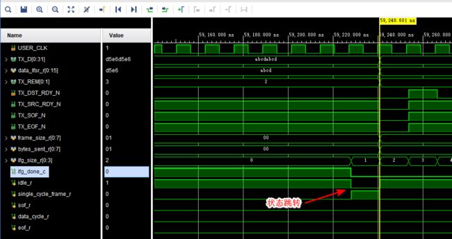
有了这些条件后,可以根据仿真推断整个状态机是如何运转的了:
(1)上电复位
上电复位,等待IP核初始化完成,并在其初始化完成后继续延迟一段时间。
(2)初始状态
上电复位成功后,状态机处于状态idle_r,此时帧大小frame_size_r为0,计数器ifg_size_r为0,所以ifg_done_c为1,状态会跳转到single_cycle_frame_r
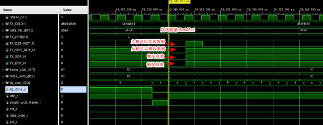
(3)发送一帧数据(单个数据)
帧大小frame_size_r+1,此时不满足任何条件,保持在该状态;此时发送单帧数据
(4)发送一帧数据(多个数据)
计数器ifg_size_r计数到11111后重新跳转到00000,ifg_done_c为1,且此时帧大小frame_size_r为1(非0),所以状态会跳转到sof
(5)发送一帧数据(多个数据)
此后,每次发送的一帧数据都会比前一帧都1个BYTE,直到仿真结束。
(6)总结
所以,发送模块要实现的功能实际上就是:先发送1个BYTE的一帧数据,间隔一段时间后发送2个BYTE的一帧数据,再间隔一段时间后发生3个BYTE的一帧数据,以此类推······发送的数据是使用LFSR来生成的伪随机数列。
2.4、数据校验模块(接收)
既然有发送模块,那肯定也有接收(校验)模块啦,不然我怎么知道你发送的正确不正确呢?
`timescale 1 ns / 1 ps
`define DLY #1

module aurora_8b10b_0_FRAME_CHECK
(
    // User Interface
    RX_D,
    RX_REM,
    RX_SOF_N,
    RX_EOF_N,
    RX_SRC_RDY_N,
    // System Interface
    USER_CLK,
    RESET,
    CHANNEL_UP,
    ERR_COUNT
);
//***********************************Port Declarations*******************************
// User Interface
input   [0:31]     RX_D;
input   [0:1]      RX_REM;
input              RX_SOF_N;
input              RX_EOF_N;
input              RX_SRC_RDY_N;
// System Interface
input              USER_CLK;
input              RESET;
input              CHANNEL_UP;
output  [0:7]      ERR_COUNT;
//***************************Internal Register Declarations***************************
// Slack registers
reg   [0:31]     	RX_D_SLACK;
reg   [0:1]      	RX_REM_1SLACK;
reg   [0:1]      	RX_REM_2SLACK;
reg              	RX_SOF_N_SLACK;
reg              	RX_EOF_N_SLACK;
reg              	RX_SRC_RDY_N_SLACK;
reg     [0:8]      	err_count_r = 9'd0;
reg                	data_in_frame_r;
reg                	data_valid_r;
reg     [0:31]     	RX_D_R;
reg     [0:31]     	pdu_cmp_data_r;
// RX Data registers
reg     [0:15]      data_lfsr_r;
//*********************************Wire Declarations**********************************
wire               reset_c;
wire    [0:31]     data_lfsr_concat_w;
wire               data_valid_c;
wire               data_in_frame_c;
wire               data_err_detected_c;
reg                data_err_detected_r;
//*********************************Main Body of Code**********************************
//Generate RESET signal when Aurora channel is not ready
  assign reset_c = RESET;

// SLACK registers
always @ (posedge USER_CLK)
begin
  RX_D_SLACK          <= `DLY RX_D;
  RX_SRC_RDY_N_SLACK  <= `DLY RX_SRC_RDY_N;
  RX_REM_1SLACK       <= `DLY RX_REM;
  RX_REM_2SLACK       <= `DLY RX_REM;
  RX_SOF_N_SLACK      <= `DLY RX_SOF_N;
  RX_EOF_N_SLACK      <= `DLY RX_EOF_N;
end

    //______________________________ Capture incoming data ___________________________
    //Data is valid when RX_SRC_RDY_N is asserted and data is arriving within a frame
    assign  data_valid_c    =   data_in_frame_c && !RX_SRC_RDY_N_SLACK;

    //Data is in a frame if it is a single cycle frame or a multi_cycle frame has started
    assign  data_in_frame_c  =   data_in_frame_r  ||  (!RX_SRC_RDY_N_SLACK && !RX_SOF_N_SLACK);

    //RX Data in the pdu_cmp_data_r register is valid
    //only if it was valid when captured and had no error
    always @(posedge USER_CLK)
        if(reset_c)
           data_valid_r    <=  `DLY    1'b0;
        else if(CHANNEL_UP)
           data_valid_r    <=  `DLY    data_valid_c && !data_err_detected_c;
        else
           data_valid_r    <=  `DLY    1'b0;

    //Start a multicycle frame when a frame starts without ending on the same cycle. End
    //the frame when an EOF is detected
    always @(posedge USER_CLK)
        if(reset_c)
            data_in_frame_r  <=  `DLY    1'b0;
        else if(CHANNEL_UP)
        begin
          if(!data_in_frame_r && !RX_SOF_N_SLACK && !RX_SRC_RDY_N_SLACK && RX_EOF_N_SLACK)	//1帧开始
            data_in_frame_r  <=  `DLY    1'b1;
          else if(data_in_frame_r && !RX_SRC_RDY_N_SLACK && !RX_EOF_N_SLACK)				//1帧结束
            data_in_frame_r  <=  `DLY    1'b0;
        end

    //Register and decode the RX_D data with RX_REM bus
    always @ (posedge USER_CLK)
    begin
      if((!RX_EOF_N_SLACK) && (!RX_SRC_RDY_N_SLACK))
      begin
        case(RX_REM_1SLACK)
          2'd0 : RX_D_R <=  `DLY {RX_D_SLACK[0:7], 24'b0};
          2'd1 : RX_D_R <=  `DLY {RX_D_SLACK[0:15], 16'b0};
          2'd2 : RX_D_R <=  `DLY {RX_D_SLACK[0:23], 8'b0};
          2'd3 : RX_D_R <=  `DLY RX_D_SLACK;
          default : RX_D_R  <=  `DLY RX_D_SLACK;
	endcase
      end
      else if(!RX_SRC_RDY_N_SLACK)
        RX_D_R          <=  `DLY    RX_D_SLACK;
    end

    //Calculate the expected frame data
    always @ (posedge USER_CLK)
    begin
      if(reset_c)
        pdu_cmp_data_r <= `DLY {2{16'hD5E6}};
      else if(CHANNEL_UP)
      begin
        if(data_valid_c && !RX_EOF_N_SLACK)
        begin
          case(RX_REM_2SLACK)
            2'd0 : pdu_cmp_data_r <=  `DLY {data_lfsr_concat_w[0:7], 24'b0};
            2'd1 : pdu_cmp_data_r <=  `DLY {data_lfsr_concat_w[0:15], 16'b0};
            2'd2 : pdu_cmp_data_r <=  `DLY {data_lfsr_concat_w[0:23], 8'b0};
            2'd3 : pdu_cmp_data_r <=  `DLY data_lfsr_concat_w;
            default : pdu_cmp_data_r <=  `DLY data_lfsr_concat_w;
	  endcase
        end
        else if(data_valid_c)
          pdu_cmp_data_r <=  `DLY data_lfsr_concat_w;
        end
      end

    //generate expected RX_D using LFSR
    always @(posedge USER_CLK)
        if(reset_c)
        begin
            data_lfsr_r          <=  `DLY    16'hD5E6;  //random seed value
        end
        else if(CHANNEL_UP)
        begin
          if(data_valid_c)
           data_lfsr_r          <=  `DLY    {!{data_lfsr_r[3]^data_lfsr_r[12]^data_lfsr_r[14]^data_lfsr_r[15]},
                                data_lfsr_r[0:14]};
        end
        else
        begin
           data_lfsr_r          <=  `DLY    16'hD5E6;  //random seed value
        end

    assign data_lfsr_concat_w = {2{data_lfsr_r}};

    //___________________________ Check incoming data for errors __________________________
    //An error is detected when LFSR generated RX data from the pdu_cmp_data_r register,
    //does not match valid data from the RX_D port
    assign  data_err_detected_c    = (data_valid_r && (RX_D_R != pdu_cmp_data_r));

    //We register the data_err_detected_c signal for use with the error counter logic
    always @(posedge USER_CLK)
      data_err_detected_r    <=  `DLY    data_err_detected_c;

    //Compare the incoming data with calculated expected data.
    //Increment the ERROR COUNTER if mismatch occurs.
    //Stop the ERROR COUNTER once it reaches its max value (i.e. 255)
    always @(posedge USER_CLK)
        if(CHANNEL_UP)
        begin
          if(&err_count_r)
            err_count_r       <=  `DLY    err_count_r;
          else if(data_err_detected_r)
            err_count_r       <=  `DLY    err_count_r + 1;
        end
	else
        begin
          err_count_r       <=  `DLY    9'd0;
	end

    //Here we connect the lower 8 bits of the count (the MSbit is used only to check when the counter reaches
    //max value) to the module output
    assign  ERR_COUNT =   err_count_r[1:8];

endmodule
2.4.1、端口与寄存
// User Interface
input   [0:31]     RX_D;
input   [0:1]      RX_REM;
input              RX_SOF_N;
input              RX_EOF_N;
input              RX_SRC_RDY_N;
// System Interface
input              USER_CLK;
input              RESET;
input              CHANNEL_UP;
output  [0:7]      ERR_COUNT;


// SLACK registers
always @ (posedge USER_CLK)
begin
  RX_D_SLACK          <= `DLY RX_D;
  RX_SRC_RDY_N_SLACK  <= `DLY RX_SRC_RDY_N;
  RX_REM_1SLACK       <= `DLY RX_REM;
  RX_REM_2SLACK       <= `DLY RX_REM;
  RX_SOF_N_SLACK      <= `DLY RX_SOF_N;
  RX_EOF_N_SLACK      <= `DLY RX_EOF_N;
end
端口信号基本上是与发送模块一一对应的,只不过多了一个错误计数输出。然后所有的输入信号都寄存了一拍,以改善时序。
2.4.2、复位
//Generate RESET signal when Aurora channel is not ready
  assign reset_c = RESET;
复位直接用就行,不存在初始化不稳定的问题。因为当发送端能正常发送数据过来,说明数据链路已经成功建立了。
2.4.3、数据有效性判断
    //Data is valid when RX_SRC_RDY_N is asserted and data is arriving within a frame
    assign  data_valid_c    =   data_in_frame_c && !RX_SRC_RDY_N_SLACK;

    //Data is in a frame if it is a single cycle frame or a multi_cycle frame has started
    assign  data_in_frame_c  =   data_in_frame_r  ||  (!RX_SRC_RDY_N_SLACK && !RX_SOF_N_SLACK);

    //RX Data in the pdu_cmp_data_r register is valid
    //only if it was valid when captured and had no error
    always @(posedge USER_CLK)
        if(reset_c)
           data_valid_r    <=  `DLY    1'b0;
        else if(CHANNEL_UP)
           data_valid_r    <=  `DLY    data_valid_c && !data_err_detected_c;
        else
           data_valid_r    <=  `DLY    1'b0;

    //Start a multicycle frame when a frame starts without ending on the same cycle. End
    //the frame when an EOF is detected
    always @(posedge USER_CLK)
        if(reset_c)
            data_in_frame_r  <=  `DLY    1'b0;
        else if(CHANNEL_UP)
        begin
          if(!data_in_frame_r && !RX_SOF_N_SLACK && !RX_SRC_RDY_N_SLACK && RX_EOF_N_SLACK)	//1帧开始
            data_in_frame_r  <=  `DLY    1'b1;
          else if(data_in_frame_r && !RX_SRC_RDY_N_SLACK && !RX_EOF_N_SLACK)				//1帧结束
            data_in_frame_r  <=  `DLY    1'b0;
        end
根据帧头、帧尾信号来构建表示一帧数据有效的信号。
2.4.4、数据的再处理(译码)
    //Register and decode the RX_D data with RX_REM bus
    always @ (posedge USER_CLK)
    begin
      if((!RX_EOF_N_SLACK) && (!RX_SRC_RDY_N_SLACK))
      begin
        case(RX_REM_1SLACK)
          2'd0 : RX_D_R <=  `DLY {RX_D_SLACK[0:7], 24'b0};
          2'd1 : RX_D_R <=  `DLY {RX_D_SLACK[0:15], 16'b0};
          2'd2 : RX_D_R <=  `DLY {RX_D_SLACK[0:23], 8'b0};
          2'd3 : RX_D_R <=  `DLY RX_D_SLACK;
          default : RX_D_R  <=  `DLY RX_D_SLACK;
	endcase
      end
      else if(!RX_SRC_RDY_N_SLACK)
        RX_D_R          <=  `DLY    RX_D_SLACK;
    end
根据RX_REM_1SLACK信号对接收到的数据再处理(类似译码过程),能提高数据的随机性。RX_REM_1SLACK信号是RX_REM被寄存后的信号,而RX_REM信号是一个发送端发送的2bit随机数。
2.4.5、LFSR数据生成
    //Calculate the expected frame data
    always @ (posedge USER_CLK)
    begin
      if(reset_c)
        pdu_cmp_data_r <= `DLY {2{16'hD5E6}};
      else if(CHANNEL_UP)
      begin
        if(data_valid_c && !RX_EOF_N_SLACK)
        begin
          case(RX_REM_2SLACK)
            2'd0 : pdu_cmp_data_r <=  `DLY {data_lfsr_concat_w[0:7], 24'b0};
            2'd1 : pdu_cmp_data_r <=  `DLY {data_lfsr_concat_w[0:15], 16'b0};
            2'd2 : pdu_cmp_data_r <=  `DLY {data_lfsr_concat_w[0:23], 8'b0};
            2'd3 : pdu_cmp_data_r <=  `DLY data_lfsr_concat_w;
            default : pdu_cmp_data_r <=  `DLY data_lfsr_concat_w;
	  endcase
        end
        else if(data_valid_c)
          pdu_cmp_data_r <=  `DLY data_lfsr_concat_w;
        end
      end

    //generate expected RX_D using LFSR
    always @(posedge USER_CLK)
        if(reset_c)
        begin
            data_lfsr_r          <=  `DLY    16'hD5E6;  //random seed value
        end
        else if(CHANNEL_UP)
        begin
          if(data_valid_c)
           data_lfsr_r          <=  `DLY    {!{data_lfsr_r[3]^data_lfsr_r[12]^data_lfsr_r[14]^data_lfsr_r[15]},
                                data_lfsr_r[0:14]};
        end
        else
        begin
           data_lfsr_r          <=  `DLY    16'hD5E6;  //random seed value
        end

    assign data_lfsr_concat_w = {2{data_lfsr_r}};
发送端的数据是采用LFSR生成的,校验端当然要用同样的方法来生成数据,好做比对,来判断发送--接收这一进程是否正常。
2.4.6、数据校验以及错误标志
    //An error is detected when LFSR generated RX data from the pdu_cmp_data_r register,
    //does not match valid data from the RX_D port
    assign  data_err_detected_c    = (data_valid_r && (RX_D_R != pdu_cmp_data_r));

    //We register the data_err_detected_c signal for use with the error counter logic
    always @(posedge USER_CLK)
      data_err_detected_r    <=  `DLY    data_err_detected_c;

    //Compare the incoming data with calculated expected data.
    //Increment the ERROR COUNTER if mismatch occurs.
    //Stop the ERROR COUNTER once it reaches its max value (i.e. 255)
    always @(posedge USER_CLK)
        if(CHANNEL_UP)
        begin
          if(&err_count_r)
            err_count_r       <=  `DLY    err_count_r;
          else if(data_err_detected_r)
            err_count_r       <=  `DLY    err_count_r + 1;
        end
	else
        begin
          err_count_r       <=  `DLY    9'd0;
	end

    //Here we connect the lower 8 bits of the count (the MSbit is used only to check when the counter reaches
    //max value) to the module output
    assign  ERR_COUNT =   err_count_r[1:8];
对接收到的信号与标准信号做比较,同时根据错误个数输出错误计数器标志信号。
2.4.7、仿真结果
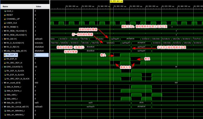
前面初始化的过程略过,只挑选接收过程中的一次接收来讲解:
接收过程其实挺简单的,就是为了增加数据的随机性,对其做了一些处理,包括为了对齐时序对好几个信号多打了拍,看起来信号会比较多。
3、整体仿真
上面说了整体仿真是由例化的两个回环模块构成的:第一个模块发+第二个模块收来判断第一个回环是否正确;第二个模块发+第一个模块收来判断第二个回环是否正确。
(一)第一个回环的仿真结果,信号太多,我们删去一些,只保留部分关键信号:
发送端发送的数据:
接收端接收的数据:
发送与接收一致,回环仿真没问题。
(二)第二个回环的仿真结果:
发送端发送的数据:
接收端接收的数据:
发送与接收一致,回环仿真没问题。
4、总结
- 可以看到Aurora 8B/10B IP核 还是比较容易上手。
- 在官方例程的基础上,把发送和接受模块稍微修改一下,差不多就可以直接拿过来进行简单的使用了。
- 博客主页:wuzhikai.blog.csdn.net
- 本文由 孤独的单刀 原创,首发于CSDN平台
- 您有任何问题,都可以在评论区和我交流!
- 创作不易,您的支持是我持续更新的最大动力!如果本文对您有帮助,还请多多点赞、评论和收藏⭐!


